US4114815A - Apparatus for conninuting solids in liquids - Google Patents
Apparatus for conninuting solids in liquids Download PDFInfo
- Publication number
- US4114815A US4114815A US05/727,808 US72780876A US4114815A US 4114815 A US4114815 A US 4114815A US 72780876 A US72780876 A US 72780876A US 4114815 A US4114815 A US 4114815A
- Authority
- US
- United States
- Prior art keywords
- casing
- cutter
- implement
- slurry
- axis
- Prior art date
- Legal status (The legal status is an assumption and is not a legal conclusion. Google has not performed a legal analysis and makes no representation as to the accuracy of the status listed.)
- Expired - Lifetime
Links
- 239000007787 solid Substances 0.000 title claims abstract description 31
- 239000007788 liquid Substances 0.000 title description 11
- 230000007246 mechanism Effects 0.000 claims abstract description 124
- 210000003608 fece Anatomy 0.000 claims abstract description 92
- 239000010871 livestock manure Substances 0.000 claims abstract description 92
- 239000002002 slurry Substances 0.000 claims abstract description 63
- 239000002689 soil Substances 0.000 claims abstract description 32
- 230000009471 action Effects 0.000 claims abstract description 8
- 239000000470 constituent Substances 0.000 claims description 21
- 230000006835 compression Effects 0.000 claims description 10
- 238000007906 compression Methods 0.000 claims description 10
- 238000010276 construction Methods 0.000 claims description 10
- 210000003746 feather Anatomy 0.000 claims description 10
- 239000002699 waste material Substances 0.000 claims description 9
- 230000007423 decrease Effects 0.000 claims 4
- 238000005086 pumping Methods 0.000 claims 4
- 238000011144 upstream manufacturing Methods 0.000 claims 3
- 238000002347 injection Methods 0.000 abstract description 20
- 239000007924 injection Substances 0.000 abstract description 20
- 238000006073 displacement reaction Methods 0.000 abstract description 3
- 239000000203 mixture Substances 0.000 description 48
- 239000003570 air Substances 0.000 description 12
- 238000004891 communication Methods 0.000 description 7
- 230000008901 benefit Effects 0.000 description 6
- 230000005540 biological transmission Effects 0.000 description 5
- 230000008878 coupling Effects 0.000 description 5
- 238000010168 coupling process Methods 0.000 description 5
- 238000005859 coupling reaction Methods 0.000 description 5
- 239000004575 stone Substances 0.000 description 5
- 241000196324 Embryophyta Species 0.000 description 4
- 238000002203 pretreatment Methods 0.000 description 4
- 230000001105 regulatory effect Effects 0.000 description 3
- 239000011343 solid material Substances 0.000 description 3
- 230000007480 spreading Effects 0.000 description 3
- 241000272814 Anser sp. Species 0.000 description 2
- 230000000712 assembly Effects 0.000 description 2
- 238000000429 assembly Methods 0.000 description 2
- 230000004323 axial length Effects 0.000 description 2
- 230000000694 effects Effects 0.000 description 2
- 230000001788 irregular Effects 0.000 description 2
- 239000000463 material Substances 0.000 description 2
- 230000000717 retained effect Effects 0.000 description 2
- 238000007789 sealing Methods 0.000 description 2
- 244000046052 Phaseolus vulgaris Species 0.000 description 1
- 235000010627 Phaseolus vulgaris Nutrition 0.000 description 1
- 244000061456 Solanum tuberosum Species 0.000 description 1
- 235000002595 Solanum tuberosum Nutrition 0.000 description 1
- 240000008042 Zea mays Species 0.000 description 1
- 235000016383 Zea mays subsp huehuetenangensis Nutrition 0.000 description 1
- 235000002017 Zea mays subsp mays Nutrition 0.000 description 1
- 238000009825 accumulation Methods 0.000 description 1
- 239000012080 ambient air Substances 0.000 description 1
- 230000009286 beneficial effect Effects 0.000 description 1
- 230000015572 biosynthetic process Effects 0.000 description 1
- 230000008859 change Effects 0.000 description 1
- 230000003247 decreasing effect Effects 0.000 description 1
- 230000001419 dependent effect Effects 0.000 description 1
- 230000004720 fertilization Effects 0.000 description 1
- 238000009434 installation Methods 0.000 description 1
- 230000002452 interceptive effect Effects 0.000 description 1
- 238000012423 maintenance Methods 0.000 description 1
- 235000009973 maize Nutrition 0.000 description 1
- 230000004048 modification Effects 0.000 description 1
- 238000012986 modification Methods 0.000 description 1
- 235000012015 potatoes Nutrition 0.000 description 1
- 244000144977 poultry Species 0.000 description 1
- 230000009467 reduction Effects 0.000 description 1
- HBMJWWWQQXIZIP-UHFFFAOYSA-N silicon carbide Chemical compound [Si+]#[C-] HBMJWWWQQXIZIP-UHFFFAOYSA-N 0.000 description 1
- 229910010271 silicon carbide Inorganic materials 0.000 description 1
- 238000009331 sowing Methods 0.000 description 1
- 238000003756 stirring Methods 0.000 description 1
- 239000010902 straw Substances 0.000 description 1
- XLYOFNOQVPJJNP-UHFFFAOYSA-N water Substances O XLYOFNOQVPJJNP-UHFFFAOYSA-N 0.000 description 1
Images


Classifications
-
- A—HUMAN NECESSITIES
- A01—AGRICULTURE; FORESTRY; ANIMAL HUSBANDRY; HUNTING; TRAPPING; FISHING
- A01C—PLANTING; SOWING; FERTILISING
- A01C23/00—Distributing devices specially adapted for liquid manure or other fertilising liquid, including ammonia, e.g. transport tanks or sprinkling wagons
- A01C23/02—Special arrangements for delivering the liquid directly into the soil
- A01C23/021—Sludge injectors, i.e. liquid manure injectors
Definitions
- This invention relates to implements for distributing liquids containing undissolved solids, such as organic manure slurry and other organic manure mixtures, into and/or onto the soil, such implements being of the kind comprising a container for the liquid and means for distributing it under pressure.
- an implement of the kind set forth wherein a cutting mechanism for treating the solid constituents of a liquid to be distributed by the implement is provided, the mechanism being at least partially enclosed by a casing and comprising a cutter arranged to cooperate movably with an apertured counter blade, and wherein the movable cutter extends from a fastening region thereof to a location close to the inner surface of said casing and co-operates throughout at least a greater part of its length between said fastening region and said location with the holes in the counter blade, the means for distributing the liquid under pressure being constructed and arranged to force the liquid through the cutting mechanism by producing a pressure difference between inlet and outlet sides of that mechanism when the implement is in operation.
- FIG. 1 is a side elevation of a self-propelled implement in accordance with the invention constructed and arranged for use in supplying organic manure mixtures into and/or onto the soil,
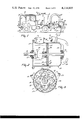
- FIG. 2 is a vertical section, to an enlarged scale, of a cutting mechanism of the implement, said mechanism being located at the right-hand side of FIG. 1,
- FIG. 3 is a section taken on the line III-III in FIG. 2,
- FIG. 4 is a side elevation of an implement that is constructed and arranged for the same purpose as the implement of FIGS. 1 to 3 but which is a towed, rather than self-propelled, implement,
- FIG. 5 is a vertical section, to an enlarged scale, of a cutting mechanism of the implement of FIG. 4 that is to be seen towards the left-hand side of FIG. 4,
- FIG. 6 is a elevation, to the same scale as FIG. 5, but illustrates an alternative construction and arrangement for the cutting mechanism of the implement
- FIG. 7 is a section taken on the line VII-VII in FIG. 6, and
- FIG. 8 is a broken sectional view, to an enlarged scale, illustrating an alternative construction and arrangement for some parts of the cutting mechanism of FIGS. 2 and 3.
- the self-propelled implement that is illustrated therein comprises a container in the form of a cylindrical tank 1, the tank 1 being mounted on the bed of a truck 2 immediately to the rear of a driving cab of that truck.
- Truck 2 has four ground wheels 3 the front two of which are steerable and its intended direction of straight forward travel is indicated in FIG. 1 by an arrow A. It will be appreciated that the precise form of the truck 2 is of no great significance and that it could be varied in many respects as compared with the appearance that is illustrated somewhat diagrammatically in FIG. 1. Purely as an example, truck 2 could have a greater number of the ground wheels 3.
- An air pump 5 is mounted on a bracket 4 carried by the front bumper or fender of truck 2, the pump 5 being arranged to be driven in any convenient manner (that is not illustrated in the drawings) from the adjacent propelling engine of the truck.
- the air pump 5 may be powered from a small independent motor that, in such a case, would also be mounted on the bracket 4.
- a pipe opens into the domed top of the tank 1 and said pipe is connected by a duct 6 and a moisture collector 7 to the pump 5.
- the connection is made by way of a three-way valve 8 which is so arranged that said duct 6 can be placed in communication with either the suction/inlet side of the pump 5 or the compression/outlet side thereof, the third connection of the valve 8 placing that side of the pump 5 which is not coupled to the duct 6 in either case in direct communication with the ambient atmosphere.
- the tank 1 is provided with a flexible suction hose 9 that is arranged for the supply of liquid organic manure mixtures containing undissolved solids to the interior of the tank 1, said hose 9 advantageously having a diameter of substantially 6 inches (151/4 cms).
- the rear of truck 2 with respect to the direction A is provided with a three-point lifting device or hitch 10 to which is connected a rearwardly extending frame 11.
- the frame 11 carries a cutting mechanism 13 that is shown in detail in FIGS. 2 and 3 of the drawings, the cutting mechanism 13 being connected by a hose 12 to the bottom of the tank 1 and to at least two manure injectors 15 by corresponding tubular outlets 25 and flexible hoses 14, said outlets 25 opening into the bottom of the mechanism 13 at locations remote from an upper tubular inlet 24 of said mechanism which is connected to the hose 12.
- the described and illustrated embodiment has two manure injectors 15, it is within the scope of the invention to provide only one manure injector 15 or more than two thereof.
- each injection tine or blade 16 is upwardly and downwardly adjustable in position relative to its mounting on the frame 11 at its upper end, its lower end, that will penetrate more or less deeply into the soil during operation, being inclined forwardly with respect to the direction A from top to bottom by a few degrees.
- each injection tine or blade 16 carries a goose foot-shaped blade 17 having a general plane which is inclined to the horizontal by a few degrees in such a way that the leading edge of the blade with respect to the direction A is at a slightly lower horizontal level than is the rearmost edge thereof.
- Each manure injector 15 is secured to the rear of the corresponding tine of blade 16 with respect to the direction A and is in the form of a tube which conveniently has a diameter of between substantially 4 and subtantially 5 cms.
- each injection tine or blade 16 penetrates downwardly beneath the soil surface by a distance of substantially 15 cms.
- This distance can be set and maintained by upward or downward adjustment of the tines or blades 16 relative to the frame 11, by upward or downward movement of the three-point lifting device or hitch 10 relative to the body of truck 2 and/or by the provision of at least one depth-control ground wheel (not illustrated).
- the cutting mechanism 13 that is shown in detail in FIGS. 2 and 3 of the drawings is driven from the propelling engine of truck 2 by way of a telescopic transmission shaft 18 having universal joints at its opposite ends, the rearmost universal joint of said shaft 18 being coupled to the forwardly projecting end of a substantially horizontally disposed driving shaft 19 of the mechanism 13.
- the mechanism 13 has a casing 20 that is preferably of substantially cylindrical configuration in which case, as illustrated, the driving shaft 19 substantially coincides in position with the longitudinal axis of the casing.
- the rearmost end of the casing 20 comprises a substantially vertically disposed wall at the center of which is arranged a fluid-sealed rotary bearing 21 for the rearmost end of the shaft 19.
- a front wall or cover 22 of the mechanism 13 is secured to a flange of the cylindrically curved wall of the casing by eight bolts and is provided, at its center, with a further fluid-sealed rotary bearing 23for a leading region of the driving shaft 19, said rotary bearing 23 being in substantially horizontal alignment with the rear rotary bearing 21.
- the aforementioned upper tubular inlet 24 that communicates with the hose 12 opens into the cylindrical wall of the mechanism 13 quite close to its front wall or cover 22 and, to match the diameter of the hose 12, advantageously has a diameter of substantially 6 inches (151/4cms.).
- the two tubular outlets 25 open into the rear substantially vertical wall of the casing 20 at locations that are substantially diametrically opposite to the inlet 24 with respect to the geometric center of the housing 20, each tubular outlet 25 advantageously having a diameter of substantially 4 inches (10 cms.).
- the slurry or other organic manure mixture flows into the casing 20 of the mechanism 13 through the tubular inlet 24 in the direction of an arrow B that is shown in FIG. 2 of the drawings and leaves said casing for distribution to the ground through the outlets 25 and the hoses 14 in the direction that is indicated by an arrow C in the same Figure.
- the driving shaft 19 of that mechanism carries a cutter blade 26.
- the cutter blade 26 is releasably fastened to a hub 27 by machine screws and the hub 27 is, in turn, secured against axial and rotational displacement relative to the driving shaft 19 by a releasable set bolt 28.
- the shape of the cutter blade 26 can be seen best in FIG. 3 of the drawings from which it will be evident that said blade is of smoothly curved elliptic shape although its outer edge does not define a true ellipse.
- the shaft 19 passes through the geometric center of the blade 26, the maximum length of that blade between the extremities thereof that are farthest from said shaft 19, and thus quite close to the internal surface of the cylindrically curved portion of the casing 20, having a value of between substantially 35 cms. and substantially 45 cms., a magnitude of substantially 40 cms. being advantageous.
- the minimum width of the blade 26 (measured horizontally in the plane of FIG. 3) has a value of between substantially 15 cms. and substantially 25 cms., a magnitude of substantially 20 cms. being advantageous and being preferred.
- the two ends of the cutter blade 26 that are farthest apart from one another coincide with a straight line that is contained in a longitudinal plane of symmetry of the blade that intersects the axis of the shaft 19.
- the blade 26 that is movable during operation of the implement co-operates with a fixed or counter blade 29 that is in the form of a circular disc having its outer edge region secured to a ring 30 that is fastened to the inner surface of the cylindrically curved portion of the casing 20 in perpendicular relationship with the longitudinal axis of that casing and the substantially coincident longitudinal axis of the driving shaft 19.
- a fixed or counter blade 29 that is in the form of a circular disc having its outer edge region secured to a ring 30 that is fastened to the inner surface of the cylindrically curved portion of the casing 20 in perpendicular relationship with the longitudinal axis of that casing and the substantially coincident longitudinal axis of the driving shaft 19.
- Those portions of the cutter blade 26 which are farthest from the shaft 19 are enclosed between an annular locking element 30A and an outer region of the circular fixed or counter blade 29.
- the element 30A is fastened to the ring 30 with the fixed or counter blade 29 by a plurality, such as four, of
- the fixed or counter blade 29 is formed with a plurality, such as eighteen, of circular holes 31 having positions which can be seen in FIG. 3 of the drawings, but it is emphasized that a greater or lesser number of the holes 31 may be provided, that their sizes and/or positions may be changed and/or that their shapes may be other than circular.
- each hole 31 may be of regular polygonal shape and the plurality of those holes that is provided may be regularly arranged within at least one circumscribing circle. It can be seen in FIG. 2 of the drawings that, with respect to the directions B and C, each hole 31 is frusto-conically divergent through the thickness of the fixed or counter blade 29 from the surface thereof which faces the movable cutter blade 26 to the surface thereof which faces the ring 30.
- each hole 31 should have a diameter of substantially 4 cms. and that diameter should not be greater than substantially 6 cms.
- the holes 31 of the inner and outer rows are radially offset from one another in the surface of the fixed or counter blade 29. It has been found that, in order to ensure that the slurry or other organic manure mixture will flow entirely satisfactorily through the cutting mechanism 13, the total open area of the holes 31 should be substantially 30% greater than the open area of the upper tubular inlet 24.
- a second blade or pre-cutter 32 is disposed before the cutter blade 26 along the driving shaft 19 with respect to the directions B and C.
- the second blade or pre-cutter 32 is located in that chamber of the casing 20 of the mechanism 13 into which slurry or other organic manure mixture is delivered from the tubular inlet 24 in the direction B. It is preferred that, as illustrated, the second blade or pre-cutter 32 should be identical to the cutter blade 26.
- the blade or pre-cutter 32 is secured by countersunk machine screws (not visible) to a sleeve-like hub 33, that hub being secured against axial and angular displacement relative to the shaft 19 by a set bolt 34, the tip of which co-operates with an axially extending groove formed in the surface of the shaft 19.
- the parts 32 and 33 can be retained in different axial positions along the shaft 19 by tightening the set bolt 34 in different settings lengthwise of the groove in the shaft 19.
- the two set bolts 28 and 34 are arranged to co-operate with the shaft 19 in such a way that the cutter blade 26 and second blade or pre-cutter 32 can be spaced apart from one another at different distances and can occupy more or less registering angular settings about the axis of the shaft 19.
- the second blade or pre-cutter 32 should be 90° out of register with the cutter blade 26 about the axis of the shaft 19.
- a line joining the farthest apart extremities of the blade or pre-cutter 32 should be inclined at 90° to a line joining the farthest apart extremities of the cutter blade 26.
- the cylindrically curved wall of the casing 20 should merge into the substantially vertically disposed rear wall thereof by way of rounded corners to ensure a satisfactory flow of the material around those corners and little or no lodgement of solid portions of the material therein.
- the cylindrical casing 20 has a diameter of between substantially 35 cms. and substantially 45 cms., a diameter of substantially 40 cms. being preferred and it will, of course, be realized that this diameter matches the maximum diameter of the cutter blade 26 and the second blade or pre-cutter 32 so that the outer ends of those parts 26 and 32 which are farthest from the shaft 19 closely approach the inner surface of the cylindrically curved wall of the casing 20.
- the fixed or counter blade 29 effectively divides the interior of the casing 20 into a pre-treatment or material-receiving chamber and a post-treatment or delivery chamber. It is important that these two chambers should have definite predetermined volumes and, in the example that is being described, the pre-treatment or material-receiving chamber that is in direct communication with the upper tubular inlet 24 has an axial length of between substantially 15 cms. and substantially 30 cms.
- FIGS. 4 and 5 of the drawings illustrate an alternative form of implement in accordance with the invention which implement is constructed and arranged to be towed by an agricultural tractor 39 or other operating vehicle.
- a chassis 36 of the implement has a triangular towing member 38 at its leading end, with respect to the direction A, said member 38 being adapted to have its apex connected to a tow bar, hitch pin or the like of the tractor 39 or other vehicle.
- the chassis 36 is provided with two pairs of large ground wheels 37 and supports a container in the form of a cylindrical tank 35, the longitudinal axis of which is substantially horizontally disposed.
- An air pump 40 is mounted on the chassis 36 immediately to the rear of the towing member 38 and is arranged to be driven from the power take-off shaft of the agricultural tractor 39 or other operating vehicle by way of an intermediate telescopic transmission shaft 41 that is of a construction which is known per se having universal joints at its opposite ends.
- the air pump 40 may, if preferred, be driven by a small independent motor which would be mounted at the front of the chassis 36.
- a turret at the top and front of the tank 35 with respect to the direction A is connected by a duct 42 to the air pump 40.
- a valve is provided by which said duct 42 can be coupled to either the suction or inlet side of the pump 40 or to the compression or outlet side thereof, that side of the pump which is not coupled to the duct 42 in either case being opened by said valve to the ambient atmosphere.
- An outlet 43 is provided at the rearmost end of the tank 35 and is furnished with a regulating valve 44.
- the operating member of the regulating valve 44 is connected by a lever, rod and pivot system 45 to a handle which projects forwardly at the front of the implement to a location from which it will be accessible to a driver of the tractor 39 or other operating vehicle when the implement is in use. This enables the driver to operate the valve 44 without having to leave his driving seat.
- a substantially horizontally disposed frame 46 extends rearwardly behind the chassis 36 to which chassis said frame 46 is connected by a horizontally disposed pivotal shaft 47 that extends perpendicular to the direction A.
- a double-acting hydraulic piston and cylinder assembly 48 pivotally interconnects a bracket mounted on top of the frame 46 and a lug carried by the tank 35 and is powered from the hydraulic system of the tractor 39 or other vehicle under the control of an operating member that is accessible to the driver of that tractor or other vehicle.
- the hydraulic ducts that are necessary for this purpose are not illustrated in the drawings.
- the frame 46 and the parts which it carries can be turned upwardly and downwardly relative to the chassis 36 about the axis of the pivotal shaft 47.
- the hydraulic piston and cylinder assembly 48 has a stroke length of substantially 80 cms.
- the frame 46 is provided, towards its rear with respect to the direction A, with at least one injection tine or blade 49 that is similar in construction and arrangement to the previously described injection tines or blades 16, each tine or blade 49 having a goose foot-shaped blade 49A at its lowermost end.
- the rear of each injection tine or blade 49 with respect to the direction A has a tubular manure injector 51 secured to it, the upper end thereof being in communication, by way of at least one tube and at least one flexible hose 50, with the delivery side of the regulating valve 44 that is carried by the outlet 43 of the tank 35.
- the flexibility of each hose 50 enables the frame 46 to be turned upwardly or downwardly about the pivotal shaft 47 without interfering with the delivery of slurry or other manure mixture to the or each manure injector 51.
- the outlet 43 of the tank 35 opens from a lower region of a domed manhole or handhole cover 52 that is normally retained in its effective closing position by two clamps 53.
- the cover 52 is of circular shape as viewed in the direction A and, when clamped in its normal closing position, bears surroundingly against a short tubular extension 54 of the tank 35 through the intermediary of a large resilient sealing ring 55 of circular cross-section.
- the short tubular extension 54 of the tank 35 is of circular cross-section and is welded to the rearmost end of said tank very close to the bottom thereof.
- the tubular extension 54 has a diameter of between substantially 40 cms. and substantially 50 cms., a magnitude of substantially 45 cms. being preferred.
- a cutting mechanism 56 is accommodated inside the tubular extension 54 of the tank 35, the rearmost end of a cylindrical casing 57 of said mechanism 56 being welded or otherwise rigidly secured to the inner concave surface of the domed manhole or handhole cover 52.
- the mechanism 56 is, in many respects, similar to the mechanism 13 that has already been described and parts that are substantially identical to parts which have already been discussed in connection with FIGS. 1 to 3 of the drawings are indicated in FIG. 5 of the drawings by the same reference numerals as are employed in FIGS. 2 and 3 of the drawings.
- the cutting mechanism 56 has an axially extending driving shaft 58 which is thus substantially horizontally disposed, the rearmost end of said shaft 58 being rotatably supported by a fluid-sealed bearing 59 at the center of the cover 52 and a leading region thereof being rotatably supported by a further fluid-sealed bearing 60 which is fastenend to two parallel strips 61 of L-shaped cross-section having upper and lower ends which are releasably bolted to inwardly directed upper and lower lugs at the leading edge of the casing 57.
- the shaft 58 passes between the two parallel strips 61 immediately in front of the leading rotary bearing 60.
- the cutter blade 26 is releasably secured by countersunk machine screws (not visible) to a sleeve or ring 62 which surrounds the driving shaft 58 in a manner which enables it to be axially displaceable along that shaft while at the same time it is not significantly angularly displaceable relative thereto. Co-operating splines (not visible) are provided for this purpose.
- the second blade or pre-cutter 32 is also releasably secured by countersunk machine screws (not visible) to a sleeve or ring 63 that is, however, welded or otherwise rigidly secured to the shaft 58.
- a helical compression spring 64 is wound around the shaft 58 so as to bear between the second blade or pre-cutter 32 and the axially displaceable sleeve or ring 62 to which the cutter blade 26 is fastened.
- the spring 64 constantly urges the sleeve or ring 62 and the cutter blade 26 to the left as seen in FIG. 5 of the drawings and thus into intimate self-sharpening engagement with the fixed or counter blade 29.
- That end of the cutting mechanism 56 that faces forwardly with respect to the direction A into the interior of the tank 35 is wholly open around the bearing 60 apart from the provision of the two parallel strips 61 by which that bearing 60 is carried.
- the fixed or counter blade 29 effectively divides the interior of the housing 57 of the mechanism 56 into two separate chambers.
- the outlet 43 of the tank 35 is in direct communication with the post-treatment or delivery chamber of the mechanism 56 that is to the left of the fixed or counter blade 29 as viewed in FIG. 5 of the drawings.
- a rotary shaft 65 that is substantially horizontally disposed extends lengthwise through the tank 35 near the bottom thereof from which it is rotatably supported by at least one sleeve bearing 66.
- the shaft 65 is provided, inside the tank 35, with a plurality of agitator/cutter blades 65A.
- the rearmost end of the shaft 65 is drivingly connected to the leading end of the shaft 58, inside the tank 35, by a fork coupling 67.
- the construction and arrangement of the fork coupling 67 are such that the shaft 58 can be axially disconnected from the shaft 65 without any difficulty when removal of the cutting mechanism 56 from the remainder of the implement is required.
- the pulley 69 is mounted on a rotary output shaft of the air pump 40 and will thus be driven, during operation, from the power take-off shaft of the tractor 39 or other vehicle through the intermediary of the telescopic transmission shaft 41 or from the alternative independent motor that may be provided to drive the air pump 40.
- the driving shaft of the air pump 40 should rotate at a speed of substantially 1500 revolutions per minute and the transmission ratio between the pulleys 69 and 68 is such as to produce a speed of rotation of the shaft 65 of substantially 540 revolutions per minute. However, if desired, the transmission ratio may be changed so that the shaft 65 can be rotated at a speed of up to substantially 1100 revolutions per minute.
- An inlet opening 72 (FIG. 4) is provided for this purpose near the bottom of the tank 35 and near to the front thereof with respect to the direction A, said inlet opening 72 being provided with a manually operable shut-off valve 71 with an actuating lever which projects forwardly to a location where it will be accessible to the driver of the tractor 39 or other operating vehicle without that driver having to leave his seat on the vehicle.
- a manually operable shut-off valve 71 with an actuating lever which projects forwardly to a location where it will be accessible to the driver of the tractor 39 or other operating vehicle without that driver having to leave his seat on the vehicle.
- FIGS. 6 and 7 of the drawings illustrate an alternative to the construction and arrangement that is illustrated in FIGS. 4 and 5 in which a cutting mechanism 73 is partly countersunk into the cylindrically curved side wall of the tank 35 instead of being mounted at the rearmost end thereof as is the mechanism 56.
- the mechanism 73 comprises parts that are identical or substantially identical to parts that have already been described and such parts will not be described in detail again and are indicated in FIGS. 6 and 7 by the same reference numerals as are employed in the preceding Figures.
- the mechanism 73 has a cylindrical casing 74 having a longitudinal axis which is parallel or substantially parallel to that of the cylindrical tank 35, said casing 74 being arranged in the cylindrically curved wall of the tank 35 in such a way that substantially one third of its volume is countersunk into the tank 35 (see FIG. 7).
- an axially disposed driving shaft 75 of the mechanism 73 is located outwardly just beyond said curved wall of the tank 35.
- Angle brackets 76 welded to the external surface of the casing 74 co-operate with the wall of the tank 35 by way of intervening sealing strips, the liquid-sealed co-operation being maintained by a plurality of bolts 77.
- two of the holes 31 in the fixed or counter blade 29 are covered by a sharpening stone 78 releasably mounted on counterblade 29 formed, for example, from silicon carbide.
- the sharpening stone 78 is received in one hole 31 in the outer circular row of those holes and one hole 31 in the inner circular row thereof and ensures that the automatic self-sharpening of the cutter blade 26 by its continuous spring-loaded contact with the fixed or counter blade 29 is continuously and effectively maintained.
- the sharpening stone 78 may, of course, also be provided in the embodiment that is illustrated in FIGS. 2 and 3 of the drawings and in the embodiment that is illustrated in FIG. 5 thereof even though, in the first case, there is no resilient loading of the cutter blade 26 against the fixed or counter blade 29.
- the fixed or counter blade 29 effectively divides the interior of the casing 73 into two chambers, the inlet opening 72 being in direct communication with the pre-treatment or material-receiving chamber while the post-treatment or delivery chamber is located rearwardly of the fixed or counter blade 29 with respect to the direction D (FIG. 7) in which slurry or other organic manure mixture moves through the cutting mechanism 73 during the use of the implement.
- the driving shaft 75 of the mechanism 73 is rotatably journalled at opposite ends of the cylindrical housing 74 in fluid-, or at least liquid-, sealed bearings 80 and 81, the end of said shaft 75 that is closest to the bearing 81 being provided with a pulley 82 to which rotary power is transmitted from a further pulley (not shown) by a V-belt 83.
- the wall of the casing 74 is, of course, formed in the region thereof that is located internally of the tank 35 with a hole 79 of large diameter through which the slurry or other organic manure mixture that has been chopped by the blades of the mechanism 73 passes in the direction D into the tank 35.
- the cutting mechanism 73 that is located at the inlet of the tank 35 could, of course, equally well be provided in the embodiment of FIGS. 1 to 3 of the drawings in which case it would communicate directly with an inlet opening 84 (FIG. 1) of the tank 1.
- the flexible suction hose 9 is, of course, usually connected to the inlet opening 84 when the tank 1 is to be filled.
- a cutting mechanism may be provided in association with both the inlet and the outlet of the tank 1 or 35.
- FIG. 8 of the drawings illustrates, to an enlarged scale, an alternative embodiment of an annular locking member for the rotary cutter blade 26.
- Said annular locking member is in the form of a bent-over portion 20A of the casing 20 and has the shape of a flange which registers with a perpendicularly bent-over flange 20B of a separate, in this embodiment, part of the casing 20.
- An outer edge region of the circular fixed or counter blade 29 is clamped between the bent-over portion 20A and the flange 20B by a plurality of bolts together with an intervening shim plate 20C.
- Shim plates 20C of different thicknesses can be substituted for the illustrated plate 20C or an appropriate number of similar but very thin shim plates can be employed so that the distance between the portion 20A and the flange 20B can be adjusted to compensate for inevitable wear of the rotary cutter blade 26.
- the tank 1 is first filled from a pit or other bulk supply of slurry or other liquid organic manure mixture containing undissolved solids, filling being effected by coupling the hose 9 to the inlet 84 and operating the air pump 5 with the valve 8 in a position in which the duct 6 is coupled to the suction or inlet side of the pump.
- the tank 1 has a moderate capacity of, for example, substantially 2000 liters and the implement of which it forms a part is particularly suitable for use in applying organic manure mixture into and/or onto soil in which plants are growing, or are to be grown, by row culture. Examples of such plants are maize, beans, potatoes and so on.
- the tires of the ground wheels 3 may be relatively narrow in an axial direction without their pressure against the ground surface becoming unacceptably great.
- a tank 1 of greater volumetric capacity than that mentioned above can be used.
- the implement can, of course, be adjusted to distribute the slurry or other organic manure mixture directly onto the ground surface, it is generally preferable to use it in the manner illustrated in the drawings in which all, or most, of the manure is forced into the soil beneath ground level by the air under pressure that is provided from the air pump 5. This way of operating the implement minimizes wastage of the manure and greatly reduces the unpleasant and lingering odor that is produced by direct distribution onto the ground surface.
- the frame 11 that is connected to the three-point lifting device or hitch 10 to the rear of the tank 1 preferably comprises two or more of the injection tines or blades 16 each of which is furnished with a corresponding one of the manure injectors 15.
- the frame 11 to which the injection tines or blades 16 are connected is preferably pivotally mounted with the aid of ball bearings so that the tines or blades 16 and the manure injectors 15 which they carry will be movable not only upwards and downwards to enable the required operating depth to be set but also laterally to some extent. Lateral swingability can be advantageous because the slurry or other manure mixture is then distributed into the soil along more or less zig-zag lines.
- 1 to 3 of the drawings may comprise four of the injection tines or blades 16 and corresponding manure injectors 15 spaced apart from one another in a direction perpendicular to the direction A but, of course, the number of these assemblies and their relative spacing will depend upon the working width of the implement, the spacing between any rows of plants in the land that is to be fertilized and the volume of manure per unit area of land that is to be delivered. Under some working conditions, particularly when the manure injectors 15 are operating at a shallow depth, the use of substantially horizontally disposed covering discs immediately above ground level may be advantageous. Depending upon the nature and condition of the soil that is to be fertilized, the tines or blades 16 may be set to penetrate into the soil to a depth of between substantially 10 and substantially 15 cms. It will be evident that, when more than two of the manure injectors 15 are provided, some branching of the tubular outlets 25 or of the hoses 14 will be necessary but this is not shown in the drawings.
- the three-way valve 8 is moved from the position in which it applies suction to the interior of the tank 1 to the position in which it connects the interior of said tank to the compression/outlet side of the pump 5.
- the inlet opening 84 is, of course, provided with a shut-off valve (not shown) by which it is kept closed when it is not in use.
- a valve 85 (FIG.
- the second blade or pre-cutter 32 rotates in the chamber that has just been mentioned without co-operating with any counterblade or the like but will, of course, cut any large and/or coarse solid constituents of the slurry or other manure mixture into smaller pieces.
- the second blade or pre-cutter 32 is, like the cutter blade 26, of generally elliptical shape and comprises two opposed and arcuately curved convex cutting edges.
- This shape is important and has the practical result that, during operation, large and/or coarse solid lumps of the manure are sliced rather than being chopped. Quite small lumps of the manure are thus produced without damage to the second blade or pre-cutter 32.
- the second blade or pre-cutter 32 is so positioned relative to the tubular inlet 24 that, when the shaft 19 is rotating, lumps of manure entering the mechanism 13 in the direction B meet the cutting edge of the blade 32 that is moving towards them in a substantially opposite direction.
- the collision speed between the blade 32 and the lumps of manure entering in the direction B is thus quite high and this is conductive to rapid and effective slicing of the manure lumps.
- the arrangement of the second blade or pre-cutter 32 in advance of the cutter blade 26 and its co-operating fixed or counter blade 29 with respect to the directions B and C has the advantage that the blade 32 will thoroughly slice up any unusually large and/or coarse lumps of manure before they reach the co-operating parts 26 and 29, thus ensuring that the latter parts will not be subjected to damagingly high loads and that the risk of the mechanism 13 becoming clogged is brought to a very low level.
- the provision of the second blade or pre-cutter 32 increases the volume of slurry or other manure mixture per unit time that can be dealt with effectively by the mechanism 13.
- the second blade or pre-cutter 32 should be provided in all cases but, under most conditions, the irregular and coarse consistency of the solid constituents of manure mixtures makes its provision most desirable.
- an implement in accordance with the invention can inject into the soil mixed manures, that are primarily organic in nature, of almost any composition.
- soil mixed manures that are primarily organic in nature
- mixtures containing coarse poultry manure and feathers, waste fodder, heaped manure with straw, soil and so on can all be dealt with satisfactorily provided only that there is a sufficient liquid content to bring the mixture to an at least semi-liquid condition.
- water can be added to produce the necessary consistency of the mixture when so required.
- a significant advantage of the cutting mechanism 13 is that its tubular outlets 25 may have a small diameter of, conveniently, substantially 4 inches (10 cms.).
- the hoses 14 may thus also be of a matching diameter which is considerably smaller than that of the hoses that are conventionally employed in manure injection work with prior art implements.
- the small diameter has the advantage that the outlets and hoses are less expensive to produce and that the joints between them are light in weight and can be readily manipulated without great effort.
- the cutting mechanism that has been described may advantageously be employed in a spreading implement that has a broad working width and that functions by using a known spreading plate (as described in United Kingdom Pat. No. 813512). Not only are the advantages of the smaller diameter lightweight pipes and hoses and their interconnecting joints obtained but also the advantage that the manure mixture is fed to the soil in a uniformly homogeneous condition so that its beneficial effect upon the soil is improved.
- the cutting mechanism 13 may be employed in a number of implements for distributing manure to the soil which implements also perform other simultaneous operations such as, for example, harrowing, seed sowing, planting and so on.
- the cutting mechanism 13 can be employed in a so-called central conduit system for feeding manure to the soil, the use of the mechanism 13 being particularly advantageous because such systems include very long ducts that are otherwise frequently subject to clogging and blockage.
- the holes 31 may have somewhat larger diameters than are desirable in the case of the implements that have been described but, nevertheless, the holes 31 should not have diameters that are greater than substantially 6 cms.
- the lifetime of each replaceable rotary cutter blade 26 can be effectively doubled if the direction of rotation of the driving shaft 19, 58 or 75 can be reversed since, upon such reversal, the leading and trailing positions of the cutting edges of each cutter blade 26 are interchanged.
- the driving shaft 19 may be provided with a plurality of knives at intervals along its length so that said knives will assist in reducing the size of the lumps or other solid constituents of the manure mixture.
- the speed of rotation of the shaft 19 will normally be of the order of substantially 540 revolutions per minute but, particularly when the shaft 19 is provided with a plurality of knives, the speed of rotation of the shaft may advantageously be raised to substantially 1100 revolutions per minute.
- the speed of rotation of the shaft 19 will be subject to a maximum value whose magnitude will depend upon a number of variable factors.
- An alternative fixed or counter blade 29 may then be provided which has a larger number of holes 31 that are of smaller diameter but, generally speaking, a somewhat increased operating pressure is required under these circumstances. It is noted again that the holes 31 need not be of circular shape. Holes of regular polygonal shape and even holes of irregular shapes arranged inside at least one circumscribing circle will, in most cases, give satisfactory results.
- the cutting edge of the blade 26 advantageously and preferably has a length which is not less than twice the diameter or greatest width of each hole 31 to ensure an optimum cutting action. Whatever the shape of each hole 31, it is greatly preferred that it should be of divergent formation through the thickness of the fixed or counter blade 29 considered in the directions of flow B and C.
- bent-over portion 20A (FIG. 8) of the casing 20 or the annular locking element 30A ensures, throughout the useful lifetime of each cutter blade 26, a satisfactory degree of engagement between that blade and the co-operating fixed or counter blade 29. It is noted that the bent-over portion 20A or the annular locking element 30A can be employed in the cutting mechanism 56 of FIG. 5 or in the cutting mechanism 73 of FIGS.
- the cutting mechanism 13 will only operate in a consistently satisfactory manner if there is an adequate pressure difference between its inlet opening 24 and its tubular outlets 25. It has been found that, if good operating results are to be maintained, this pressure difference should not be less than substantially half an atmosphere and it is noted that, with the described operating pressure of substantially 1 atmosphere and a pressure not much in excess of the ambient atmospheric pressure at the output end of the or each manure injector 15, the required pressure difference of not less than half an atmosphere between the inlet and outlet ends of the cutting mechanism 13 is readily achieved.
- a plurality of manure injectors 15 it can be useful to form the casing 20 of the mechanism 13 with a corresponding plurality of tubular outlets 25 thus making complicated and expensive branched outlet manifolds unnecessary.
- a plurality of tubular outlets 25 is by no means essential since a relatively simple branched outlet manifold to a plurality of the manure injectors 15 will often suffice because the danger of clogging or blockage downstream of the mechanism 13 is very greatly reduced.
- the leading end of the casing 57 is substantially completely open except for the bearing 60 and the strips 61 by which it is supported and, therefore, the raised pressure which is produced in the tank 35 by the pump 40 (preferably substantially 1 atmosphere) causes the mixture to flow towards the outlet 43 as soon as the valve 44 is opened.
- the solid constituents of the manure mixture are first sliced into smaller pieces by the second blade or pre-cutter 32 during after which the mixture moves towards the rotating cutter blade 26 and the co-operating fixed or counter blade 29, those parts reducing the solid constituents of the mixture to a size that will pass through the holes 31 in the fixed or counter blade 29 under the action of the pressure difference between the inlet and outlet sides of the mechanism 56.
- the treated mixture, containing substantially only small solid pieces passes from the post-treatment or delivery chamber of the casing 57 through the outlet 43 in the direction C towards the open valve 44 and the or each manure injector 51.
- each hose 50 and each manure injector 51 may have significantly smaller diameters than are conventional in manure spreading and/or injecting implements that do not comprise a cutting mechanism.
- each injection tine or blade 49 can be moved upwardly or downwardly, as may be required, by turning the frame 46 upwardly or downwardly relative to the chassis 36 about the pivotal shaft 47 using the double-acting piston and cylinder assembly 48 that is controlled from the driving seat of the agricultural tractor or other vehicle that operates the implement.
- the precise number of injection tines or blades 49 that are provided, and the number of associated manure injectors 51, is chosen in accordance with the width of the strip of land that is to be treated, the spacing between a plurality of assemblies 49, 49A and 51 being dictated by the spacing between any rows of plants that are growing, or that are to be grown, upon the land being treated.
- the depth at which the injection of manure takes place should be between substantially 10 cms. and substantially 15 cms. beneath the ground surface depending upon the nature of the soil being treated and its condition at the time of treatment.
- FIGS. 6 and 7 of the drawings When the cutting mechanism 73 of FIGS. 6 and 7 of the drawings is employed in association with the inlet opening 72 of the tank 35, said mechanism performs its function during filling of the tank and the initially untreated manure mixture is caused to flow in the direction B and subsequently, after treatment, in the direction D by the difference between the prevailing atmospheric pressure and the sub-atmospheric pressure that is produced in the tank 35 by the action of the pump 40.
- a cutting mechanism corresponding to the mechanism 73 may be provided in connection with the inlet opening 84 of the embodiment of FIGS.
- valve 85 may, like the other valves that are disposed downstream of at least one of the cutting mechanisms, be of lighter construction and smaller effective diameter than is conventional in ducting for solid-containing organic slurry and other manure mixtures.
- the casing 74 of the mechanism 73 is partly recessed, in a simple manner, into the cylindrically curved wall of the tank 35 very near to the front of that tank with respect to the direction A, said casing 74 being in direct communication with the shut-off valve 71 and its inlet opening 72.
- the mechanism 73 operates in a manner which is very similar to that of the mechanisms 13 and 56.
- the driving shaft 75 of the mechanism 73 is located externally of the tank 35 and is conveniently powered from the pulley 69, or from an adjoining pulley, on the shaft that operates the air pump 40, the drive being transmitted from the pulley 69 or its immediate neighbor to the pulley 82 at the leading end of the shaft 75 by the V-belt 83.
- the speed of operative rotation of the driving shaft 85 is advantageously of the order of 540 revolutions per minute.
- the provision of the sharpening stone 78, including portions extending through adjacent holes 31, in this embodiment ensures that at least the leading cutting edges of the blade 26 are maintained continuously in an optimumly sharp condition during the operation of the implement.
- the spring 64 that is preferably employed in the embodiment of FIGS. 6 and 7 of the drawings urges the rotary blade 26 resiliently against the fixed or counter blade 29 and thus against the sharpening stone 78.
- the arrangement of the cutting mechanism 73 at the inlet, rather than at the outlet, of the tank 35 can be advantageous since it is then not so necessary that said tank should have agitating members such as the blades 65A that have been mentioned and that are illustrated in FIG. 4 of the drawings.
- relatively long flexible hoses and rigid tubes/pipes can be used in association with the tank 35 with a very greatly reduced danger of clogging and blockage.
- the associated valves may also be of smaller diameter and lighter construction than is conventional for dealing with solid-containing manure mixtures.
Landscapes
- Life Sciences & Earth Sciences (AREA)
- Soil Sciences (AREA)
- Engineering & Computer Science (AREA)
- Water Supply & Treatment (AREA)
- Environmental Sciences (AREA)
- Threshing Machine Elements (AREA)
- Fertilizing (AREA)
Applications Claiming Priority (2)
| Application Number | Priority Date | Filing Date | Title |
|---|---|---|---|
| NL7511421 | 1975-09-29 | ||
| NL7511421.A NL163703C (nl) | 1975-09-29 | 1975-09-29 | Inrichting voor het verwerken van vloeibare mest, in het bijzonder mengmest. |
Publications (1)
| Publication Number | Publication Date |
|---|---|
| US4114815A true US4114815A (en) | 1978-09-19 |
Family
ID=19824548
Family Applications (1)
| Application Number | Title | Priority Date | Filing Date |
|---|---|---|---|
| US05/727,808 Expired - Lifetime US4114815A (en) | 1975-09-29 | 1976-09-29 | Apparatus for conninuting solids in liquids |
Country Status (6)
| Country | Link |
|---|---|
| US (1) | US4114815A (fr) |
| CA (1) | CA1049384A (fr) |
| DE (1) | DE2643532A1 (fr) |
| FR (1) | FR2325312A1 (fr) |
| GB (1) | GB1557873A (fr) |
| NL (1) | NL163703C (fr) |
Cited By (16)
| Publication number | Priority date | Publication date | Assignee | Title |
|---|---|---|---|---|
| US4272031A (en) * | 1979-02-21 | 1981-06-09 | Jines Chester G | Vegetation pulverizer |
| US4408724A (en) * | 1981-04-17 | 1983-10-11 | Meyer Charles R | Pulverizer device for handling liquids containing solid and semi-solid materials |
| US4979424A (en) * | 1988-10-21 | 1990-12-25 | Rheinmetall Gmbh | Device for setting a fuse |
| DE9107622U1 (de) * | 1991-06-21 | 1992-10-22 | Hugo Vogelsang Faß- und Maschinenbau GmbH, 4572 Essen | Vorrichtung zum Zerkleinern von Feststoffen in inhomogenen Flüssigkeiten |
| ES2112689A1 (es) * | 1994-03-01 | 1998-04-01 | Guillen Perez Tomas | Maquina distribuidora de estiercol en profundidad. |
| US6802270B1 (en) * | 2002-12-04 | 2004-10-12 | Balzer, Inc. | Trailer incorporating carriage system |
| EP1915895A3 (fr) * | 2006-10-23 | 2009-03-25 | Sörensen, Harry | Distributeur pour la division d'un flux principal de liquide dans plusieurs fluides partiels |
| EP2058046A3 (fr) * | 2007-11-12 | 2009-05-20 | VELO Spa | Machine de filtration pour filtration tangentielle |
| US20100040421A1 (en) * | 2006-11-29 | 2010-02-18 | O'brien & Gere Engineers, Inc. | System for Pneumatically Conveying Particulate Material |
| US20100322756A1 (en) * | 2009-06-23 | 2010-12-23 | Schmidt P E William | Grinder Pump |
| WO2011054059A1 (fr) * | 2009-11-06 | 2011-05-12 | Wayne Frederick Laurence Philips | Procédé et appareil d'application d'une substance à un champ |
| USD653264S1 (en) | 2010-04-05 | 2012-01-31 | Zoeller Pump Company, Llc | Cutter blade |
| DE102010050863A1 (de) * | 2010-11-04 | 2012-05-10 | Mt-Energie Gmbh | Vorrichtung zum Mischen von nicht pumpfähiger Biomasse mit einer Flüssigkeit |
| CN102889248A (zh) * | 2011-06-15 | 2013-01-23 | Ksb股份公司 | 带有集成的切割机的离心泵 |
| EP4413843A1 (fr) * | 2023-02-13 | 2024-08-14 | Alrena B.V. | Plaque de distribution destinée à être utilisée dans un dispositif de distribution et dispositif de distribution pourvu d'une telle plaque de distribution |
| EP4662996A1 (fr) * | 2024-06-11 | 2025-12-17 | Sebastian Zunhammer | Dispositif de transvasement destiné à être monteé sur un véhicule d'épandage agricole ainsi qu'utilisation du dispositif de transvasement |
Families Citing this family (10)
| Publication number | Priority date | Publication date | Assignee | Title |
|---|---|---|---|---|
| NL7514909A (nl) * | 1975-12-22 | 1977-06-24 | Lely Nv C Van Der | Inrichting voor het in of op de grond brengen van vloeibare mest. |
| GB2194421A (en) * | 1986-07-19 | 1988-03-09 | Brian Glassell | Fluid injection unit |
| AT389794B (de) * | 1987-03-04 | 1990-01-25 | Urch Erich | Guellefass |
| EP0383633A1 (fr) * | 1989-02-17 | 1990-08-22 | Aitchison Industries Limited | Injecteur de lisier dans le sol |
| NL8901232A (nl) * | 1989-05-18 | 1990-12-17 | Kamps De Wild B V | Inrichting voor het inbrengen van mest. |
| DE8910777U1 (de) * | 1989-09-09 | 1989-10-26 | Hugo Vogelsang Faß- und Maschinenbau GmbH, 4572 Essen | Vorrichtung zum Verteilen von inhomogenen, feststoffbeladenen Flüssigkeiten, insbesondere Gülle |
| BE1004769A3 (fr) * | 1991-06-25 | 1993-01-26 | Joskin Ets | Repartiteur de lisier et autres liquides. |
| GB9113736D0 (en) * | 1991-06-26 | 1991-08-14 | Greentrac Ltd | Improvements in or relating to injection apparatus for injecting slurry into the ground |
| IES20010924A2 (en) * | 2000-10-24 | 2002-05-29 | John Joseph Mccarthy | A urinal waste treating device |
| BE1032619B1 (fr) | 2024-05-16 | 2025-12-15 | Ets Joskin S A | Repartiteur a ouverture rapide |
Citations (5)
| Publication number | Priority date | Publication date | Assignee | Title |
|---|---|---|---|---|
| US309381A (en) * | 1884-12-16 | Itubeet dollmax | ||
| US431230A (en) * | 1890-07-01 | Charles f | ||
| US1021000A (en) * | 1911-04-12 | 1912-03-26 | William W Mitchell | Meat-chopper. |
| US3323650A (en) * | 1964-12-04 | 1967-06-06 | Jr James A Kilbane | Marine chlorinator |
| US3361369A (en) * | 1964-09-08 | 1968-01-02 | James A Kilbane Jr | Chlorinator and disposal unit for marine water closet |
-
1975
- 1975-09-29 NL NL7511421.A patent/NL163703C/xx not_active IP Right Cessation
-
1976
- 1976-09-23 FR FR7628578A patent/FR2325312A1/fr not_active Withdrawn
- 1976-09-23 GB GB39587/76A patent/GB1557873A/en not_active Expired
- 1976-09-28 DE DE19762643532 patent/DE2643532A1/de not_active Withdrawn
- 1976-09-28 CA CA262,210A patent/CA1049384A/fr not_active Expired
- 1976-09-29 US US05/727,808 patent/US4114815A/en not_active Expired - Lifetime
Patent Citations (5)
| Publication number | Priority date | Publication date | Assignee | Title |
|---|---|---|---|---|
| US309381A (en) * | 1884-12-16 | Itubeet dollmax | ||
| US431230A (en) * | 1890-07-01 | Charles f | ||
| US1021000A (en) * | 1911-04-12 | 1912-03-26 | William W Mitchell | Meat-chopper. |
| US3361369A (en) * | 1964-09-08 | 1968-01-02 | James A Kilbane Jr | Chlorinator and disposal unit for marine water closet |
| US3323650A (en) * | 1964-12-04 | 1967-06-06 | Jr James A Kilbane | Marine chlorinator |
Cited By (20)
| Publication number | Priority date | Publication date | Assignee | Title |
|---|---|---|---|---|
| US4272031A (en) * | 1979-02-21 | 1981-06-09 | Jines Chester G | Vegetation pulverizer |
| US4408724A (en) * | 1981-04-17 | 1983-10-11 | Meyer Charles R | Pulverizer device for handling liquids containing solid and semi-solid materials |
| US4979424A (en) * | 1988-10-21 | 1990-12-25 | Rheinmetall Gmbh | Device for setting a fuse |
| DE9107622U1 (de) * | 1991-06-21 | 1992-10-22 | Hugo Vogelsang Faß- und Maschinenbau GmbH, 4572 Essen | Vorrichtung zum Zerkleinern von Feststoffen in inhomogenen Flüssigkeiten |
| ES2112689A1 (es) * | 1994-03-01 | 1998-04-01 | Guillen Perez Tomas | Maquina distribuidora de estiercol en profundidad. |
| US6802270B1 (en) * | 2002-12-04 | 2004-10-12 | Balzer, Inc. | Trailer incorporating carriage system |
| EP1915895A3 (fr) * | 2006-10-23 | 2009-03-25 | Sörensen, Harry | Distributeur pour la division d'un flux principal de liquide dans plusieurs fluides partiels |
| US20100040421A1 (en) * | 2006-11-29 | 2010-02-18 | O'brien & Gere Engineers, Inc. | System for Pneumatically Conveying Particulate Material |
| EP2058046A3 (fr) * | 2007-11-12 | 2009-05-20 | VELO Spa | Machine de filtration pour filtration tangentielle |
| US8562287B2 (en) | 2009-06-23 | 2013-10-22 | Zoeller Pump Company, Llc | Grinder pump |
| US20100322756A1 (en) * | 2009-06-23 | 2010-12-23 | Schmidt P E William | Grinder Pump |
| WO2011054059A1 (fr) * | 2009-11-06 | 2011-05-12 | Wayne Frederick Laurence Philips | Procédé et appareil d'application d'une substance à un champ |
| US20120298021A1 (en) * | 2009-11-06 | 2012-11-29 | Wayne Frederick Laurence Philips | Method and Apparatus for Applying Matter to a Field |
| US9510500B2 (en) * | 2009-11-06 | 2016-12-06 | Wayne Frederick Laurence Philips | Method and apparatus for applying matter to a field |
| USD653264S1 (en) | 2010-04-05 | 2012-01-31 | Zoeller Pump Company, Llc | Cutter blade |
| DE102010050863A1 (de) * | 2010-11-04 | 2012-05-10 | Mt-Energie Gmbh | Vorrichtung zum Mischen von nicht pumpfähiger Biomasse mit einer Flüssigkeit |
| DE102010050863B4 (de) * | 2010-11-04 | 2016-04-14 | MT-Energie Service GmbH | Vorrichtung zum Mischen von nicht pumpfähiger Biomasse mit einer Flüssigkeit |
| CN102889248A (zh) * | 2011-06-15 | 2013-01-23 | Ksb股份公司 | 带有集成的切割机的离心泵 |
| EP4413843A1 (fr) * | 2023-02-13 | 2024-08-14 | Alrena B.V. | Plaque de distribution destinée à être utilisée dans un dispositif de distribution et dispositif de distribution pourvu d'une telle plaque de distribution |
| EP4662996A1 (fr) * | 2024-06-11 | 2025-12-17 | Sebastian Zunhammer | Dispositif de transvasement destiné à être monteé sur un véhicule d'épandage agricole ainsi qu'utilisation du dispositif de transvasement |
Also Published As
| Publication number | Publication date |
|---|---|
| NL163703C (nl) | 1980-10-15 |
| FR2325312A1 (fr) | 1977-04-22 |
| DE2643532A1 (de) | 1977-04-07 |
| NL7511421A (nl) | 1977-03-31 |
| GB1557873A (en) | 1979-12-12 |
| NL163703B (nl) | 1980-05-16 |
| CA1049384A (fr) | 1979-02-27 |
Similar Documents
| Publication | Publication Date | Title |
|---|---|---|
| US4114815A (en) | Apparatus for conninuting solids in liquids | |
| US3995569A (en) | Two part lawn treating machine | |
| US2878617A (en) | Hydraulic apparatus for seeding, fertilizing, or seeding and fertilizing soil | |
| US4232616A (en) | Device for selectively applying liquid manure onto or into the ground | |
| US5622227A (en) | Multi-functioned farm implement for treating soil | |
| US5361711A (en) | Apparatus for seeding, mulching, and fertilizing soil | |
| US3398707A (en) | Apparatus for working, treating and planting soil | |
| US3316865A (en) | Agricultural implement | |
| CA2780117C (fr) | Procede et appareil d'application d'une substance a un champ | |
| US5272992A (en) | Injection apparatus for injecting slurries/liquids into the ground | |
| US3111917A (en) | Soil tilling and fumigating apparatus | |
| US3685469A (en) | Combination soil conditioner and seeder | |
| US5435493A (en) | Manure distributor with atop discharge pipes and manure spreader incorporating the same | |
| US3237577A (en) | Ammonia applicator | |
| US8584964B2 (en) | Distribution system for liquid manure spreader | |
| US2966128A (en) | Machine for conditioning soil | |
| GB2251166A (en) | Slurry spreaders | |
| CN109673236B (zh) | 一种有机肥环保深施浇灌智能化系统的使用方法 | |
| CN210537423U (zh) | 一种设有施肥装置的水田拖拉机 | |
| US3294407A (en) | Farm machine to load, transport and spread liquid, semi-solid fertilizer | |
| US2756544A (en) | Method and apparatus for dispensing fertilizers to irrigation water | |
| EP0485916B1 (fr) | Appareil pour aérer | |
| US3980236A (en) | Slinger spreader | |
| US3174446A (en) | Power-rotated soil penetrating tool | |
| US2600167A (en) | Fertilizer and seed broadcasting apparatus |