US4123237A - Low pressure drop girth baffle steam separator - Google Patents
Low pressure drop girth baffle steam separator Download PDFInfo
- Publication number
- US4123237A US4123237A US05/781,392 US78139277A US4123237A US 4123237 A US4123237 A US 4123237A US 78139277 A US78139277 A US 78139277A US 4123237 A US4123237 A US 4123237A
- Authority
- US
- United States
- Prior art keywords
- vapor
- liquid
- steam
- flow passage
- water
- Prior art date
- Legal status (The legal status is an assumption and is not a legal conclusion. Google has not performed a legal analysis and makes no representation as to the accuracy of the status listed.)
- Expired - Lifetime
Links
- 239000000203 mixture Substances 0.000 claims abstract description 35
- 239000007788 liquid Substances 0.000 claims description 33
- 238000000926 separation method Methods 0.000 claims description 20
- 239000007787 solid Substances 0.000 claims description 10
- 239000012530 fluid Substances 0.000 claims description 6
- 238000007599 discharging Methods 0.000 claims 2
- XLYOFNOQVPJJNP-UHFFFAOYSA-N water Substances O XLYOFNOQVPJJNP-UHFFFAOYSA-N 0.000 abstract description 91
- 239000000463 material Substances 0.000 description 3
- 238000010276 construction Methods 0.000 description 2
- 238000009434 installation Methods 0.000 description 2
- 230000002411 adverse Effects 0.000 description 1
- 230000000694 effects Effects 0.000 description 1
- 238000004519 manufacturing process Methods 0.000 description 1
- 239000002184 metal Substances 0.000 description 1
- 239000002245 particle Substances 0.000 description 1
- 230000002093 peripheral effect Effects 0.000 description 1
- 239000008400 supply water Substances 0.000 description 1
- 238000003466 welding Methods 0.000 description 1
Images

Classifications
-
- B—PERFORMING OPERATIONS; TRANSPORTING
- B01—PHYSICAL OR CHEMICAL PROCESSES OR APPARATUS IN GENERAL
- B01D—SEPARATION
- B01D45/00—Separating dispersed particles from gases or vapours by gravity, inertia, or centrifugal forces
- B01D45/12—Separating dispersed particles from gases or vapours by gravity, inertia, or centrifugal forces by centrifugal forces
- B01D45/16—Separating dispersed particles from gases or vapours by gravity, inertia, or centrifugal forces by centrifugal forces generated by the winding course of the gas stream, the centrifugal forces being generated solely or partly by mechanical means, e.g. fixed swirl vanes
-
- B—PERFORMING OPERATIONS; TRANSPORTING
- B01—PHYSICAL OR CHEMICAL PROCESSES OR APPARATUS IN GENERAL
- B01D—SEPARATION
- B01D19/00—Degasification of liquids
- B01D19/0042—Degasification of liquids modifying the liquid flow
- B01D19/0052—Degasification of liquids modifying the liquid flow in rotating vessels, vessels containing movable parts or in which centrifugal movement is caused
- B01D19/0057—Degasification of liquids modifying the liquid flow in rotating vessels, vessels containing movable parts or in which centrifugal movement is caused the centrifugal movement being caused by a vortex, e.g. using a cyclone, or by a tangential inlet
-
- B—PERFORMING OPERATIONS; TRANSPORTING
- B01—PHYSICAL OR CHEMICAL PROCESSES OR APPARATUS IN GENERAL
- B01D—SEPARATION
- B01D53/00—Separation of gases or vapours; Recovering vapours of volatile solvents from gases; Chemical or biological purification of waste gases, e.g. engine exhaust gases, smoke, fumes, flue gases, aerosols
- B01D53/26—Drying gases or vapours
-
- F—MECHANICAL ENGINEERING; LIGHTING; HEATING; WEAPONS; BLASTING
- F22—STEAM GENERATION
- F22B—METHODS OF STEAM GENERATION; STEAM BOILERS
- F22B37/00—Component parts or details of steam boilers
- F22B37/02—Component parts or details of steam boilers applicable to more than one kind or type of steam boiler
- F22B37/26—Steam-separating arrangements
- F22B37/32—Steam-separating arrangements using centrifugal force
- F22B37/322—Steam-separating arrangements using centrifugal force specially adapted for boiler drums
Definitions
- This invention relates generally to the separation of fluids from mixtures thereof and, more particularly, to the separation of vapor and liquid from mixtures of the same.
- the separator accordingly, has two essential functions, one of which is the separation of water from steam to provide the downcomers with the steam-free water necessary for proper operation of the circulation system of the vapor generator.
- the other function is the separation of moisture from the steam to provide high-purity steam.
- the pressure drop of the circulating fluid through the separator is an important consideration in that this loss must be minimized to maintain proper circulation in the system.
- Low pressure industrial boilers of present day design are, in general, more highly rated, and efficient separation in the drum, with minimal pressure loss, is essential to furnish steam of the required purity to the point of use and steam-free water to the circulation system.
- the steam-water mixture is generally introduced into a receiving chamber within the steam drum, and through a plurality of inlets into one or more separators.
- the expansion of the mixture through the separator inlets results in a substantial pressure drop, which if too large can adversely affect the circulation system.
- the steam specific volume is high, and a centrifugal separator for this application must have sufficient flow area to minimize pressure loss and still achieve separation.
- an object of the present invention to provide an improved fluid separator for mixtures of a liquid and vapor which produces a relatively low pressure loss in the flow of the mixtures through the separator.
- Another object of the present invention is to provide a liquid-vapor separator which is particularly adapted for use in separating water from a steam-water mixture.
- Another object of the present invention is to provide an improved steam-water separator of simple, efficient and inexpensive design.
- Still another object of the present invention is to provide an improved steam-water separator in which the structural components have simple, semi-cylindrical shapes.
- a further object of the present invention is to provide an improved steam-water separator having relatively large flow passages to reduce pressure loss of the steam-water mixture flowing therethrough.
- Yet a further object of the present invention is to provide an improved steam-water separator particularly adapted for use in a steam drum to remove the water from a steam-water mixture.
- Still a further object of the present invention is to provide a steam-water separator which is compatible with the girth baffle of a steam drum.
- the steam-water separator of the present invention is designed to be an integral extension of the girth baffle of a steam drum and has two, substantially semi-cylindrical elements concentrically separated to provide a curved flow path of approximately 180° for the steam-water mixture.
- the outer, semi-cylindrical water scroll extends 180° and is attached at one edge to a portion of the girth baffle.
- the inner, steam scroll has a semi-cylindrical surface that is solid for 90° of its curvature, with the remaining 90° having a longitudinally-elongated, notched, portion being removed.
- the steam-water mixture introduced into the receiving chamber defined by the girth baffle is conducted between the water and the steam scrolls, and centrifugal force causes the water to separate and flow along the inner surface of the water scroll to be subsequently discharged through a perforated, water splash plate.
- the lighter-density steam flows around the solid, 90° quarter-cylindrical surface of the steam scroll and into the longitudinal flow passage defined by the elongated cut-out on the second 90° portion of the steam scroll, to be discharged from the ends of the separator.
- the semi-cylindrical shape of the scrolls results in a simplier configuration which is cheaper and easier to fabricate, and the relatively large flow passages within the water-steam separator result in a lower pressure drop as the mixture flows through the separator.
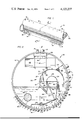
- FIG. 1 is a pictorial perspective of a steam drum incorporating the steam-water separator of the present invention
- FIG. 2 is a cross section of the steam drum along line 2--2 of FIG. 1;
- FIG. 3 is a pictorial view, partially in section, of a plurality of the separators of the present invention, showing more details of the construction thereof;
- FIG. 4 is a partially-sectioned, elevational view along line 4--4 of FIG. 2, showing the steam drum with a plurality of the steam-water separators of the present invention.
- FIG. 5 is a view of the installation along line 5--5 of FIG. 3.
- the reference numeral 10 refers in general to a steam drum, which may be incorporated within a heat transfer apparatus, such as a natural-circulation vapor generating system, in which separators effect the separation of water from a mixture of steam and water.
- the steam drum 10 is generally of an elongated shape with a cylindrical wall 12.
- Banks of steam-generating tubes 14 are connected at their upper ends to a mixture-receiving chamber disposed at the lower portion of the steam drum 10, and a plurality of downcomers 16 extend from the steam drum to return the separated water, mixed with a quantity of feed water, to a boiler (not shown), wherein the water is heated and recycled through the steam drum.
- Dried steam is removed from the steam drum 10 through a plurality of steam conduits 18.
- a plurality of separators 20 are provided in the steam drum 10, with one being visible at the right end of the steam drum as viewed in FIG. 1.
- each separator 20 includes a generally elongated, semi-cylindrical, outer shell 22, commonly called a water scroll, disposed in a concentric, spaced relationship to an inner, elongated, semi-cylindrical shell 24, or a steam scroll, to define a steam-water flow passage therebetween.
- the water scroll 22 has a solid surface which extends for 180° of its curvature, while the steam scroll 24 has a solid, quarter-cylindrical surface extending for approximately 90° of its curvature.
- the remaining 90° of the surface of the steam scroll 24 is removed, as indicated by the cutout 26, with the exception of a short-length, curved portion 28 (FIG. 3) at both ends of the scroll.
- a horizontally-extending, perforated plate 29 joins both lateral edges of the steam scroll 24 to form a longitudinal flow passage for the separated steam.
- FIG. 3 shows a plurality of longitudinally-aligned separators 20, with the water scroll of the separators on the right end of the figure removed for clarity of presentation.
- the cutout 26 of the steam scroll 24 extends circumferentially from substantially the vertical, 90° position of the steam scroll to the very edge thereof, and extends longitudinally for substantially the length of the separator 20, to the curved portions 28 at both ends.
- the steam scroll 24 may be conveniently fabricated from one half of a 12-inch standard pipe of the appropriate length, with a portion of the second quarter-cylindrical surface of the pipe removed to provide the cutout 26 and the end portions 28.
- the perforated plate 29, which has a width equal to the diameter of the pipe from which the steam scroll 24 is fabricated, is then attached to the free edges of the pipe by any suitable means, such as by welding or the like.
- Each separator 20 extends longitudinally a predetermined length, with the ends of the separator being closed by side plates 30 that cover the annulus formed by the water and steam scrolls 22 and 24, respectively.
- a plurality of separators 20 are longitudinally arranged, as shown in FIGS. 3-5, adjacent, longitudinally-disposed separators are spaced apart to provide a passage for the separated steam, as will be described more fully below.
- the water scroll 22 and the steam scroll 24 are connected at their right edges, as viewed in FIG. 2, to internal structure of the steam drum 10 in a manner to be described later, to form an inlet 32 through which the steam-water mixture is introduced into the separator 20.
- the inlet 32 of the separator 20 is formed by a front baffle plate 34 and a rear baffle plate 36, which extends downwardly from the longitudinal edge of the water scroll 22 and the steam scroll 24, respectively.
- the plates 34 and 36 extend for the entire length of the drum 10, are supported at their respective lower ends from the wall 12 of the steam drum 10 by baffle support lugs 37 and 38, and form a portion of the girth baffle structure which is described more fully below.
- the inlet 32 is thus tangentially disposed relative to the water and steam scrolls 22 and 24, respectively.
- An outlet 40 for the separator 20 is defined by the other longitudinal edges of the water scroll 22 and the steam scroll 24. Attached tangentially to the outlet edges of the water and steam scrolls 22 and 24, respectively, are a pair of vertically-extending, water splash hangar plates 42. Attached to the water splash hangar plates 42 are a pair of unequal-length, downwardly-extending, support angles 44, between which are suspended multiple perforated, water splash plates or expanded metal lathe 46, which are disposed at an angle relative to the outlet edges of the water and steam scrolls 22 and 24, respectively, such as at an angle of approximately 45° relative to the support angles 44. One end of a support angle 47 is attached to one of the water splash plate hangers 42, with the other end attached to a baffle support lug 48 to provide the necessary support for the outlet 40 of the separator 20.
- a chamber 50 is provided to receive the steam-water mixture from the steam-generating tubes 14, and is defined on one side by the inner surface of wall 12 of the steam drum 10, through which the tubes extend, and on the other side by a girth baffle, shown in general by the reference numeral 51.
- the girth baffle 51 is formed by the aforesaid front and rear baffle plates 34 and 36, respectively, a vertical, lower baffle plate 52 attached at one edge to the rear baffle plate 36, an inclined lower baffle plate 53, and a deflector plate 54, all of which are appropriately supported and spaced a predetermined distance from the wall by a plurality of baffle support lugs 48.
- An upper baffle plate 55 disposed adjacent to the water scroll 22, cooperates with a pair of radially-extending baffle end plates 56 (one shown in FIG. 2) disposed near the ends of the drum 10 to enclose the chamber 50 and complete the structure of the girth baffle 51.
- the girth baffle 51, and consequently the receiving chamber 50, extend the entire length of the plurality of separators 20, as shown in FIG. 4 and discussed more fully below.
- a longitudinally-extending water feed pipe 58 maintains a relatively constant level of water within the drum to supply water to the boiler (not shown) via the downcomers 16.
- the steam drum 10 is thus divided into a lower, water space and an upper, vapor space, with the separators 20 disposed generally in the vapor space.
- the girth baffle separates the steam-water mixture chamber 50 from the water space, and may be provided with suitable fluid seals.
- a plurality of steam dryers 60 (FIGS. 2 and 4), which extend transversely of the drum and in spaced relationship from the inner peripheral surface of the drum, and extend longitudinally a distance beyond the separators.
- the steam dryers 60 are supported by support members 61, which are attached at their upper ends to the lower surface of a dry box 62.
- the longitudinally-extending dry box 62 attached to the wall 12 of the drum 10 at the upper portion thereof, is in communication with each of the dryers 60 through an inter-connecting nozzle 64. Dried steam is conducted from the dry box 62 through a plurality of conduits 18 extending from the upper surface of the steam drum 10.
- the dryers 60 may be V-shaped in cross section, with each leg of the V having a plurality of W-shaped plates (not shown) inserted therein in a nested but spaced relationship, and may be of the chevron type disclosed in U.S. Pat. No. 2,472,101, issued on June 7, 1949. Remaining entrained water particles carried over with the steam from the separators 20 are separated therefrom as the separated steam flows through the space between the nested plates.
- a plurality of the separators 20 are disposed longitudinally along the length of the steam drum 10, with each separator 20, as defined between successive side plates 30, being spaced from the next, longitudinally-disposed separator to provide a steam passage 68 between adjacent separators.
- the curved, end portions 28 of the steam scrolls 24 extend beyond the side plates 30 of the separators 20 to conduct the steam into the steam passages 68.
- Each steam passage 68 is enclosed on its back side (relative to the orientation of FIG.
- a steam scroll plate 70 which extends circumferentially for approximately 90° of the semi-cylindrical curvature of the separator structure, with the front portion of the steam passage being partially covered by an intermediate closure plate 72 removably attached to the edges of the adjoining separator structure by a plurality of retaining clips 74.
- the forward portion of the intermediate closure plate 72 is directed upwardly with respect to a tangent to the curvature of the water scroll 22, at an angle of about 30°.
- the intermediate enclosure plate 72 may be conveniently fabricated from a single sheet of plate material, with a tongue portion on a leading edge having a narrower width than the rest of the plate and being bent upwardly at the aforesaid 30° orientation.
- the steam passage 68 between adjoining separators 20 is provided with a horizontally-extending, perforated cover plate 76, similar in structure to the perforated plate 29 provided in the steam scroll 24.
- the cover plate 76 extends from the inlet edge of the steam scroll 24 forwardly to the outlet edge of the water scroll 22.
- the remaining horizontal gap at the back portion of the steam passage 68, from the inlet edge of the steam scroll 24 to the inlet edge of the water scroll 22, is covered by a steam seal plate 78.
- the cover plate 76 and the perforated plate 29 may be cut simultaneously to the appropriate shape from the same sheet of material, and be of suitable length to extend longitudinally beneath the plurality of separators 20.
- the perforations in the plates 29 and 76 permit excess water in the separated steam to be drained to the water space in the drum 10.
- the steam-water mixture is introduced into the receiving chamber 50 by the bank of steam-generating tubes 14, which are in fluid communication with the chamber at the upper ends thereof. From the receiving chamber 50, the steam-water mixture is directed tangentially into each of the separators 20 through the inlet 32 between the inner, steam scroll 24 and the outer, water scroll 22 to impinge upon the inner surface of the water scroll. Under the centrifugal action imparted by the combination of the pressure of the mixture and the 180° curvature of the water scroll 22, the more dense water is separated from the mixture and collects on the inner surface of the water scroll. The separated water is discharged through the outlet 40, vertically downwardly through multiple inclined, perforated water splash plates 46, which dissipate the velocity of the water.
- the lower-density steam flows around the outside of the inner, steam scroll 24, and after the steam has passed the covered 90° portion of the steam scroll, it abruptly turns downwardly and flows through the cutout 26 in the steam scroll. From the cutout 26 the steam flows longitudinally in both directions toward the steam passages 68 connecting adjoining separators 20. From each of the steam passages 68, the steam is then discharged upwardly toward the chevron dryers 60, wherein any remaining, entrained water is separated from the steam. The resulting dry steam is collected within the dry box 62 and is removed through the plurality of conduits 18 to a superheater or to the ultimate user of the steam.
Landscapes
- Chemical & Material Sciences (AREA)
- Chemical Kinetics & Catalysis (AREA)
- Engineering & Computer Science (AREA)
- Physics & Mathematics (AREA)
- Thermal Sciences (AREA)
- Mechanical Engineering (AREA)
- General Engineering & Computer Science (AREA)
- Analytical Chemistry (AREA)
- General Chemical & Material Sciences (AREA)
- Oil, Petroleum & Natural Gas (AREA)
- Separating Particles In Gases By Inertia (AREA)
Priority Applications (5)
| Application Number | Priority Date | Filing Date | Title |
|---|---|---|---|
| US05/781,392 US4123237A (en) | 1977-03-25 | 1977-03-25 | Low pressure drop girth baffle steam separator |
| CA293,945A CA1083499A (en) | 1977-03-25 | 1977-12-28 | Low pressure drop girth baffle steam separator |
| MX171924A MX146828A (es) | 1977-03-25 | 1978-01-03 | Mejoras en un separador de vapor y liquido,para separar en vapor y en liquido una mezcla de estos |
| ES466221A ES466221A1 (es) | 1977-03-25 | 1978-01-20 | Separador de vapor y liquido, para separar en vapor y en li-quido una mezcla de estos. |
| GB11783/78A GB1602924A (en) | 1977-03-25 | 1978-03-23 | Vapour and liquid separator |
Applications Claiming Priority (1)
| Application Number | Priority Date | Filing Date | Title |
|---|---|---|---|
| US05/781,392 US4123237A (en) | 1977-03-25 | 1977-03-25 | Low pressure drop girth baffle steam separator |
Publications (1)
| Publication Number | Publication Date |
|---|---|
| US4123237A true US4123237A (en) | 1978-10-31 |
Family
ID=25122579
Family Applications (1)
| Application Number | Title | Priority Date | Filing Date |
|---|---|---|---|
| US05/781,392 Expired - Lifetime US4123237A (en) | 1977-03-25 | 1977-03-25 | Low pressure drop girth baffle steam separator |
Country Status (5)
| Country | Link |
|---|---|
| US (1) | US4123237A (es) |
| CA (1) | CA1083499A (es) |
| ES (1) | ES466221A1 (es) |
| GB (1) | GB1602924A (es) |
| MX (1) | MX146828A (es) |
Cited By (5)
| Publication number | Priority date | Publication date | Assignee | Title |
|---|---|---|---|---|
| US4671214A (en) * | 1985-03-22 | 1987-06-09 | Stein Industrie | Heat exchanger device for drying and superheating steam |
| US5061304A (en) * | 1981-03-27 | 1991-10-29 | Foster Wheeler Energy Corporation | Steam processing apparatus and method |
| US5989302A (en) * | 1996-02-13 | 1999-11-23 | Dltk, Inc. | Steam separator including an interior baffle with openings defining steam ports and a water flow surface |
| CN103007586A (zh) * | 2012-12-25 | 2013-04-03 | 哈尔滨汽轮机厂辅机工程有限公司 | 一种汽水分离器 |
| US11473773B1 (en) * | 2022-04-07 | 2022-10-18 | Superior Boiler Works, Inc. | Steam separator for boiler |
Families Citing this family (1)
| Publication number | Priority date | Publication date | Assignee | Title |
|---|---|---|---|---|
| GB2356242A (en) * | 1999-10-01 | 2001-05-16 | David Oakland | Steam accumulator with centrifugal separators |
Citations (10)
| Publication number | Priority date | Publication date | Assignee | Title |
|---|---|---|---|---|
| US2151863A (en) * | 1937-06-15 | 1939-03-28 | Raymond B Millard | Vapor-liquid separator |
| US2264248A (en) * | 1938-08-23 | 1941-11-25 | Erie City Iron Works | Apparatus for purifying steam from steam generators |
| US2321628A (en) * | 1940-07-06 | 1943-06-15 | Babcock & Wilcox Co | Fluid separator |
| US2675888A (en) * | 1951-10-09 | 1954-04-20 | Foster Wheeler Corp | Vapor and liquid separator |
| US3077714A (en) * | 1961-04-18 | 1963-02-19 | Simpson Herbert Corp | Gas cleaner |
| US3164445A (en) * | 1961-11-07 | 1965-01-05 | American Gas Ass | Grease vapor incinerator |
| US3316692A (en) * | 1965-12-15 | 1967-05-02 | United Aircraft Prod | Liquid storage tank |
| US3450106A (en) * | 1968-02-23 | 1969-06-17 | Foster Wheeler Corp | Tandem separator arrangement |
| US3771290A (en) * | 1971-12-06 | 1973-11-13 | Armstrong Ltd S A | Vortex de-aerator |
| US4019881A (en) * | 1975-06-03 | 1977-04-26 | General Electric Company | Moisture separator for a nuclear steam turbine |
-
1977
- 1977-03-25 US US05/781,392 patent/US4123237A/en not_active Expired - Lifetime
- 1977-12-28 CA CA293,945A patent/CA1083499A/en not_active Expired
-
1978
- 1978-01-03 MX MX171924A patent/MX146828A/es unknown
- 1978-01-20 ES ES466221A patent/ES466221A1/es not_active Expired
- 1978-03-23 GB GB11783/78A patent/GB1602924A/en not_active Expired
Patent Citations (10)
| Publication number | Priority date | Publication date | Assignee | Title |
|---|---|---|---|---|
| US2151863A (en) * | 1937-06-15 | 1939-03-28 | Raymond B Millard | Vapor-liquid separator |
| US2264248A (en) * | 1938-08-23 | 1941-11-25 | Erie City Iron Works | Apparatus for purifying steam from steam generators |
| US2321628A (en) * | 1940-07-06 | 1943-06-15 | Babcock & Wilcox Co | Fluid separator |
| US2675888A (en) * | 1951-10-09 | 1954-04-20 | Foster Wheeler Corp | Vapor and liquid separator |
| US3077714A (en) * | 1961-04-18 | 1963-02-19 | Simpson Herbert Corp | Gas cleaner |
| US3164445A (en) * | 1961-11-07 | 1965-01-05 | American Gas Ass | Grease vapor incinerator |
| US3316692A (en) * | 1965-12-15 | 1967-05-02 | United Aircraft Prod | Liquid storage tank |
| US3450106A (en) * | 1968-02-23 | 1969-06-17 | Foster Wheeler Corp | Tandem separator arrangement |
| US3771290A (en) * | 1971-12-06 | 1973-11-13 | Armstrong Ltd S A | Vortex de-aerator |
| US4019881A (en) * | 1975-06-03 | 1977-04-26 | General Electric Company | Moisture separator for a nuclear steam turbine |
Cited By (6)
| Publication number | Priority date | Publication date | Assignee | Title |
|---|---|---|---|---|
| US5061304A (en) * | 1981-03-27 | 1991-10-29 | Foster Wheeler Energy Corporation | Steam processing apparatus and method |
| US4671214A (en) * | 1985-03-22 | 1987-06-09 | Stein Industrie | Heat exchanger device for drying and superheating steam |
| US5989302A (en) * | 1996-02-13 | 1999-11-23 | Dltk, Inc. | Steam separator including an interior baffle with openings defining steam ports and a water flow surface |
| CN103007586A (zh) * | 2012-12-25 | 2013-04-03 | 哈尔滨汽轮机厂辅机工程有限公司 | 一种汽水分离器 |
| CN103007586B (zh) * | 2012-12-25 | 2014-08-20 | 哈尔滨汽轮机厂辅机工程有限公司 | 一种汽水分离器 |
| US11473773B1 (en) * | 2022-04-07 | 2022-10-18 | Superior Boiler Works, Inc. | Steam separator for boiler |
Also Published As
| Publication number | Publication date |
|---|---|
| MX146828A (es) | 1982-08-25 |
| ES466221A1 (es) | 1978-10-16 |
| GB1602924A (en) | 1981-11-18 |
| CA1083499A (en) | 1980-08-12 |
Similar Documents
| Publication | Publication Date | Title |
|---|---|---|
| US4302227A (en) | Baffled moisture separator | |
| JPS6024405Y2 (ja) | 分離装置を具えた蒸気発生器 | |
| EP0055413A1 (en) | Orificing of steam separators for uniform flow distribution in riser area of steam generators | |
| KR950006505B1 (ko) | 핀이 설치된 액체입자 분리장치 | |
| US4483696A (en) | Steam separating apparatus and separators used therein | |
| US4123237A (en) | Low pressure drop girth baffle steam separator | |
| US2654351A (en) | Fluid separator | |
| US4103647A (en) | Apparatus for drying wet steam and subsequently superheating the dried steam | |
| US3924575A (en) | Fluid heating and separating apparatus | |
| US3195515A (en) | Vapor generator | |
| US2675888A (en) | Vapor and liquid separator | |
| US4565554A (en) | Steam separating apparatus and separators used therein | |
| US4015562A (en) | Moisture separator and reheater | |
| JPH08501141A (ja) | 水・蒸気分離装置 | |
| US2289970A (en) | Steam and water separator | |
| WO1990012983A1 (en) | Method and apparatus for organizing the flow of fluid in a vertical steam generator | |
| CA1169364A (en) | Steam processing apparatus | |
| US3863608A (en) | Steam heating apparatus with moisture separators | |
| US3412713A (en) | Steam generator incorporating floating tube sheet | |
| US3286696A (en) | Vertical steam generator with central downcomber | |
| US2298242A (en) | Steam separator | |
| US2289969A (en) | Fluid heat exchange apparatus | |
| US5061304A (en) | Steam processing apparatus and method | |
| US3566584A (en) | Apparatus for centrifugal and gravitational separation of liouid from gas,particularly water from steam | |
| US3123053A (en) | Horizontal steam generator with a riser manifold |