US4136516A - Gas turbine with secondary cooling means - Google Patents
Gas turbine with secondary cooling means Download PDFInfo
- Publication number
- US4136516A US4136516A US05/803,162 US80316277A US4136516A US 4136516 A US4136516 A US 4136516A US 80316277 A US80316277 A US 80316277A US 4136516 A US4136516 A US 4136516A
- Authority
- US
- United States
- Prior art keywords
- turbine
- blade
- melting point
- point temperature
- hollow
- Prior art date
- Legal status (The legal status is an assumption and is not a legal conclusion. Google has not performed a legal analysis and makes no representation as to the accuracy of the status listed.)
- Expired - Lifetime
Links
- 238000001816 cooling Methods 0.000 title claims abstract description 56
- 239000002826 coolant Substances 0.000 claims abstract description 56
- 238000002844 melting Methods 0.000 claims abstract description 14
- 230000008018 melting Effects 0.000 claims abstract description 14
- 239000012530 fluid Substances 0.000 claims abstract description 12
- 238000004891 communication Methods 0.000 claims abstract description 7
- 239000007789 gas Substances 0.000 claims description 25
- 239000000446 fuel Substances 0.000 claims description 14
- 238000002485 combustion reaction Methods 0.000 claims description 3
- 238000000605 extraction Methods 0.000 claims description 2
- 239000000463 material Substances 0.000 abstract description 5
- 238000005266 casting Methods 0.000 abstract description 2
- 239000003921 oil Substances 0.000 description 37
- 238000000034 method Methods 0.000 description 10
- 230000008901 benefit Effects 0.000 description 6
- 238000013461 design Methods 0.000 description 5
- 230000001172 regenerating effect Effects 0.000 description 5
- 239000010687 lubricating oil Substances 0.000 description 4
- XLYOFNOQVPJJNP-UHFFFAOYSA-N water Substances O XLYOFNOQVPJJNP-UHFFFAOYSA-N 0.000 description 4
- DGAQECJNVWCQMB-PUAWFVPOSA-M Ilexoside XXIX Chemical compound C[C@@H]1CC[C@@]2(CC[C@@]3(C(=CC[C@H]4[C@]3(CC[C@@H]5[C@@]4(CC[C@@H](C5(C)C)OS(=O)(=O)[O-])C)C)[C@@H]2[C@]1(C)O)C)C(=O)O[C@H]6[C@@H]([C@H]([C@@H]([C@H](O6)CO)O)O)O.[Na+] DGAQECJNVWCQMB-PUAWFVPOSA-M 0.000 description 2
- ZLMJMSJWJFRBEC-UHFFFAOYSA-N Potassium Chemical compound [K] ZLMJMSJWJFRBEC-UHFFFAOYSA-N 0.000 description 2
- WYTGDNHDOZPMIW-RCBQFDQVSA-N alstonine Natural products C1=CC2=C3C=CC=CC3=NC2=C2N1C[C@H]1[C@H](C)OC=C(C(=O)OC)[C@H]1C2 WYTGDNHDOZPMIW-RCBQFDQVSA-N 0.000 description 2
- 238000005219 brazing Methods 0.000 description 2
- 239000000567 combustion gas Substances 0.000 description 2
- 238000005516 engineering process Methods 0.000 description 2
- 238000009434 installation Methods 0.000 description 2
- 239000000314 lubricant Substances 0.000 description 2
- 238000005461 lubrication Methods 0.000 description 2
- 238000012423 maintenance Methods 0.000 description 2
- 238000004519 manufacturing process Methods 0.000 description 2
- 229910052700 potassium Inorganic materials 0.000 description 2
- 239000011591 potassium Substances 0.000 description 2
- 230000001141 propulsive effect Effects 0.000 description 2
- 238000005086 pumping Methods 0.000 description 2
- 229910052708 sodium Inorganic materials 0.000 description 2
- 239000011734 sodium Substances 0.000 description 2
- 238000011179 visual inspection Methods 0.000 description 2
- 230000009471 action Effects 0.000 description 1
- 230000006978 adaptation Effects 0.000 description 1
- 238000013459 approach Methods 0.000 description 1
- 238000005452 bending Methods 0.000 description 1
- 230000015572 biosynthetic process Effects 0.000 description 1
- 230000008859 change Effects 0.000 description 1
- 238000010276 construction Methods 0.000 description 1
- 230000008878 coupling Effects 0.000 description 1
- 238000010168 coupling process Methods 0.000 description 1
- 238000005859 coupling reaction Methods 0.000 description 1
- 238000013016 damping Methods 0.000 description 1
- 230000007423 decrease Effects 0.000 description 1
- 230000002950 deficient Effects 0.000 description 1
- 238000011161 development Methods 0.000 description 1
- 230000018109 developmental process Effects 0.000 description 1
- 238000007599 discharging Methods 0.000 description 1
- 230000009977 dual effect Effects 0.000 description 1
- 239000002828 fuel tank Substances 0.000 description 1
- 230000006698 induction Effects 0.000 description 1
- 238000003780 insertion Methods 0.000 description 1
- 230000037431 insertion Effects 0.000 description 1
- 229910001338 liquidmetal Inorganic materials 0.000 description 1
- 238000003754 machining Methods 0.000 description 1
- 230000004048 modification Effects 0.000 description 1
- 238000012986 modification Methods 0.000 description 1
- 230000000704 physical effect Effects 0.000 description 1
- 230000008569 process Effects 0.000 description 1
- 230000008929 regeneration Effects 0.000 description 1
- 238000011069 regeneration method Methods 0.000 description 1
- 230000008439 repair process Effects 0.000 description 1
- 230000000717 retained effect Effects 0.000 description 1
- 125000006850 spacer group Chemical group 0.000 description 1
- 238000005382 thermal cycling Methods 0.000 description 1
- 239000011800 void material Substances 0.000 description 1
Images



Classifications
-
- F—MECHANICAL ENGINEERING; LIGHTING; HEATING; WEAPONS; BLASTING
- F02—COMBUSTION ENGINES; HOT-GAS OR COMBUSTION-PRODUCT ENGINE PLANTS
- F02C—GAS-TURBINE PLANTS; AIR INTAKES FOR JET-PROPULSION PLANTS; CONTROLLING FUEL SUPPLY IN AIR-BREATHING JET-PROPULSION PLANTS
- F02C7/00—Features, components parts, details or accessories, not provided for in, or of interest apart form groups F02C1/00 - F02C6/00; Air intakes for jet-propulsion plants
- F02C7/12—Cooling of plants
- F02C7/16—Cooling of plants characterised by cooling medium
-
- F—MECHANICAL ENGINEERING; LIGHTING; HEATING; WEAPONS; BLASTING
- F01—MACHINES OR ENGINES IN GENERAL; ENGINE PLANTS IN GENERAL; STEAM ENGINES
- F01D—NON-POSITIVE DISPLACEMENT MACHINES OR ENGINES, e.g. STEAM TURBINES
- F01D25/00—Component parts, details, or accessories, not provided for in, or of interest apart from, other groups
- F01D25/08—Cooling; Heating; Heat-insulation
- F01D25/12—Cooling
-
- F—MECHANICAL ENGINEERING; LIGHTING; HEATING; WEAPONS; BLASTING
- F01—MACHINES OR ENGINES IN GENERAL; ENGINE PLANTS IN GENERAL; STEAM ENGINES
- F01D—NON-POSITIVE DISPLACEMENT MACHINES OR ENGINES, e.g. STEAM TURBINES
- F01D5/00—Blades; Blade-carrying members; Heating, heat-insulating, cooling or antivibration means on the blades or the members
- F01D5/12—Blades
- F01D5/14—Form or construction
- F01D5/18—Hollow blades, i.e. blades with cooling or heating channels or cavities; Heating, heat-insulating or cooling means on blades
- F01D5/185—Liquid cooling
-
- Y—GENERAL TAGGING OF NEW TECHNOLOGICAL DEVELOPMENTS; GENERAL TAGGING OF CROSS-SECTIONAL TECHNOLOGIES SPANNING OVER SEVERAL SECTIONS OF THE IPC; TECHNICAL SUBJECTS COVERED BY FORMER USPC CROSS-REFERENCE ART COLLECTIONS [XRACs] AND DIGESTS
- Y02—TECHNOLOGIES OR APPLICATIONS FOR MITIGATION OR ADAPTATION AGAINST CLIMATE CHANGE
- Y02T—CLIMATE CHANGE MITIGATION TECHNOLOGIES RELATED TO TRANSPORTATION
- Y02T50/00—Aeronautics or air transport
- Y02T50/60—Efficient propulsion technologies, e.g. for aircraft
Definitions
- This invention relates to gas turbines and, more particularly, to a concept for efficiently cooling ultrahigh temperature turbine rotor blades.
- gas turbine engine shaft horsepower and specific fuel consumption which is the rate of fuel consumption per unit of power output
- turbine inlet temperatures can be improved by increasing turbine inlet temperatures.
- current turbines are limited in inlet temperature by the physical properties of their materials.
- cooling of high temperature components was limited to transferring heat to lower temperature parts by conduction, and air cooling was limited to passing relatively cool air across the face of the turbine rotor disks.
- thermosiphon a closed-system steam thermosiphon is used to cool the turbine blades, the thermosiphon principle being that by which a coolant is caused to circulate throughout the hollow bores of a turbine blade under the pumping of centrifugal force due to the difference in density between the heated coolant (steam) exiting the blade and the coolant (steam or water) entering it.
- Each blade is provided with its own thermosiphon which is associated with a cooler or heat exchanger which, in turn, is cooled by a second cooling medium such as water or air.
- the above objectives are provided in a gas turbine engine wherein the turbine comprises a rotor disk bearing a plurality of hollow turbine blades, each being individually cooled by steam routed through the hollow interior thereof by the thermosiphon principle.
- compressor discharge or bleed air is also routed to the hollow turbine blades but is precluded from entering therein by a plug filling the bore passage communicating with the hollow blade interior.
- Each blade is also provided with secondary coolant discharge means in the form of passing holes in the blade tip portions. Plugs also fill these holes during the normal operation of the turbine.
- the melting point temperature of the plugs is less than that of the primary structure such that, in the event of failure of the primary coolant system associated with any blades which causes the blade temperature to rise, the tip plugs would melt. As the temperature increases even further, the inlet bore passage plug would melt and the secondary coolant air would rush into the blade interior and out of the tip holes. While such a cooling system would not necessarily be sufficient to hold the blade temperatures to levels which would ensure long life, it would temporarily prolong life until maintenance could be performed.
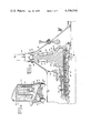
- FIG. 1 is a partial cross-sectional view of an aircraft gas turbojet engine incorporating the subject invention and illustrating schematically the relationship of various engine systems;
- FIG. 2 is a partial cross-sectional view, similar to FIG. 1, depicting the adaptation of the subject invention to an aircraft gas turbofan engine of the dual-spool variety;
- FIG. 3 is an enlarged cross-sectional view of the turbine portion of the engine of FIG. 1 depicting the closed-loop thermosiphon cooling system of the present invention in greater detail;
- FIG. 4 is an enlarged cutaway view of the internal cooling circuitry of a turbine blade of FIG. 3;
- FIG. 5 illustrates an enlarged sector of the turbine as viewed along line 5--5 of FIG. 3, and depicts in more particularity the routing of the coolant passageways along the sides of the turbine disk;
- FIG. 6 is a view, similar to FIG. 3, illustrating an embodiment of the subject invention incorporating a secondary cooling system
- FIG. 7 is a view, similar to FIG. 4, showing the turbine blade internal cooling circuitry in the embodiment of FIG. 6;
- FIG. 8 is an enlarged isometric view of a means for attaching the thermosiphon cooling passageways to the sides of the turbine disk of FIG. 3;
- FIG. 9 is an exploded view of the attaching means of FIG. 8;
- FIG. 10 is a cross-sectional view of the attaching means taken along line 10--10 of FIG. 8;
- FIG. 11 is a plan view, partially in cross section, depicting the attaching means of FIG. 8 in greater detail;
- FIG. 12 is a view, similar to FIG. 8, of an alternative embodiment of the attaching means.
- FIG. 13 is an exploded view of the attaching means of FIG. 12.
- FIG. 1 an aircraft gas turbojet engine depicted generally at 20 and embodying the present invention is diagrammatically shown. While it is recognized that turbojet engines are, by now, well known in the art, a brief description of the operation of the engine will enhance appreciation of the interrelationship of the various components in light of the invention soon to be described.
- the engine may be considered as comprising an axial flow compressor 22 having a rotor 24 bearing a plurality of rotatable blade rows 26 (rotors) and a compressor casing 28 bearing a plurality of stationary blade rows 30 (stators) interposed in alternating relationship with the rotor blade rows 26.
- Turbine rotor 38 comprises a turbine disk 40 bearing a plurality of turbine rotor blades 42, only one of which is shown for clarity, and drives, in turn, the compressor rotor 24 through interconnecting shaft 43 in the usual manner of a gas turbine engine.
- a stationary row of turbine nozzle vanes 44 orient the flow into the rotating turbine blades.
- a propulsive force, to the left in FIG. 1, is thus obtained by the discharge of combustion gases from a representative nozzle 46 defined, in part, by plug 48 and circumscribing shroud 50.
- the engine of FIG. 1 is further provided with a lubrication system including an oil tank or reservoir 52 and a pump 54 which supplies oil under pressure through passage means such as conduit 56 and nozzles 58 to lubricate rear engine bearing 60, and also through conduit 64 and nozzles 66 to lubricate forward engine bearing 68.
- a portion of the oil is also pumped through passage 70 and nozzle 72 to the interior 74 of a rotatable oil duct 76 which is connected to turbine rotor 38 through frustoconical shaft 78 and is rotatable therewith.
- Duct 76 is slightly conical so as to act as a pump to deliver the oil into forward bearing sump 80 from which it is pumped through pump 82 back to the oil tank via conduit 84.
- oil duct 76 The purpose for oil duct 76 will soon become apparent as the description of the invention becomes developed herein. However, it will be appreciated by those skilled in the art that some aircraft gas turbine engines are routinely designed with a center oil duct similar to duct 76 which serves as a conduit to carry and distribute the lubricant to various bearings. An example is that shown in U.S. Pat. No. 3,248,880, which is also assigned to the assignee of the present invention. Therefore, duct 76 or its equivalent may already be present in a gas turbine engine or may be added to the lubrication system, as here, for the purpose of the present invention.
- Turbine blades 42 borne about the perimeter of rotatable turbine disk 40, are provided with an aerodynamically contoured airfoil portion 86 and a base or root portion 88 for attachment to the disc, as by the well-known dovetail method (see FIG. 5).
- the relatively thin exterior walls of the airfoil portion define a substantially hollow interior in the form of serpentine passages 90.
- each blade 42 Connected to the forward and aft ends of the dovetail root 88 of each blade 42 are relatively thin-walled tubes 92 and 94, respectively, which communicate with the hollow interior of the blade through a pair of access openings, inlet 95 and exit 97. Tubes 92 and 94 are connected together by a U-shaped tube 96 to form a closed-loop passageway for each blade. Thus, the number of such closed-loop passageways equals the number of turbine blades in the turbine rotor.
- each closed-loop passageway and more particularly each tube 96, passes.
- This heat exchanger is annular in design, comprising an inner extremity defined by a portion of rotatable oil duct 76 and an outer concentric wall 100, with bulkheads 102 and 104 extending therebetween to define an interior cavity 118.
- These bulkheads are of sufficient thickness to preclude leakage around tubes 96 whether the joints 106 (where the tubes pierce the bulkheads) are brazed or swaged. Note that these joints 106 are exposed to facilitate visual inspection.
- bulkheads 102 and 104 could be of double-wall construction to assure an even better seal around tubes 96.
- Affixed to the outer wall 100 of the heat exchanger are two or more radial flanges 108, 110 which support the exposed portions of tubes 96. Wear collars 112 are fastened to tubes 96 where they are captured by flanges 108, 110 in order to prevent fretting of the tubes.
- oil duct 76 is conical in order to pump oil therethrough by centrifugal pumping action.
- An inwardly extending annular dam 114 diverts at least a portion of the oil through introducing means such as a plurality of holes 116, only one of which is shown for clarity, and into the interior chamber 118 of heat exchanger 98.
- labyrinth means comprising, for example, a series of radial walls 120 which direct the oil over, under and around tubes 96 to absorb heat therefrom in a manner soon to be described.
- An alternative method of providing oil circulation would be to provide an Archimedean screw running through the interior of the heat exchanger for its entire length. In the embodiment of FIG.
- the radial walls 120 provide further support for tubes 96 in the rotating environment.
- Means for discharging oil from the heat exchanger 96 comprising, for example, a second plurality of holes 122, again only one of which being shown for clarity. Oil thus re-enters the interior of oil duct 76 as indicated by the arrows in FIG. 3.
- the oil exit holes 122 are located at a higher radius than the oil inlet holes 116.
- the present invention proposes means for cooling the turbine blades primarily by the thermosiphon principle with steam as a primary cooling medium, although it will become apparent that other coolants such as liquid metals (potassium and sodium) might be equally suitable in certain applications.
- the closed-loop system passageways comprising tubes 92, 94 and 96 and blades 42 may be partially filled with the coolant through any access port (not shown) which is subsequently plugged to conserve the sealed system.
- This means for cooling the blades operates as follows: if water is used as the coolant, it will turn to steam as the turbine rotor is operated at elevated temperatures.
- the heat exchanger be firmly connected tangentially, axially and radially to the turbine disc 40 so as to assure that the turbine rotor disk, shaft 43 and oil duct 76 rotate as a system and to preclude steam tubes 92, 94 and 96 from bending, stretching or twisting unnecessarily.
- means such as interlock 126 are provided between the turbine disk 40 and the heat exchanger 98 to prevent the heat exchanger from rotating with respect to the disk.
- positioning means such as, for example, a lip and rabbet 128 on structural member 130, which extends inwardly from turbine shaft 43, positions the heat exchanger radially and axially with respect to the turbine disk and shaft.
- FIGS. 3, 5 and 8-11 there is depicted a scheme for mechanically attaching tubes 92 and 94 to the outer faces 132, 134, respectively, of turbine disk 40 so as to prevent the heat generated by the steam from affecting the structural integrity of the disk. Note that these tubes pass outside of the disk and not through it so as to further enhance disk structural integrity. Furthermore, the method of mechanical attachment now to be described permits easy assembly and replacement of tubes 92, 94 and blades 40.
- Means for retaining such as a plurality of radially spaced rings 136, are formed integrally with disk 40 and extend generally axially from the faces thereof. These rings serve to support and position tubes 92, 94 axially, radially and tangentially with respect to the disk. As is best shown in FIGS. 8-11 where a portion of one such ring 136 is shown in greater particularity, each ring is provided with a plurality of circumferentially spaced D-shaped slots 138, equal in number to tubes 92 or 94 on the respective disk face and contoured to receive tube wear collars 140 which have been previously placed around the tubes 92, 94 and, possibly, affixed thereto as by brazing. Alternatively, resilient wear tubes could be provided where appropriate.
- the wear collars are provided with upper and lower lips 142, 144, respectively, which sandwich ring 136 and which serve to locate the tubes radially. These collars also protect the tubes from wear due to friction caused by engine vibration and thermal cycling.
- means for locking such as split locking ring 146, is inserted within a retaining groove 148 machined along the bottom edge of ring 136, preferably prior to machining of the slots 138.
- Locking ring 146 completes the capture of collar 140 and, in particular, constrains its axial movement. Radial movement of the locking ring is limited, in turn, by the base of slot 148.
- tubes 94 (and, similarly, tubes 92 on the other disk face) are formed with a series of S-shaped bends between each disk ring 136 and between the radially outermost ring 136 and blade roots 88. These bends provide flexibility to the tubes and prevent the formation of cracks therein due to the centrifugal force field and thermocycling. This flexibility is also desirable from an assembly standpoint due to the tolerance stack-up of the blades, disk, tubes, wear collars and heat exchanger.
- FIGS. 12 and 13 depict an alternative embodiment of the mechanical attachment of tubes 92 and 94 to their respective disk faces.
- a slightly modified collar 150 is split along its longitudinal axis into two halves which may be placed about the tubes prior to insertion into slots 138 of FIGS. 8-11.
- the function and assembly would be the same as that described above.
- the split collar affords more flexibility in assembly in that the tubes may now be bent prior to adding the collar instead of vice ersa.
- rings 136 could be replaced with a plurality of U-shaped retainers 152 located in a ring, the number of which in each row being equal to the number of tubes as hereinbefore.
- D-shaped slots would receive the collars of a type denominated as either 140 or 150 and the retainers would be attached to the disk faces as by bolts 153 (FIG. 13) through the base 154 of each U-shaped retainer.
- the split retainer ring 146 feature of FIGS. 8-11 could be retained as illustrated in FIG. 13 or else individual retaining bands 156 could be installed within the slots of each retainer 154, the ends of the bands being then crimped back 180° and tack-welded together as at 158.
- a resilient liner 155 could be added to collar 150 for damping vibration between the tubing and the collar. While the mechanical attachments of FIGS. 8-13 have been illustrated with respect to their application to a rotating disk, it is clear that these attachments would be equally appropriate for attaching any tubing to any structure, stationary or rotating.
- shafts 43 and 78 are bolted to the disk as at 168 and 170, respectively (FIG. 3). After balancing, the assembly is ready for engine installation. Since the disk tubes and heat exchanger are enclosed by shafts 43 and 78, windage losses from the tubes will not present a problem.
- FIG. 2 illustrates how a somewhat similar steam thermosiphon system could be installed in an aircraft gas turbine engine of the two-spool turbofan variety, as opposed to the single-spool turbojet engine of FIG. 1.
- the hot gases of combustion after driving turbine rotor 38 (which in the terminology of turbofan engines is referred to as the high pressure turbine rotor), pass to and drive a second, low pressure turbine 172 which is typically of the multistage variety and which drives, in turn, a front-mounted fan (not shown) through frustoconical shaft 174 and an inner drive shaft 176.
- This inner drive shaft is hollow, defining to its interior a lubricating oil (coolant) passage 178.
- a slightly modified heat exchanger 180 concentric with shaft 176 is connected to disk 40 and shaft 43 as discussed above, and each closed-loop blade coolant passageway similarly passes through this modified heat exchanger.
- a conical oil duct 182 is attached to the forward end of the heat exchanger as at bolted connection 184.
- Lubricating oil enters passage 178 through oil nozzle 186.
- a plurality of apertures 188 in drive shaft 176 permits the oil to flow into the annular space 190 between drive shaft 176 and the inner wall 192 of heat exchanger 180.
- Dam 194 at least partially spanning passage 178, diverts the oil into apertures 188.
- Windback seals 196, 198 on the inner diameter of the heat exchanger discourage the oil from running anywhere other than through a second plurality of apertures 200 in wall 192 and into the heat exchanger.
- apertures 188, 200, and annular space 190 constitute one example of means for communicating between the coolant passage 178 and heat exchanger 180.
- the oil discharges from the heat exchanger through means communicating between heat exchanger 180 and duct 182 comprising, for example, a series of apertures 202 in the forward bulkhead 204.
- duct 206 Inside of oil duct 182 and spaced between shaft 176 and duct 182 is an intermediate duct 206 carried by duct 182 through spacer webs 208 and defining a coolant annulus 207 in fluid communication with heat exchanger 180. Duct 206 prevents oil from dripping onto drive shaft 176 when the engine rotation stops.
- a system is presented for a gas turbofan engine wherein the heat exchanger, rotating at turbine disk 40 rotational speed is provided with a lubricant from an inner shaft 176 rotating at the low pressure turbine rotational speed.
- the closed-loop thermosiphon is equally applicable, with modification, to gas turbine engines of both the turbojet and turbofan variety.
- FIG. 2 Also depicted schematically in FIG. 2 is an alternative embodiment of the secondary heat exchanger.
- FIG. 1 teaches the use of an oil-fuel heat exchanger to recover at least a portion of the heat removed from the blades and to return it to the engine cycle as heated fuel, thereby functioning as a regenerative engine, it may be satisfactory in some applications to eliminate the regenerative feature, thereby simplifying the system.
- a gas turbofan engine is particularly well suited to using a radiator, shown schematically at 210 and located in the fan bypass duct (not shown), to remove the heat from the oil by placing it in heat exchange relationship with the fan bypass flow stream. In this embodiment, however, the heat would be lost from the cycle.
- FIG. 1 it is preferable to use the regenerative system of FIG. 1 wherever practical.
- compressor rotor 24 a means for extracting a portion of the compressed air from the compressor comprising, for example, a radial inflow compressor stage 212.
- Some of this bleed air circulates inside shafts 43 and 78, obtaining access to the turbine disk through apertures 214 in structural member 130. This bleed air maintains the blade roots and the disk at a reduced temperature level and provides additional cooling for the individual steam thermosiphon circuits.
- FIGS. 6 and 7 wherein one embodiment of a unique secondary cooling system for the closed-loop thermosiphon cooled turbine is diagrammatically shown which utilizes this air bled from compressor rotor 24.
- This secondary cooling scheme is used to provide partial turbine blade cooling in the unlikely event of a steam thermosiphon circuit failure.
- FIG. 7 shows a slightly modified turbine blade 216 which incorporates as its primary method of cooling the closed-circuit, steam thermosiphon principle of FIGS. 3 and 4. Steam enters the hollow, serpentine interior 218 of the blade through tube 92 and exits via tube 94 as described above. However, the blade interior is also in potential fluid communication with a secondary cooling supply through bore 220 in the blade root.
- the secondary coolant supply comprises compressor bleed air which is drawn up through to radially extending bores 222 within slightly modified turbine disk 224. The fabrication and operation of such a bore entry turbine disk is described fully in U.S. Pat. Nos.
- bleed air is pumped radially outwardly through turbine disk bores 222 which communicate with blade bores 220.
- Bores 220 and 222 thus comprise one example of a means for fluidly communicating between the secondary coolant supply and the hollow blade interiors.
- This secondary coolant air is prevented from entering the interior of the turbine blades under normal operating conditions by first filling means such as a melt-out plug 226 which blocks bore passage 220.
- Plug 226 is fabricated of a material having a melting point less than that of the blade primary structure.
- secondary coolant discharge means one form of which being casting holes 228 in the tip portion of the blade, the holes also being provided with second filling means in the form of melt-out plugs 230.
- plugs 230 have a melting point temperature less than that of the primary turbine blade material. Under normal operating conditions, the blame would be cooled by the steam thermosiphon principle. In the event of failure of the primary steam cooling system which causes the temperature of a blade to rise, plugs 230 would melt.
- the secondary cooling air could be drawn into the blades through a conventional rim entry system wherein the blade inlet passages are located proximate the turbine disk outer rim.
- a conventional coolant system is typified by U.S. Pat. No. 3,891,348 which is assigned to the assignee of the present invention and the subject matter of which is also incorporated herein by reference.
- Yet another embodiment would be to cast a small secondary air-cooling circuit in the blade along with, but fluidly divorced from, the primary steam circuit.
- the dual cooling approach offers the advantage of increased reliability.
- the turbine blade cooling system described herein offers many advantages over prior art systems.
- the steam-oil heat exchanger has been designed and placed in the engine in such a manner that it does not change the configuration or design of nearby hardware since it has been placed in an area which was otherwise vacant. Thus, it does not increase the engine length or diameter. Because it is located at the lowest possible diameter, the design is compact, lightweight, void of high stresses and has virtually no balance problems since all the blade coolant circuits have equal amounts of coolant.
- Other liquid-cooled turbines have suffered vibration problems because each blade or circuit was fed from a common source such as from a distributor or manifold.
- the present invention employs conventional turbine disks, and a common, safe, on-board, secondary coolant (oil) is used.
- the more volatile fuel coolants are divorced from the turbine rotor structure.
- the system employs conventional manufacturing techniques with relatively low cost, longlife turbine blades. Minimum reliance is placed on precious compressor bleed air. However, means are provided to use this air in a secondary capacity as a back-up coolant system. The low diameter design is ideal for bringing this secondary cooling air in and out of the blades. Also, the system can be the basis for a regenerative engine with resultant decreases in engine specific fuel consumption. Finally, each blade is provided with an individual cooling circuit such that failure of one circuit would not necessarily jeopardize the entire turbine.
Landscapes
- Engineering & Computer Science (AREA)
- Mechanical Engineering (AREA)
- General Engineering & Computer Science (AREA)
- Chemical & Material Sciences (AREA)
- Combustion & Propulsion (AREA)
- Turbine Rotor Nozzle Sealing (AREA)
- Control Of Turbines (AREA)
Priority Applications (6)
| Application Number | Priority Date | Filing Date | Title |
|---|---|---|---|
| US05/803,162 US4136516A (en) | 1977-06-03 | 1977-06-03 | Gas turbine with secondary cooling means |
| GB14368/78A GB1600109A (en) | 1977-06-03 | 1978-04-12 | Gas turbine with secondary cooling means |
| DE19782823496 DE2823496A1 (de) | 1977-06-03 | 1978-05-30 | Gasturbine mit sekundaeren kuehlungsmitteln |
| JP6497378A JPS5416016A (en) | 1977-06-03 | 1978-06-01 | Gas turbine with secondary cooler |
| IT24101/78A IT1096412B (it) | 1977-06-03 | 1978-06-01 | Turbina a gas con sistema secondario di raffreddamento |
| FR7816596A FR2393152A1 (fr) | 1977-06-03 | 1978-06-02 | Turbine a circuit de refroidissement de secours |
Applications Claiming Priority (1)
| Application Number | Priority Date | Filing Date | Title |
|---|---|---|---|
| US05/803,162 US4136516A (en) | 1977-06-03 | 1977-06-03 | Gas turbine with secondary cooling means |
Publications (1)
| Publication Number | Publication Date |
|---|---|
| US4136516A true US4136516A (en) | 1979-01-30 |
Family
ID=25185739
Family Applications (1)
| Application Number | Title | Priority Date | Filing Date |
|---|---|---|---|
| US05/803,162 Expired - Lifetime US4136516A (en) | 1977-06-03 | 1977-06-03 | Gas turbine with secondary cooling means |
Country Status (6)
| Country | Link |
|---|---|
| US (1) | US4136516A (it) |
| JP (1) | JPS5416016A (it) |
| DE (1) | DE2823496A1 (it) |
| FR (1) | FR2393152A1 (it) |
| GB (1) | GB1600109A (it) |
| IT (1) | IT1096412B (it) |
Cited By (54)
| Publication number | Priority date | Publication date | Assignee | Title |
|---|---|---|---|---|
| US4456428A (en) * | 1979-10-26 | 1984-06-26 | S.N.E.C.M.A. | Apparatus for cooling turbine blades |
| US4462754A (en) * | 1981-06-30 | 1984-07-31 | Rolls Royce Limited | Turbine blade for gas turbine engine |
| US4645415A (en) * | 1983-12-23 | 1987-02-24 | United Technologies Corporation | Air cooler for providing buffer air to a bearing compartment |
| US4835958A (en) * | 1978-10-26 | 1989-06-06 | Rice Ivan G | Process for directing a combustion gas stream onto rotatable blades of a gas turbine |
| US4940388A (en) * | 1988-12-07 | 1990-07-10 | Rolls-Royce Plc | Cooling of turbine blades |
| US5022817A (en) * | 1989-09-12 | 1991-06-11 | Allied-Signal Inc. | Thermostatic control of turbine cooling air |
| US5178514A (en) * | 1983-05-26 | 1993-01-12 | Rolls-Royce Plc | Cooling of gas turbine shroud rings |
| US5240069A (en) * | 1992-07-06 | 1993-08-31 | The United States Of America As Represented By The Secretary Of The Air Force | Integral cooling system for a jet engine integral starter/generator and the like |
| US5317877A (en) * | 1992-08-03 | 1994-06-07 | General Electric Company | Intercooled turbine blade cooling air feed system |
| US5536143A (en) * | 1995-03-31 | 1996-07-16 | General Electric Co. | Closed circuit steam cooled bucket |
| US5813835A (en) * | 1991-08-19 | 1998-09-29 | The United States Of America As Represented By The Secretary Of The Air Force | Air-cooled turbine blade |
| US5971707A (en) * | 1997-07-07 | 1999-10-26 | Mitsubishi Heavy Industries, Ltd. | Gas turbine moving blade steam cooling system |
| US5984637A (en) * | 1997-02-21 | 1999-11-16 | Mitsubishi Heavy Industries, Ltd. | Cooling medium path structure for gas turbine blade |
| US6000909A (en) * | 1997-02-21 | 1999-12-14 | Mitsubishi Heavy Industries, Ltd. | Cooling medium path in gas turbine moving blade |
| US6036440A (en) * | 1997-04-01 | 2000-03-14 | Mitsubishi Heavy Industries, Ltd. | Gas turbine cooled moving blade |
| WO2000019065A1 (de) * | 1998-09-30 | 2000-04-06 | Siemens Aktiengesellschaft | Gasturbinenlaufschaufel und verfahren zur herstellung einer gasturbinenlaufschaufel |
| EP0930419A4 (en) * | 1997-06-06 | 2001-03-07 | Mitsubishi Heavy Ind Ltd | GAS TURBINE DAWN |
| US6565311B2 (en) * | 2000-11-21 | 2003-05-20 | Mitsubishi Heavy Industries, Ltd. | Gas turbine steam passage seal structure between blade ring and stationary blade |
| US20040151580A1 (en) * | 2003-02-03 | 2004-08-05 | Helder Earl Claude | Methods and apparatus for coupling a component to a turbine engine blade |
| US20040226682A1 (en) * | 2002-10-30 | 2004-11-18 | Jan Ehrhard | Emergency cooling system for a thermally loaded component |
| US20050238488A1 (en) * | 2004-04-27 | 2005-10-27 | General Electric Company | Turbulator on the underside of a turbine blade tip turn and related method |
| WO2005103451A1 (de) * | 2004-04-22 | 2005-11-03 | Mtu Aero Engines Gmbh | Verfahren zum verschliessen einer kernaustrittsöffnung einer turbinenschaufel und turbinenschaufel |
| US20050271512A1 (en) * | 2003-11-28 | 2005-12-08 | Rainer Mielke | Method and apparatus for coating or heat treatment of blisks for aircraft gas turbines |
| US20070036942A1 (en) * | 2005-08-11 | 2007-02-15 | Rolls-Royce Plc | Cooling method and apparatus |
| US20070039305A1 (en) * | 2005-08-19 | 2007-02-22 | General Electric Company | Lubricating Oil Heat Recovery System for Turbine Engines |
| US20070139193A1 (en) * | 2005-12-16 | 2007-06-21 | Mehmet Arik | Wireless monitoring system |
| US20070261826A1 (en) * | 2004-09-16 | 2007-11-15 | Holmen Hans K | Method and a System for Energy Recovery and/or Cooling |
| US20080050242A1 (en) * | 2006-08-24 | 2008-02-28 | Siemens Power Generation, Inc. | Turbine airfoil cooling system with perimeter cooling and rim cavity purge channels |
| EP2216509A1 (de) * | 2009-02-04 | 2010-08-11 | Siemens Aktiengesellschaft | Turbinenbauteil mit leicht entfernbarer Schutzschicht, Satz von Turbinenbauteilen, eine Turbine und ein Verfahren zum Schützen eines Turbinenbauteils |
| US20100221099A1 (en) * | 2009-02-27 | 2010-09-02 | General Electric Company | Apparatus, methods, and/or systems relating to the delivery of a fluid through a passageway |
| US20100247292A1 (en) * | 2009-03-30 | 2010-09-30 | General Electric Company | System and Method of Cooling Turbine Airfoils with Sequestered Carbon Dioxide |
| US20100326048A1 (en) * | 2008-12-29 | 2010-12-30 | Lozier Thomas S | Gas turbine engine duct having a coupled fluid volume |
| US20100329887A1 (en) * | 2009-06-26 | 2010-12-30 | Andy Eifert | Coolable gas turbine engine component |
| US20110076155A1 (en) * | 2008-03-28 | 2011-03-31 | Alstom Technology Ltd. | Guide blade for a gas turbine |
| US20110189015A1 (en) * | 2010-02-02 | 2011-08-04 | Andrew Shepherd | turbine engine component for adaptive cooling |
| US8007242B1 (en) * | 2009-03-16 | 2011-08-30 | Florida Turbine Technologies, Inc. | High temperature turbine rotor blade |
| US8052391B1 (en) * | 2009-03-25 | 2011-11-08 | Florida Turbine Technologies, Inc. | High temperature turbine rotor blade |
| US8070450B1 (en) * | 2009-04-20 | 2011-12-06 | Florida Turbine Technologies, Inc. | High temperature turbine rotor blade |
| US20120094243A1 (en) * | 2009-04-10 | 2012-04-19 | Elena Sanz Garcia | Rotary furnace for heat treatment of solids |
| US20120230825A1 (en) * | 2009-11-13 | 2012-09-13 | Mtu Aero Engines Gmbh | Gas turbine blade for a turbomachine |
| US8628298B1 (en) * | 2011-07-22 | 2014-01-14 | Florida Turbine Technologies, Inc. | Turbine rotor blade with serpentine cooling |
| US9353687B1 (en) * | 2012-10-18 | 2016-05-31 | Florida Turbine Technologies, Inc. | Gas turbine engine with liquid metal cooling |
| US9382801B2 (en) | 2014-02-26 | 2016-07-05 | General Electric Company | Method for removing a rotor bucket from a turbomachine rotor wheel |
| US9488104B2 (en) | 2013-03-15 | 2016-11-08 | Rolls-Royce Corporation | Gas turbine engine lubrication system |
| US9976485B2 (en) | 2012-02-27 | 2018-05-22 | United Technologies Corporation | Gas turbine engine buffer cooling system |
| US20180216473A1 (en) * | 2017-01-31 | 2018-08-02 | United Technologies Corporation | Hybrid airfoil cooling |
| US20180347372A1 (en) * | 2017-05-31 | 2018-12-06 | General Electric Company | Adaptively opening backup cooling pathway |
| US20190003315A1 (en) * | 2017-02-03 | 2019-01-03 | General Electric Company | Fluid cooling systems for a gas turbine engine |
| US10443620B2 (en) | 2018-01-02 | 2019-10-15 | General Electric Company | Heat dissipation system for electric aircraft engine |
| US10815887B2 (en) | 2013-03-15 | 2020-10-27 | Rolls-Royce Corporation | Gas turbine engine lubrication system |
| US11125160B2 (en) | 2015-12-28 | 2021-09-21 | General Electric Company | Method and system for combination heat exchanger |
| US20230003131A1 (en) * | 2021-07-02 | 2023-01-05 | Hamilton Sundstrand Corporation | Radial turbine rotor with complex cooling channels and method of making same |
| EP4276280A4 (en) * | 2022-03-29 | 2023-12-06 | Beihang University | Aero-engine turbine assembly |
| US20240102417A1 (en) * | 2022-09-23 | 2024-03-28 | Raytheon Technologies Corporation | Air recuperated engine with air reinjection |
Families Citing this family (7)
| Publication number | Priority date | Publication date | Assignee | Title |
|---|---|---|---|---|
| US5279111A (en) * | 1992-08-27 | 1994-01-18 | Inco Limited | Gas turbine cooling |
| DE4336143C2 (de) * | 1993-10-22 | 1995-11-16 | Erich Wuerzinger | Kühlverfahren für Turbomaschinen |
| WO1996034191A1 (en) * | 1995-04-24 | 1996-10-31 | Westinghouse Electric Corporation | Improved cooling system for combustion turbine |
| GB2354043A (en) * | 1999-08-24 | 2001-03-14 | Fred Starr | Cooling radial flow turbine |
| DE60026236T2 (de) * | 1999-08-24 | 2006-11-23 | General Electric Co. | Dampfkühlungssystem für eine Gasturbine |
| US9249669B2 (en) * | 2012-04-05 | 2016-02-02 | General Electric Company | CMC blade with pressurized internal cavity for erosion control |
| FR3092134B1 (fr) * | 2019-01-30 | 2021-02-12 | Safran Aircraft Engines | turbine avec dispositif d’équilibrage amélioré |
Citations (6)
| Publication number | Priority date | Publication date | Assignee | Title |
|---|---|---|---|---|
| US2565594A (en) * | 1946-09-20 | 1951-08-28 | Power Jets Res & Dev Ltd | Turbine and the like |
| US2782000A (en) * | 1951-05-28 | 1957-02-19 | Simmering Graz Pauker Ag | Gas-turbine |
| US3164367A (en) * | 1962-11-21 | 1965-01-05 | Gen Electric | Gas turbine blade |
| US3623825A (en) * | 1969-11-13 | 1971-11-30 | Avco Corp | Liquid-metal-filled rotor blade |
| US3756020A (en) * | 1972-06-26 | 1973-09-04 | Curtiss Wright Corp | Gas turbine engine and cooling system therefor |
| US3990837A (en) * | 1974-12-07 | 1976-11-09 | Rolls-Royce (1971) Limited | Combustion equipment for gas turbine engines |
-
1977
- 1977-06-03 US US05/803,162 patent/US4136516A/en not_active Expired - Lifetime
-
1978
- 1978-04-12 GB GB14368/78A patent/GB1600109A/en not_active Expired
- 1978-05-30 DE DE19782823496 patent/DE2823496A1/de not_active Withdrawn
- 1978-06-01 JP JP6497378A patent/JPS5416016A/ja active Pending
- 1978-06-01 IT IT24101/78A patent/IT1096412B/it active
- 1978-06-02 FR FR7816596A patent/FR2393152A1/fr active Granted
Patent Citations (6)
| Publication number | Priority date | Publication date | Assignee | Title |
|---|---|---|---|---|
| US2565594A (en) * | 1946-09-20 | 1951-08-28 | Power Jets Res & Dev Ltd | Turbine and the like |
| US2782000A (en) * | 1951-05-28 | 1957-02-19 | Simmering Graz Pauker Ag | Gas-turbine |
| US3164367A (en) * | 1962-11-21 | 1965-01-05 | Gen Electric | Gas turbine blade |
| US3623825A (en) * | 1969-11-13 | 1971-11-30 | Avco Corp | Liquid-metal-filled rotor blade |
| US3756020A (en) * | 1972-06-26 | 1973-09-04 | Curtiss Wright Corp | Gas turbine engine and cooling system therefor |
| US3990837A (en) * | 1974-12-07 | 1976-11-09 | Rolls-Royce (1971) Limited | Combustion equipment for gas turbine engines |
Non-Patent Citations (1)
| Title |
|---|
| Japikse et al., "Mixed Convection Thermosyphon and Gas Turbine Blade Cooling", ASME Paper No. 73 WA/HT26. * |
Cited By (89)
| Publication number | Priority date | Publication date | Assignee | Title |
|---|---|---|---|---|
| US4835958A (en) * | 1978-10-26 | 1989-06-06 | Rice Ivan G | Process for directing a combustion gas stream onto rotatable blades of a gas turbine |
| US4456428A (en) * | 1979-10-26 | 1984-06-26 | S.N.E.C.M.A. | Apparatus for cooling turbine blades |
| US4462754A (en) * | 1981-06-30 | 1984-07-31 | Rolls Royce Limited | Turbine blade for gas turbine engine |
| US5178514A (en) * | 1983-05-26 | 1993-01-12 | Rolls-Royce Plc | Cooling of gas turbine shroud rings |
| US4645415A (en) * | 1983-12-23 | 1987-02-24 | United Technologies Corporation | Air cooler for providing buffer air to a bearing compartment |
| US4940388A (en) * | 1988-12-07 | 1990-07-10 | Rolls-Royce Plc | Cooling of turbine blades |
| GB2228540A (en) * | 1988-12-07 | 1990-08-29 | Rolls Royce Plc | Cooling of turbine blades |
| GB2228540B (en) * | 1988-12-07 | 1993-03-31 | Rolls Royce Plc | Cooling of turbine blades |
| US5022817A (en) * | 1989-09-12 | 1991-06-11 | Allied-Signal Inc. | Thermostatic control of turbine cooling air |
| US5813835A (en) * | 1991-08-19 | 1998-09-29 | The United States Of America As Represented By The Secretary Of The Air Force | Air-cooled turbine blade |
| US5240069A (en) * | 1992-07-06 | 1993-08-31 | The United States Of America As Represented By The Secretary Of The Air Force | Integral cooling system for a jet engine integral starter/generator and the like |
| US5317877A (en) * | 1992-08-03 | 1994-06-07 | General Electric Company | Intercooled turbine blade cooling air feed system |
| US5536143A (en) * | 1995-03-31 | 1996-07-16 | General Electric Co. | Closed circuit steam cooled bucket |
| EP0860587A3 (en) * | 1997-02-21 | 2001-03-21 | Mitsubishi Heavy Industries, Ltd. | Connector for the transfer of a cooling fluid from a rotor disc to a turbomachine blade |
| US5984637A (en) * | 1997-02-21 | 1999-11-16 | Mitsubishi Heavy Industries, Ltd. | Cooling medium path structure for gas turbine blade |
| US6000909A (en) * | 1997-02-21 | 1999-12-14 | Mitsubishi Heavy Industries, Ltd. | Cooling medium path in gas turbine moving blade |
| US6036440A (en) * | 1997-04-01 | 2000-03-14 | Mitsubishi Heavy Industries, Ltd. | Gas turbine cooled moving blade |
| EP0930419A4 (en) * | 1997-06-06 | 2001-03-07 | Mitsubishi Heavy Ind Ltd | GAS TURBINE DAWN |
| US6257830B1 (en) * | 1997-06-06 | 2001-07-10 | Mitsubishi Heavy Industries, Ltd. | Gas turbine blade |
| US5971707A (en) * | 1997-07-07 | 1999-10-26 | Mitsubishi Heavy Industries, Ltd. | Gas turbine moving blade steam cooling system |
| WO2000019065A1 (de) * | 1998-09-30 | 2000-04-06 | Siemens Aktiengesellschaft | Gasturbinenlaufschaufel und verfahren zur herstellung einer gasturbinenlaufschaufel |
| US6565311B2 (en) * | 2000-11-21 | 2003-05-20 | Mitsubishi Heavy Industries, Ltd. | Gas turbine steam passage seal structure between blade ring and stationary blade |
| US7077622B2 (en) * | 2002-10-30 | 2006-07-18 | Alstom Technology Ltd. | Emergency cooling system for a thermally loaded component |
| US20040226682A1 (en) * | 2002-10-30 | 2004-11-18 | Jan Ehrhard | Emergency cooling system for a thermally loaded component |
| US20040151580A1 (en) * | 2003-02-03 | 2004-08-05 | Helder Earl Claude | Methods and apparatus for coupling a component to a turbine engine blade |
| US6964557B2 (en) * | 2003-02-03 | 2005-11-15 | General Electric Company | Methods and apparatus for coupling a component to a turbine engine blade |
| US20050271512A1 (en) * | 2003-11-28 | 2005-12-08 | Rainer Mielke | Method and apparatus for coating or heat treatment of blisks for aircraft gas turbines |
| US20100034974A1 (en) * | 2003-11-28 | 2010-02-11 | Rainer Mielke | Method and apparatus for coating or heat treatment of blisks for aircraft gas turbines |
| US8029865B2 (en) * | 2003-11-28 | 2011-10-04 | Rolls-Royce Deutschland Ltd & Co Kg | Method for coating or heat treatment of blisks for aircraft gas turbines |
| US7413610B2 (en) * | 2003-11-28 | 2008-08-19 | Rolls-Royce Deutschland Ltd & Co Kg | Method and apparatus for coating or heat treatment of blisks for aircraft gas turbines |
| WO2005103451A1 (de) * | 2004-04-22 | 2005-11-03 | Mtu Aero Engines Gmbh | Verfahren zum verschliessen einer kernaustrittsöffnung einer turbinenschaufel und turbinenschaufel |
| US20050238488A1 (en) * | 2004-04-27 | 2005-10-27 | General Electric Company | Turbulator on the underside of a turbine blade tip turn and related method |
| US7137782B2 (en) * | 2004-04-27 | 2006-11-21 | General Electric Company | Turbulator on the underside of a turbine blade tip turn and related method |
| US20070261826A1 (en) * | 2004-09-16 | 2007-11-15 | Holmen Hans K | Method and a System for Energy Recovery and/or Cooling |
| US20110011563A1 (en) * | 2005-08-11 | 2011-01-20 | Rolls-Royce Plc | Cooling method and apparatus |
| US7854122B2 (en) | 2005-08-11 | 2010-12-21 | Rolls-Royce, Plc | Cooling method and apparatus |
| GB2429515B (en) * | 2005-08-11 | 2008-06-25 | Rolls Royce Plc | Cooling method and apparatus |
| GB2429515A (en) * | 2005-08-11 | 2007-02-28 | Rolls Royce Plc | Method and Apparatus for Adaptive Cooling Using a Sacrificial Component |
| US20070036942A1 (en) * | 2005-08-11 | 2007-02-15 | Rolls-Royce Plc | Cooling method and apparatus |
| US20070039305A1 (en) * | 2005-08-19 | 2007-02-22 | General Electric Company | Lubricating Oil Heat Recovery System for Turbine Engines |
| US10180074B2 (en) * | 2005-12-16 | 2019-01-15 | Mehmet Arik | Wireless monitoring system |
| US20070139193A1 (en) * | 2005-12-16 | 2007-06-21 | Mehmet Arik | Wireless monitoring system |
| US7547191B2 (en) * | 2006-08-24 | 2009-06-16 | Siemens Energy, Inc. | Turbine airfoil cooling system with perimeter cooling and rim cavity purge channels |
| US20080050242A1 (en) * | 2006-08-24 | 2008-02-28 | Siemens Power Generation, Inc. | Turbine airfoil cooling system with perimeter cooling and rim cavity purge channels |
| US8459934B2 (en) * | 2008-03-28 | 2013-06-11 | Alstom Technology Ltd | Varying cross-sectional area guide blade |
| US20110076155A1 (en) * | 2008-03-28 | 2011-03-31 | Alstom Technology Ltd. | Guide blade for a gas turbine |
| US20100326048A1 (en) * | 2008-12-29 | 2010-12-30 | Lozier Thomas S | Gas turbine engine duct having a coupled fluid volume |
| US8627667B2 (en) | 2008-12-29 | 2014-01-14 | Roll-Royce Corporation | Gas turbine engine duct having a coupled fluid volume |
| WO2010089183A1 (de) * | 2009-02-04 | 2010-08-12 | Siemens Aktiengesellschaft | Turbinenbauteil mit leicht entfernbarer schutzschicht, satz von turbinenbauteilen, eine turbine und ein verfahren zum schützen eines turbinenbauteils |
| EP2216509A1 (de) * | 2009-02-04 | 2010-08-11 | Siemens Aktiengesellschaft | Turbinenbauteil mit leicht entfernbarer Schutzschicht, Satz von Turbinenbauteilen, eine Turbine und ein Verfahren zum Schützen eines Turbinenbauteils |
| US20100221099A1 (en) * | 2009-02-27 | 2010-09-02 | General Electric Company | Apparatus, methods, and/or systems relating to the delivery of a fluid through a passageway |
| US8162007B2 (en) * | 2009-02-27 | 2012-04-24 | General Electric Company | Apparatus, methods, and/or systems relating to the delivery of a fluid through a passageway |
| US8007242B1 (en) * | 2009-03-16 | 2011-08-30 | Florida Turbine Technologies, Inc. | High temperature turbine rotor blade |
| US8052391B1 (en) * | 2009-03-25 | 2011-11-08 | Florida Turbine Technologies, Inc. | High temperature turbine rotor blade |
| US20100247292A1 (en) * | 2009-03-30 | 2010-09-30 | General Electric Company | System and Method of Cooling Turbine Airfoils with Sequestered Carbon Dioxide |
| CN101936220A (zh) * | 2009-03-30 | 2011-01-05 | 通用电气公司 | 用二氧化碳冷却涡轮翼型件的系统和方法 |
| CN101936220B (zh) * | 2009-03-30 | 2015-08-26 | 通用电气公司 | 用二氧化碳冷却涡轮翼型件的系统和方法 |
| US8631639B2 (en) * | 2009-03-30 | 2014-01-21 | General Electric Company | System and method of cooling turbine airfoils with sequestered carbon dioxide |
| US9395119B2 (en) * | 2009-04-10 | 2016-07-19 | IFP Energies Nouvelles | Rotary furnace for heat treatment of solids |
| US20120094243A1 (en) * | 2009-04-10 | 2012-04-19 | Elena Sanz Garcia | Rotary furnace for heat treatment of solids |
| US8070450B1 (en) * | 2009-04-20 | 2011-12-06 | Florida Turbine Technologies, Inc. | High temperature turbine rotor blade |
| US20100329887A1 (en) * | 2009-06-26 | 2010-12-30 | Andy Eifert | Coolable gas turbine engine component |
| US8622704B2 (en) * | 2009-11-13 | 2014-01-07 | Mtu Aero Engines Gmbh | Gas turbine blade for a turbomachine |
| US20120230825A1 (en) * | 2009-11-13 | 2012-09-13 | Mtu Aero Engines Gmbh | Gas turbine blade for a turbomachine |
| US20110189015A1 (en) * | 2010-02-02 | 2011-08-04 | Andrew Shepherd | turbine engine component for adaptive cooling |
| EP2354453A1 (en) | 2010-02-02 | 2011-08-10 | Siemens Aktiengesellschaft | Turbine engine component for adaptive cooling |
| US8628298B1 (en) * | 2011-07-22 | 2014-01-14 | Florida Turbine Technologies, Inc. | Turbine rotor blade with serpentine cooling |
| US9976485B2 (en) | 2012-02-27 | 2018-05-22 | United Technologies Corporation | Gas turbine engine buffer cooling system |
| US9353687B1 (en) * | 2012-10-18 | 2016-05-31 | Florida Turbine Technologies, Inc. | Gas turbine engine with liquid metal cooling |
| US9488104B2 (en) | 2013-03-15 | 2016-11-08 | Rolls-Royce Corporation | Gas turbine engine lubrication system |
| US10815887B2 (en) | 2013-03-15 | 2020-10-27 | Rolls-Royce Corporation | Gas turbine engine lubrication system |
| US9382801B2 (en) | 2014-02-26 | 2016-07-05 | General Electric Company | Method for removing a rotor bucket from a turbomachine rotor wheel |
| US11125160B2 (en) | 2015-12-28 | 2021-09-21 | General Electric Company | Method and system for combination heat exchanger |
| US20180216473A1 (en) * | 2017-01-31 | 2018-08-02 | United Technologies Corporation | Hybrid airfoil cooling |
| US10428660B2 (en) * | 2017-01-31 | 2019-10-01 | United Technologies Corporation | Hybrid airfoil cooling |
| US10830056B2 (en) * | 2017-02-03 | 2020-11-10 | General Electric Company | Fluid cooling systems for a gas turbine engine |
| US20190003315A1 (en) * | 2017-02-03 | 2019-01-03 | General Electric Company | Fluid cooling systems for a gas turbine engine |
| US10760430B2 (en) * | 2017-05-31 | 2020-09-01 | General Electric Company | Adaptively opening backup cooling pathway |
| CN108979733A (zh) * | 2017-05-31 | 2018-12-11 | 通用电气公司 | 用于工业机器的热气路径中的部件 |
| KR20180131477A (ko) * | 2017-05-31 | 2018-12-10 | 제네럴 일렉트릭 컴퍼니 | 적응 개방형 백업 냉각 통로 |
| US20180347372A1 (en) * | 2017-05-31 | 2018-12-06 | General Electric Company | Adaptively opening backup cooling pathway |
| US10443620B2 (en) | 2018-01-02 | 2019-10-15 | General Electric Company | Heat dissipation system for electric aircraft engine |
| US20230003131A1 (en) * | 2021-07-02 | 2023-01-05 | Hamilton Sundstrand Corporation | Radial turbine rotor with complex cooling channels and method of making same |
| US11591916B2 (en) * | 2021-07-02 | 2023-02-28 | Hamilton Sundstrand Corporation | Radial turbine rotor with complex cooling channels and method of making same |
| EP4276280A4 (en) * | 2022-03-29 | 2023-12-06 | Beihang University | Aero-engine turbine assembly |
| US12012864B2 (en) * | 2022-03-29 | 2024-06-18 | Beihang University | Aero-engine turbine assembly |
| US20240102417A1 (en) * | 2022-09-23 | 2024-03-28 | Raytheon Technologies Corporation | Air recuperated engine with air reinjection |
| US12078102B2 (en) * | 2022-09-23 | 2024-09-03 | Rtx Corporation | Air recuperated engine with air reinjection |
| US12331679B2 (en) | 2022-09-23 | 2025-06-17 | Rtx Corporation | Air recuperated engine with air reinjection |
Also Published As
| Publication number | Publication date |
|---|---|
| FR2393152A1 (fr) | 1978-12-29 |
| IT7824101A0 (it) | 1978-06-01 |
| GB1600109A (en) | 1981-10-14 |
| IT1096412B (it) | 1985-08-26 |
| JPS5416016A (en) | 1979-02-06 |
| FR2393152B1 (it) | 1983-11-18 |
| DE2823496A1 (de) | 1978-12-14 |
Similar Documents
| Publication | Publication Date | Title |
|---|---|---|
| US4136516A (en) | Gas turbine with secondary cooling means | |
| US4190398A (en) | Gas turbine engine and means for cooling same | |
| US4137705A (en) | Cooling air cooler for a gas turbine engine | |
| EP2855891B1 (en) | Blade outer air seal for a gas turbine engine | |
| US11015468B2 (en) | Outlet guide vane for turbomachine, comprising a lubricant cooling passage equipped with a thermal conducting matrix compressed between the intrados and extrados walls | |
| US9765694B2 (en) | Gas turbine engine heat exchangers and methods of assembling the same | |
| US4861228A (en) | Variable stator vane assembly | |
| US8205426B2 (en) | Method and apparatus for operating gas turbine engines | |
| US10883382B2 (en) | Outlet guide vane for aircraft turbomachine, comprising a lubricant cooling passage equipped with flow disturbance studs | |
| US10697312B2 (en) | Outlet guide vane for aircraft turbomachine, with improved lubricant cooling function | |
| US6719524B2 (en) | Method of forming a thermally isolated gas turbine engine housing | |
| US4118136A (en) | Apparatus for attaching tubing to a rotating disk | |
| US11698004B2 (en) | Aircraft propulsion assembly comprising air-liquid heat exchangers | |
| US20180023406A1 (en) | Intermediate case for an aircraft turbomachine made from a single casting with a lubricant duct | |
| EP3974622B1 (en) | Rotating heat exchanger | |
| EP2867493A1 (en) | Cover plate for a component of a gas turbine engine | |
| US3532443A (en) | Engine lubrication | |
| US11549396B2 (en) | Mid-turbine frame for gas turbine engine | |
| CA1117025A (en) | Gas turbine with secondary cooling means | |
| CA1113009A (en) | Gas turbine engine and means for cooling same | |
| EP3901418A1 (en) | Feather seal mateface cooling pockets | |
| Van Buijtenen et al. | Mechanical Design of a High-Efficiency 7.5-MW (10,000-hp) Gas Turbine | |
| Van Buijtenen et al. | Mechanical Design of a High Efficiency 7.5 MW (10,000 HP) Gas Turbine |