US4189246A - Variable print-hammer control for on-the-fly-printing - Google Patents
Variable print-hammer control for on-the-fly-printing Download PDFInfo
- Publication number
- US4189246A US4189246A US05/863,450 US86345077A US4189246A US 4189246 A US4189246 A US 4189246A US 86345077 A US86345077 A US 86345077A US 4189246 A US4189246 A US 4189246A
- Authority
- US
- United States
- Prior art keywords
- hammer
- carrier
- printing
- data
- Prior art date
- Legal status (The legal status is an assumption and is not a legal conclusion. Google has not performed a legal analysis and makes no representation as to the accuracy of the status listed.)
- Expired - Lifetime
Links
Images


Classifications
-
- B—PERFORMING OPERATIONS; TRANSPORTING
- B41—PRINTING; LINING MACHINES; TYPEWRITERS; STAMPS
- B41J—TYPEWRITERS; SELECTIVE PRINTING MECHANISMS, i.e. MECHANISMS PRINTING OTHERWISE THAN FROM A FORME; CORRECTION OF TYPOGRAPHICAL ERRORS
- B41J9/00—Hammer-impression mechanisms
- B41J9/44—Control for hammer-impression mechanisms
- B41J9/48—Control for hammer-impression mechanisms for deciding or adjusting hammer-drive energy
-
- B—PERFORMING OPERATIONS; TRANSPORTING
- B41—PRINTING; LINING MACHINES; TYPEWRITERS; STAMPS
- B41J—TYPEWRITERS; SELECTIVE PRINTING MECHANISMS, i.e. MECHANISMS PRINTING OTHERWISE THAN FROM A FORME; CORRECTION OF TYPOGRAPHICAL ERRORS
- B41J1/00—Typewriters or selective printing mechanisms characterised by the mounting, arrangement or disposition of the types or dies
- B41J1/22—Typewriters or selective printing mechanisms characterised by the mounting, arrangement or disposition of the types or dies with types or dies mounted on carriers rotatable for selection
- B41J1/24—Typewriters or selective printing mechanisms characterised by the mounting, arrangement or disposition of the types or dies with types or dies mounted on carriers rotatable for selection the plane of the type or die face being perpendicular to the axis of rotation
-
- B—PERFORMING OPERATIONS; TRANSPORTING
- B41—PRINTING; LINING MACHINES; TYPEWRITERS; STAMPS
- B41J—TYPEWRITERS; SELECTIVE PRINTING MECHANISMS, i.e. MECHANISMS PRINTING OTHERWISE THAN FROM A FORME; CORRECTION OF TYPOGRAPHICAL ERRORS
- B41J7/00—Type-selecting or type-actuating mechanisms
- B41J7/50—Type-face selected by combinations of two movements of type carrier
Definitions
- This invention relates to a movable disk printer and in one of its aspects to such a printer in which printing is provided while a movable carriage on which the movable disk is mounted and the movable disk is on the fly.
- it relates to such a printer in which the velocity of the carrier when moving between adjacent positions is variable, and the force applied to cause printing is varied according to the specific character being printed.
- this invention is a specific improvement upon the printing apparatus and methods disclosed in U.S. Pat. No. 4,030,591, assigned to the assignee of this invention, which disclosure is specifically incorporated herein by reference.
- Rotating disk printers which utilize a rotating disk with characters on the periphery thereof are well known. Several such printers are commercially available. Rotating disk printers can be divided in categories by either focusing on how the disk rotates or by focusing on how the carrier traverses.
- printers can be divided into a first category where the disk constantly rotates and into a second category where the motion of the disk is intermittent.
- printing takes place when the hammer strikes the rotating disk. Rotation of the disk is not stopped each time a character is printed.
- printers with a disk that intermittently rotates the disk is rotated to the desired print position and then stopped. There is no disk rotation while printing takes place.
- An alternate division of disk printers can be made by focusing upon the motion of the carrier.
- the traverse of the carrier is stopped each time printing takes place.
- the carrier is moving at the instant when printing occurs.
- the disk may or may not be rotating at the time of printing.
- the carrier is slowed down and stopped between print positions in order to give the rotating disk time to move to the desired character.
- Another object is to provide an improved method of printing utilizing such a printing apparatus.
- Another object of this invention is to control the speed of the carrier and to control the hammer flight time in response to the carrier speed and the force applied to the printing hammer.
- Another object of this invention is to control carrier speed and the printing impact force in such a way that high quality proportionally-spaced printing can be done with a high throughput speed.
- the present invention provides a start-stop disk printer which has one motor for controlling the disk and another motor for controlling the carrier movement.
- the mechanical characteristics of these motors and other related mechanical components impose physical limitations such as maximum speeds, maximum accelerations and maximum decelerations.
- the present invention is directed to maximizing the performance of the printer by controlling the carrier traverse, disk rotation, and hammer firing such that the maximum capacities of the motors and other physical components can be utilized more fully than possible to the prior art control schemes.
- the impact force of the hammer causing printing can be varied, and the hammer firing time coordinated to provide improved printing quality while maintaining relatively high through-put speed.
- the novel control mechanism of this invention moves the carrier at several different speeds depending upon the particular sequence of characters being printed. Also the striking force of the hammer may be varied depending on the character to be printed. The particular time the print hammer is fired is varied depending upon the speed of the carrier when the particular character is printed and the striking force applied to the hammer.
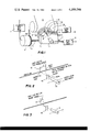
- FIG. 1 shows a printer apparatus adapted for use with the present invention
- FIG. 2 is a diagrammatic view illustrating the relationship between the hammer firing point and the impact point when the carrier is moving at a relatively fast rate
- FIG. 3 is a view similar to FIG. 2 except that that carrier is moving at a relatively slow rate;
- FIG. 4 is a graph showing the various velocities utilized to move the carrier a certain distance in order to provide an example of carriage movement during printing;
- FIG. 5 is a diagram illustrating the duration of certain delay periods and the print hammer control pulse widths utilized in this invention to control the printing hammer;
- FIG. 6 is a chart showing the relationship between the various delays and pulse widths employed to obtain a desired printing impact force and a desired escapement velocity of the printing carriage;
- FIG. 7 is a schematic diagram, in block form, of the circuitry for controlling the operation of the motors moving the carriage and the printing disc, and of the circuitry controlling the firing of the print hammer;
- FIG. 8 is a more detailed schematic diagram, in block form, of the circuitry for controlling the firing of the print hammer and the escapement of the carriage.
- FIG. 1 shows the main mechanical components of the present printer. They are shown somewhat schematically since such components are well known and the present invention is directed to the control mechanism for the two stepper motors 3 and 8 and the print hammer 10, and not to the mechanical components per se.
- a laterally sliding carrier 1 is mounted on a guide rod 1a and a lead screw 7 and carries a rotatable print wheel or disc 2 driven by a stepping motor 3.
- the carrier 1 is driven by lead screw 7 which is driven by a stepping motor 8.
- motor 8 could drive a belt which in turn could drive carrier 1.
- a type disc 2 comprises a disk having a number of movable type elements such as the flexible spokes or type fingers 9A, 9B, 9C, etc. Printing of any desired character is brought about by operating a print hammer 10, which is actuated by a solenoid 11, both of which are mounted on carrier 1. When the appropriate type finger approaches the print position, solenoid 11 actuates hammer 10 into contact with the selected type finger, driving it into contact with a paper 12 or other printing medium.
- An emitter wheel 13 attached to and rotating with type disc 2 cooperates with a magnetic sensor FB2 to produce a stream of emitter index pulses for controlling the operation of the printer.
- the emitter has a series of teeth each of which correspond to one finger 9A, 9B, 9C, etc.
- a homing pulse is generated for each revolution of the print wheel by a single tooth on another emitter (not shown).
- the printer controls can thus determine the angular position of type disc 2 at any time by counting the pulses received since the last homing pulse.
- a toothed emitter 15 is mounted on the shaft of the motor 8 and in conjunction with a transducer FB1 provides pulses which indicate the position of the carrier 1.
- Stepper motors 3 and 8 are activated by conventional drive circuits 21 and 22. Examples of the type of drive circuitry that could be used are shown in U.S. Pat. No. 3,636,429. A hammer solenoid 11 is actuated by a hammer drive circuit 23 which is also conventional.
- FIGS. 2 and 3 the relationship between the hammer firing point (at which time the firing of the print hammer is initiated), and the impact point on the printed line is illustrated.
- this relationship is illustrated when carrier 1 is moved at a relatively high velocity, whereas in FIG. 3 the same relationship is illustrated except that the carrier is being moved at a slower velocity.
- a relatively large lead indicated by the arrow L1 is required for petal 9a to imprint on the printed line at the impact point, whereas in FIG. 3 the line L1 is relatively shorter.
- the motion of the carrier can be chosen to move at a plurality of different velocities depending upon the character selection of the print wheel and, thus, the time required for the print wheel to move between adjacent characters.
- the movement of carriage 1 will likewise be at a velocity chosen among four separate velocities, V1, V2, V3, and V4.
- velocity V1 will be the slower of the velocities, velocity V2 faster than V1, velocity V3 faster than V2 and V1, and velocity V4 the fastest velocity.
- an important feature of the present invention is to provide for actuation of the print hammer in coordination with the selected carrier velocity in order to insure that when different carrier velocities are selected, the print hammer will be fired at the appropriate time in order to permit the printing petal to strike the printing medium at the desired impact point.
- a further important feature of the present invention is the provision for variation in the striking force of the print hammer on the selected print wheel petal, in accordance with character selection, in order to improve the print quality of the apparatus.
- variations in the striking force cause variations in the flight time of the petal from the point of impact by the hammer to the impact point to the printed line, it is further necessary to coordinate with the carriage velocity and hammer firing point with flight time of the petal for each different flight times (or striking forces) which may be selected.
- FIG. 4 illustrates a typical example of the excursion of carrier 1 at the four different velocities, V1, V2, V3, and V4, over a certain distance, which, in this instance, is approximately 1/2'.
- it is also desired to provide a plurality of firing pulse widths for the actuation of the print hammer such as pulse widths of the durations of P1, P2, and P3, as illustrated in FIG. 5.
- pulse P1 is of the shortest duration
- pulse P2 of a duration longer than pulse P1
- pulse P3 of a duration longer than pulses P1 and P2
- each are respectively initiated at the firing times FP1, FP2, and FP3.
- Each of the pulses respectively terminates at some time te prior to print point time tp. Since pulse P3 drives print hammer 10 the hardest, the flight time of the hammer from time FP3 to TP is the shortest as is the time from the end of the pulse, te, to print point time tp.
- the flight time of the hammer when actuated by pulse P2 is correspondingly longer than that required for pulse P3, and the flight time of the print hammer when actuated by pulse P1 is the longest for the three pulse durations indicated.
- FIG. 6 illustrates a delay table which lists the different delay times that can be chosen for appropriate combination of chosen carrier motion velocity and print hammer striking force.
- each of the hammer energy pulses P1, P2 and P3 can correspond to either light impact, medium impact, or hard impact, respectively, of the print hammer.
- V1, V2, V3 and V4 For each of the four velocities of the carrier, V1, V2, V3 and V4, one of the three impact conditions, light, medium, or hard (as represented by pulses P1, P2 or P3) can be chosen. Since this means twelve velocity-print impact combinations are possible in the example given in FIG. 6, it is necessary to provide for twelve separate delay times D1 through D12 to coordinate the firing time and flight time of the print hammer with the velocity of the carrier.
- a suitable microprocessor utilized to control the motion of the carrier and the motion of the print wheel, and the actuation of the print hammer can be programmed to provide an appropriate delay time D1 to D12 upon receipt of the hammer sync signal and upon receipt of information as to velocity of the carrier and the duration of the firing pulse chose.
- FIG. 7 a schematic diagram is illustrated of circuitry which may be utilized employing the principles of this invention discussed above in order to provide the appropriate control signals to drive circuit 21 (also referred herein as escapement motor drive circuit), to drive print wheel circuit 22, and to the hammer drive circuit 23.
- the data which is to be printed comes from a data source (not shown), which may be a conventional data buffer or keyboard input device such as a typewriter. Data from the data source is conducted to the input of a suitable computer or microprocessor, only the output of which is illustrated in FIG. 7, and the microprocessor can be any suitable commercially available microprocessor or computer such as the IBM system/7.
- the microprocessor receives the input data and will make certain calculations and then sends a series of binary numbers out on either an address bus 40 or a data bus 41 as illustrated in FIG. 7.
- the circuitry shown in FIG. 7 generates appropriate drive pulses to circuits 21, 22, and 23 in order to cause stepper motors 3 and 8 to move the carrier and the disc to the correct positions, and to activate the print hammer 10 in order to print the data supplied by the data source.
- the input signals to each of the drive circuits 21 and 22 include information indicating the direction which the stepper motor should move, and the number of steps to be moved, it being understood that one pulse is provided by the appropriate drive circuit for each step of the motors 3 and 8.
- the circuitry of this invention includes a plurality of buffer registers indicated generally by the reference numeral 42 which receive appropriate information from the microprocessor through address bus 40 and data bus 41.
- buffer registers 42 include an operating state register 43, which controls the velocity of movement of carrier 1, a hammer energy register 44 which stores data concerning initiation time and duration of the hammer energy pulse and the delay times D1 to D12, an escapement register 45 which receives and stores data concerning the extent of movement of carrier 1, and a selection register 46 which receives and stores data from the microprocessor concerning the selection of the characters on the printing wheel 2.
- data from data bus 41 of the microprocessor is routed through a data bus in gate 49 and data bus 50 to the respective inputs of the buffer registers 42.
- the microprocessor is also connected through the control bus 48, a data available line 51, and a data request line 52 to a sequence control circuit 53 which controls the sequence of operation of the circuitry of FIG. 7 and of the microprocessor, as hereinafter explained.
- buffer registers 42 Since printing is accomplished by the present invention while carrier 1 is in motion, it is necessary to provide buffer registers 42 in order that data from the processor may be stored therein prior to actual usage, to permit the processor to accumulate subsequent data and to permit new data to be stored in the buffer registers when the previously stored data has been dumped. In this manner, the data is available to the operating registers in circuitry FIG. 7 described below when needed in order to permit the continuous operation of the system.
- the circuit of FIG. 7 also includes a plurality of operating registers, illustrated generally by the reference numeral 60.
- operating registers 60 upon receipt of appropriate load command, receive and store the information contained in the buffer registers 42, thus permitting the buffer registers to then intake new data while the data in the operating registers is being acted on.
- an operating state output register 61 is provided to receive and store data from operating state register 43
- a hammer delay and energy register 62 is provided to receive stored data received from hammer energy register 44
- an escapement down counter is provided to receive and store data from escapement register 45
- a selection down counter 64 is provided to receive and store data from a selection register 46.
- the outputs of the respective registers are connected as shown in FIG. 7 to hammer control logic 65 for controlling the actuation of print hammer 10, to escapement control motor logic 66 for controlling the motion of carrier 1, and to selection motor control logic 67 for controlling the motion of print wheel 2.
- a control signal 53a from the microprocessor is conducted to sequence control circuit 53 and will cause sequence control circuit to start the sequence of operation of the printing apparatus of the invention.
- sequence control circuit 53 will advise the microprocessor through line 52 that buffer registers 42 are ready to review the next bank of data.
- the data available response of the microprocessor on line 51 initiates a control sequence whereby a data strobe signal from sequence control circuit 53 arms the buffer registers 42 for receipt of new data from the microprocessor.
- the appropriate register is addressed by the microprocessor through control bus 48 and when the proper address is received by the individual registers, the data for that register is conducted through ingate 49 and data bus 50 to be stored in the register.
- sequence control circuit 53 provides a load control signal on line 53b which is conducted from sequence control 53 to each of the operating registers 60 to permit the data stored in buffer registers 42 to be dumped into the operating registers 60. Once this is accomplished, sequence control signal 53 will then request new data of the processor which would then function to provide the next series of the data to be stored in buffer registers 42. Of course, while this is being done, the data in operating registers can be acted on.
- the escapement data stored in register 63 is conducted in a sequence of 12 bits to escapement decode circuit 70 which provides three output signals ESC1, ESC2 and ESC3. These signals represent the number of units of movement that the carrier is away from escapement zero, with ESC1 being equal to one unit from zero, ESC2 being two units from zero, and ESC3 being three units from zero.
- the information from which these signals are derived can come from sensor FB1 through input line 72 and each unit can be any predetermined number of pulses from sensor FB1.
- decode circuit 70 provides a fourth output at line 71a indicating that the escapement movement has reached zero point, and a fifth output which is indicated by line 71b and on which a signal is present when escapement has not reached zero.
- line 71b is high and a signal is received on line 72 from position indicator FB1
- an AND circuit 73 will provide an output to escapement motor control logic 66 to provide for movement of the motor. This movement will continue as long as no escapement zero signal on line 71b is high.
- the output signal ESC1 from escapement decode 70 which represents an escapement position one unit from zero, can be combined in an AND circuit 74a with velocity signal V1 from operating state output register 61, so that when the velocity of the escapement motor is at V1, and one unit from zero ESC1 has been reached, an output is provided on line 75 and conducted to OR circuit 76 which in turn provides an output 77 to an AND circuit 78 which is under control of a clock pulse on line 79.
- escapement unit ESC2 can be combined in an AND circuit 74b with signals from operating state output register 61 representing escapement velocities of either V2 or V3, (determined by OR circuit 61a) and escapement unit signal ESC3 can be combined in AND circuit 74c with escapement velocity signal V4.
- AND gate 78 which is armed by clock signal 79 will provide a hammer sync pulse on line 80. This is the same pulse that is indicated by t 0 in FIG.
- the delay down counter 62a which has been previously loaded with data indicating the delay time required for the period of time from the hammer sync pulse to initiation of the firing pulse (FP1, FP2, or FP3).
- the information stored in the delay down counter 62a can be delay number from 1 to 12 indicating one of twelve possible delay periods, and this number is contained in eight bits of data received.
- an output is provided through a circuit 81 (indicated as TMR0 or time zero) and this output is conducted to the input of an AND circuit 82 and a second AND circuit 83 as illustrated in FIG. 8.
- AND circuit 82 is also armed by a clock pulse, and receipt of the signal TMR0 from a circuit 81 will provide an output on line 84 which is conducted to the input of hammer pulse down counter 62b which determines the duration of the energy signal or pulse utilized to drive the hammer to actuation.
- counter 62b has previously been loaded with information from register 44 contained in 8 bits concerning whether or not the pulse width is to be one of three pulses, P1, P2, or P3, as previously noted with respect to the discussion of FIGS. 5 and 6.
- the output of counter 62b is inverted so that as long as the counter is still counting, and its output has not reached zero, a signal is provided by AND gate 85 (referred to as HPC not 0) and this output is conducted to AND gate 83.
- AND gate 83 is armed with these two signals.
- AND gate 83 requires a third input signal in order for the hammer to be actuated and it receives such on line 86. The absence of a signal on line 86 inhibits the firing of a hammer.
- the inhibit circuit illustrated in the event that a petal has not been selected such as a space movement of the carriage
- the hammer will be inhibited from striking the petal until it receives the next command that a petal has been selected.
- a start signal may be provided from sequence control circuit 53 to initiate the operation of the apparatus disclosed in FIGS. 7 and 8. However, once the sequence of operation is started and the various mechanical devices incorporated in the printer are in motion, the start pulse is ignored. Also, in the sequence of events utilized with the preferred embodiment of this invention disclosed, when escapement motor 8 reaches the zero position (indicated by the ESCO signal from escapement decode 70), this is the signal that the carrier is at the impact point and impact should have occurred. At this point the operating registers are ready to be reloaded and the mechanical system of the printer is ready to be moved to the next adjacent position.
- Pulse width tolerances are tightly controlled by the use of clocking that can be derived from the Miniprocessor system clock.
Landscapes
- Character Spaces And Line Spaces In Printers (AREA)
Priority Applications (2)
| Application Number | Priority Date | Filing Date | Title |
|---|---|---|---|
| US05/863,450 US4189246A (en) | 1977-12-22 | 1977-12-22 | Variable print-hammer control for on-the-fly-printing |
| CA000317969A CA1119732A (fr) | 1977-12-22 | 1978-12-14 | Regulateur de frappe pour imprimante a chariot mobile |
Applications Claiming Priority (1)
| Application Number | Priority Date | Filing Date | Title |
|---|---|---|---|
| US05/863,450 US4189246A (en) | 1977-12-22 | 1977-12-22 | Variable print-hammer control for on-the-fly-printing |
Publications (1)
| Publication Number | Publication Date |
|---|---|
| US4189246A true US4189246A (en) | 1980-02-19 |
Family
ID=25341121
Family Applications (1)
| Application Number | Title | Priority Date | Filing Date |
|---|---|---|---|
| US05/863,450 Expired - Lifetime US4189246A (en) | 1977-12-22 | 1977-12-22 | Variable print-hammer control for on-the-fly-printing |
Country Status (2)
| Country | Link |
|---|---|
| US (1) | US4189246A (fr) |
| CA (1) | CA1119732A (fr) |
Cited By (34)
| Publication number | Priority date | Publication date | Assignee | Title |
|---|---|---|---|---|
| US4259903A (en) * | 1978-10-11 | 1981-04-07 | International Business Machines Corporation | Circuit arrangement for synchronizing the times of occurrence of the print hammer impact with the arrival of the print type at the print position |
| WO1981002706A1 (fr) * | 1980-03-25 | 1981-10-01 | Phoenix Hydrocarbon Inc | Imprimante a couleurs et cassette a rubans multiples |
| US4307967A (en) * | 1979-03-04 | 1981-12-29 | Ricoh Company, Ltd. | Serial printing apparatus |
| US4332489A (en) * | 1980-11-24 | 1982-06-01 | International Business Machines Corporation | Print hammer actuating device |
| EP0042032A3 (en) * | 1980-06-16 | 1982-06-23 | International Business Machines Corporation | Method for controlling the driving intensity of a print hammer in an impact printer and impact printer embodying the method |
| US4347786A (en) * | 1979-10-01 | 1982-09-07 | International Business Machines Corporation | Impact printer hammer flight time and velocity sensing means |
| US4368666A (en) * | 1980-01-12 | 1983-01-18 | Hitachi Koki Company, Limited | Method and circuit arrangement for controlling print timing in a printing apparatus |
| US4372696A (en) * | 1980-05-20 | 1983-02-08 | Monarch Marking Systems, Inc. | High quality printer |
| US4384520A (en) * | 1980-09-16 | 1983-05-24 | Hitachi Koki Company, Limited | Device for controlling solenoids of high speed printer |
| US4405245A (en) * | 1979-07-24 | 1983-09-20 | Ricoh Company, Ltd. | Variable speed signal printing apparatus |
| US4410286A (en) * | 1981-06-16 | 1983-10-18 | International Business Machines Corporation | Printing complex characters |
| US4422781A (en) * | 1982-03-01 | 1983-12-27 | Centronics Data Computer Corp. | Printing apparatus and method variable velocity on-the fly printing |
| US4440079A (en) * | 1982-01-11 | 1984-04-03 | International Business Machines Corporation | Control system for timing hammers of impact printers |
| US4490055A (en) * | 1982-06-30 | 1984-12-25 | International Business Machines Corporation | Automatically adjustable delay function for timed typamatic |
| US4493570A (en) * | 1981-10-14 | 1985-01-15 | Ricoh Company, Ltd. | Control system for impact printer |
| US4558965A (en) * | 1980-10-31 | 1985-12-17 | Canon Kabushiki Kaisha | Printing apparatus controlling advancement of printing paper, actuation of a hammer, and advancement of an ink ribbon |
| EP0128290A3 (en) * | 1983-05-11 | 1986-02-19 | International Business Machines Corporation | Printing with a data stream including merged graphic and alphanumeric data |
| DE3441240A1 (de) * | 1984-11-12 | 1986-05-28 | Licentia Patent-Verwaltungs-Gmbh, 6000 Frankfurt | Verfahren zum koordinieren der drehbewegung eines auf einem schreibwerkwagen angeordneten typenrades mit der waehrend des anschlagens der typen auf die druckflaeche andauernden translatorischen bewegung des schreibwerkwagens |
| US4624591A (en) * | 1983-06-16 | 1986-11-25 | International Business Machines Corporation | Impact printer with type font elements having mid-line pitch change capability |
| US4627752A (en) * | 1983-10-07 | 1986-12-09 | Tokyo Electric Co., Ltd. | Daisy wheel printing device with variable hammer delay |
| US4638732A (en) * | 1985-01-18 | 1987-01-27 | Pitney Bowes Inc. | Sheet handling apparatus |
| US4644477A (en) * | 1983-08-31 | 1987-02-17 | Brother Industries, Ltd. | Printing apparatus |
| US4653945A (en) * | 1983-11-14 | 1987-03-31 | Tokyo Electric Co., Ltd. | Rotary wheel printing apparatus with controllable hammer striking force |
| US4687356A (en) * | 1984-07-02 | 1987-08-18 | Sharp Kabushiki Kaisha | Electronic printer with interleaved storage of print wheel position, hammer intensity, and carriage position data in read only memory |
| US4747709A (en) * | 1981-10-15 | 1988-05-31 | Canon Kabushiki Kaisha | Printing apparatus with variable impact pressure |
| US4758104A (en) * | 1984-07-06 | 1988-07-19 | Brother Kogyo Kabushiki Kaisha | Printing device |
| US4881835A (en) * | 1987-04-23 | 1989-11-21 | Brother Kogyo Kabushiki Kaisha | Printer having adjustable gap between print head and recording medium |
| US4940344A (en) * | 1984-07-30 | 1990-07-10 | Canon Kabushiki Kaisha | Printer having a variable interval between printing and carriage movement |
| US5039237A (en) * | 1987-06-02 | 1991-08-13 | Oki Electric Industry Co., Ltd. | Dot matrix print head drive method |
| US5040910A (en) * | 1984-12-24 | 1991-08-20 | Mannesmann Kienzle Gmbh | Printing device for the production of automatically readable script on documents |
| US5092692A (en) * | 1983-09-12 | 1992-03-03 | Canon Kabushiki Kaisha | Print pressure retrival from ascending order table |
| US5263994A (en) * | 1991-04-09 | 1993-11-23 | Brother Kogyo Kabushiki Kaisha | Printer having a plurality of printing modes |
| US5312193A (en) * | 1989-07-10 | 1994-05-17 | U.S. Philips Corporation | Control device for a matrix printer |
| US5322376A (en) * | 1980-10-31 | 1994-06-21 | Canon Kabushiki Kaishi | Serial printing apparatus including an error correcting capability and having a memory |
Citations (3)
| Publication number | Priority date | Publication date | Assignee | Title |
|---|---|---|---|---|
| US3858509A (en) * | 1972-07-10 | 1975-01-07 | Xerox Corp | Control logic for print wheel and hammer of high speed printing apparatus |
| US4030591A (en) * | 1970-01-29 | 1977-06-21 | International Business Machines Corporation | Controls for a movable disk printer |
| US4058195A (en) * | 1976-05-03 | 1977-11-15 | Xerox Corporation | Increment-decrement logic for serial printer |
-
1977
- 1977-12-22 US US05/863,450 patent/US4189246A/en not_active Expired - Lifetime
-
1978
- 1978-12-14 CA CA000317969A patent/CA1119732A/fr not_active Expired
Patent Citations (3)
| Publication number | Priority date | Publication date | Assignee | Title |
|---|---|---|---|---|
| US4030591A (en) * | 1970-01-29 | 1977-06-21 | International Business Machines Corporation | Controls for a movable disk printer |
| US3858509A (en) * | 1972-07-10 | 1975-01-07 | Xerox Corp | Control logic for print wheel and hammer of high speed printing apparatus |
| US4058195A (en) * | 1976-05-03 | 1977-11-15 | Xerox Corporation | Increment-decrement logic for serial printer |
Cited By (40)
| Publication number | Priority date | Publication date | Assignee | Title |
|---|---|---|---|---|
| US4259903A (en) * | 1978-10-11 | 1981-04-07 | International Business Machines Corporation | Circuit arrangement for synchronizing the times of occurrence of the print hammer impact with the arrival of the print type at the print position |
| US4307967A (en) * | 1979-03-04 | 1981-12-29 | Ricoh Company, Ltd. | Serial printing apparatus |
| US4405245A (en) * | 1979-07-24 | 1983-09-20 | Ricoh Company, Ltd. | Variable speed signal printing apparatus |
| US4347786A (en) * | 1979-10-01 | 1982-09-07 | International Business Machines Corporation | Impact printer hammer flight time and velocity sensing means |
| US4368666A (en) * | 1980-01-12 | 1983-01-18 | Hitachi Koki Company, Limited | Method and circuit arrangement for controlling print timing in a printing apparatus |
| WO1981002706A1 (fr) * | 1980-03-25 | 1981-10-01 | Phoenix Hydrocarbon Inc | Imprimante a couleurs et cassette a rubans multiples |
| US4403874A (en) * | 1980-03-25 | 1983-09-13 | Ramtek Corporation | Color printer and multi-ribbon cartridge therefor |
| US4372696A (en) * | 1980-05-20 | 1983-02-08 | Monarch Marking Systems, Inc. | High quality printer |
| EP0042032A3 (en) * | 1980-06-16 | 1982-06-23 | International Business Machines Corporation | Method for controlling the driving intensity of a print hammer in an impact printer and impact printer embodying the method |
| US4384520A (en) * | 1980-09-16 | 1983-05-24 | Hitachi Koki Company, Limited | Device for controlling solenoids of high speed printer |
| US5562355A (en) * | 1980-10-31 | 1996-10-08 | Canon Kabushiki Kaisha | Serial printing apparatus with sentence memory and display having correcting means |
| US4846593A (en) * | 1980-10-31 | 1989-07-11 | Canon Kabushiki Kaisha | Printing apparatus system with a plurality of interchangeable type units |
| US5322376A (en) * | 1980-10-31 | 1994-06-21 | Canon Kabushiki Kaishi | Serial printing apparatus including an error correcting capability and having a memory |
| US5484214A (en) * | 1980-10-31 | 1996-01-16 | Canon Kabushiki Kaisha | Serial printing apparatus including an error correcting capability and having a memory |
| US4558965A (en) * | 1980-10-31 | 1985-12-17 | Canon Kabushiki Kaisha | Printing apparatus controlling advancement of printing paper, actuation of a hammer, and advancement of an ink ribbon |
| US5529406A (en) * | 1980-10-31 | 1996-06-25 | Canon Kabushiki Kaisha | Document processing apparatus and method for printing a document read out of a memory |
| US5690435A (en) * | 1980-10-31 | 1997-11-25 | Canon Kabushiki Kaisha | Serial printing apparatus with sentence memory and display |
| US4332489A (en) * | 1980-11-24 | 1982-06-01 | International Business Machines Corporation | Print hammer actuating device |
| US4410286A (en) * | 1981-06-16 | 1983-10-18 | International Business Machines Corporation | Printing complex characters |
| US4493570A (en) * | 1981-10-14 | 1985-01-15 | Ricoh Company, Ltd. | Control system for impact printer |
| US4747709A (en) * | 1981-10-15 | 1988-05-31 | Canon Kabushiki Kaisha | Printing apparatus with variable impact pressure |
| US4440079A (en) * | 1982-01-11 | 1984-04-03 | International Business Machines Corporation | Control system for timing hammers of impact printers |
| US4422781A (en) * | 1982-03-01 | 1983-12-27 | Centronics Data Computer Corp. | Printing apparatus and method variable velocity on-the fly printing |
| US4490055A (en) * | 1982-06-30 | 1984-12-25 | International Business Machines Corporation | Automatically adjustable delay function for timed typamatic |
| EP0128290A3 (en) * | 1983-05-11 | 1986-02-19 | International Business Machines Corporation | Printing with a data stream including merged graphic and alphanumeric data |
| US4624591A (en) * | 1983-06-16 | 1986-11-25 | International Business Machines Corporation | Impact printer with type font elements having mid-line pitch change capability |
| US4644477A (en) * | 1983-08-31 | 1987-02-17 | Brother Industries, Ltd. | Printing apparatus |
| US5092692A (en) * | 1983-09-12 | 1992-03-03 | Canon Kabushiki Kaisha | Print pressure retrival from ascending order table |
| US4627752A (en) * | 1983-10-07 | 1986-12-09 | Tokyo Electric Co., Ltd. | Daisy wheel printing device with variable hammer delay |
| US4653945A (en) * | 1983-11-14 | 1987-03-31 | Tokyo Electric Co., Ltd. | Rotary wheel printing apparatus with controllable hammer striking force |
| US4687356A (en) * | 1984-07-02 | 1987-08-18 | Sharp Kabushiki Kaisha | Electronic printer with interleaved storage of print wheel position, hammer intensity, and carriage position data in read only memory |
| US4758104A (en) * | 1984-07-06 | 1988-07-19 | Brother Kogyo Kabushiki Kaisha | Printing device |
| US4940344A (en) * | 1984-07-30 | 1990-07-10 | Canon Kabushiki Kaisha | Printer having a variable interval between printing and carriage movement |
| DE3441240A1 (de) * | 1984-11-12 | 1986-05-28 | Licentia Patent-Verwaltungs-Gmbh, 6000 Frankfurt | Verfahren zum koordinieren der drehbewegung eines auf einem schreibwerkwagen angeordneten typenrades mit der waehrend des anschlagens der typen auf die druckflaeche andauernden translatorischen bewegung des schreibwerkwagens |
| US5040910A (en) * | 1984-12-24 | 1991-08-20 | Mannesmann Kienzle Gmbh | Printing device for the production of automatically readable script on documents |
| US4638732A (en) * | 1985-01-18 | 1987-01-27 | Pitney Bowes Inc. | Sheet handling apparatus |
| US4881835A (en) * | 1987-04-23 | 1989-11-21 | Brother Kogyo Kabushiki Kaisha | Printer having adjustable gap between print head and recording medium |
| US5039237A (en) * | 1987-06-02 | 1991-08-13 | Oki Electric Industry Co., Ltd. | Dot matrix print head drive method |
| US5312193A (en) * | 1989-07-10 | 1994-05-17 | U.S. Philips Corporation | Control device for a matrix printer |
| US5263994A (en) * | 1991-04-09 | 1993-11-23 | Brother Kogyo Kabushiki Kaisha | Printer having a plurality of printing modes |
Also Published As
| Publication number | Publication date |
|---|---|
| CA1119732A (fr) | 1982-03-09 |
Similar Documents
| Publication | Publication Date | Title |
|---|---|---|
| US4189246A (en) | Variable print-hammer control for on-the-fly-printing | |
| US4030591A (en) | Controls for a movable disk printer | |
| US4232975A (en) | Print hammer control | |
| US4159882A (en) | High quality printer | |
| US4410286A (en) | Printing complex characters | |
| US3168182A (en) | Type wheel shifting and impacting means in high speed printers | |
| US4147967A (en) | Apparatus and method for controlling the velocity of a moveable member | |
| US4178108A (en) | Apparatus for space synchronizing carrier and rotatable print disk positions in on-the-fly printing | |
| US4347786A (en) | Impact printer hammer flight time and velocity sensing means | |
| US3312174A (en) | Variable cycle control system for a high speed printer | |
| US3899968A (en) | Print media identification code | |
| US3938641A (en) | Control system for high speed printer | |
| EP0042032B1 (fr) | Méthode pour commander la durée de déplacement d'un marteau d'impression dans une imprimante à percussion et imprimante dans laquelle ladite méthode est utilisée | |
| CA1056207A (fr) | Commande pour imprimante a disque mobile | |
| EP0105095A2 (fr) | Imprimante avec vitesse d'impression optimale | |
| US3810195A (en) | Helical bar printer logic circuitry | |
| US3651914A (en) | Asynchronous printer | |
| US3773161A (en) | High speed serial printer with plural hammers | |
| US3834304A (en) | Helical bar printer and hammer therefor | |
| US3342127A (en) | High speed printing device with reciprocable type bar | |
| US4473313A (en) | Timing control method for controlling reciprocating print head | |
| CA1128446A (fr) | Dispositif pour synchroniser la vitesse du chariot et la selection du caractere d'impression en impression "a la volee" | |
| US4175488A (en) | Printer | |
| JPS5829237B2 (ja) | シリアルブリンタ | |
| US3687071A (en) | Timing mechanism for printing apparatus employing flying printing action |
Legal Events
| Date | Code | Title | Description |
|---|---|---|---|
| AS | Assignment |
Owner name: IBM INFORMATION PRODUCTS CORPORATION, 55 RAILROAD Free format text: ASSIGNMENT OF ASSIGNORS INTEREST.;ASSIGNOR:INTERNATIONAL BUSINESS MACHINES CORPORATION;REEL/FRAME:005678/0098 Effective date: 19910326 Owner name: MORGAN BANK Free format text: SECURITY INTEREST;ASSIGNOR:IBM INFORMATION PRODUCTS CORPORATION;REEL/FRAME:005678/0062 Effective date: 19910327 |