US4196906A - Video disc player - Google Patents
Video disc player Download PDFInfo
- Publication number
- US4196906A US4196906A US05/964,531 US96453178A US4196906A US 4196906 A US4196906 A US 4196906A US 96453178 A US96453178 A US 96453178A US 4196906 A US4196906 A US 4196906A
- Authority
- US
- United States
- Prior art keywords
- carriage
- record
- caddy
- player
- turntable
- Prior art date
- Legal status (The legal status is an assumption and is not a legal conclusion. Google has not performed a legal analysis and makes no representation as to the accuracy of the status listed.)
- Expired - Lifetime
Links
- 230000002596 correlated effect Effects 0.000 claims abstract description 4
- 238000003780 insertion Methods 0.000 claims description 17
- 230000037431 insertion Effects 0.000 claims description 17
- 238000010276 construction Methods 0.000 claims description 5
- 230000007246 mechanism Effects 0.000 abstract description 26
- 230000000717 retained effect Effects 0.000 abstract description 10
- 241001422033 Thestylus Species 0.000 description 16
- 230000000994 depressogenic effect Effects 0.000 description 9
- 230000000694 effects Effects 0.000 description 9
- 238000013519 translation Methods 0.000 description 9
- 230000000284 resting effect Effects 0.000 description 8
- 230000000875 corresponding effect Effects 0.000 description 4
- 238000012546 transfer Methods 0.000 description 3
- 230000002457 bidirectional effect Effects 0.000 description 2
- 230000008878 coupling Effects 0.000 description 2
- 238000010168 coupling process Methods 0.000 description 2
- 238000005859 coupling reaction Methods 0.000 description 2
- 239000000428 dust Substances 0.000 description 2
- 238000000605 extraction Methods 0.000 description 2
- 230000002093 peripheral effect Effects 0.000 description 2
- 238000012545 processing Methods 0.000 description 2
- 230000009286 beneficial effect Effects 0.000 description 1
- 239000011248 coating agent Substances 0.000 description 1
- 238000000576 coating method Methods 0.000 description 1
- 238000004891 communication Methods 0.000 description 1
- 238000013461 design Methods 0.000 description 1
- 238000006073 displacement reaction Methods 0.000 description 1
- 230000007717 exclusion Effects 0.000 description 1
- 238000009877 rendering Methods 0.000 description 1
- 230000001360 synchronised effect Effects 0.000 description 1
- 230000000007 visual effect Effects 0.000 description 1
Images


Classifications
-
- G—PHYSICS
- G11—INFORMATION STORAGE
- G11B—INFORMATION STORAGE BASED ON RELATIVE MOVEMENT BETWEEN RECORD CARRIER AND TRANSDUCER
- G11B17/00—Guiding record carriers not specifically of filamentary or web form, or of supports therefor
- G11B17/02—Details
- G11B17/04—Feeding or guiding single record carrier to or from transducer unit
- G11B17/041—Feeding or guiding single record carrier to or from transducer unit specially adapted for discs contained within cartridges
- G11B17/049—Insertion of discs having to be extracted from the cartridge prior to recording or reproducing
-
- G—PHYSICS
- G11—INFORMATION STORAGE
- G11B—INFORMATION STORAGE BASED ON RELATIVE MOVEMENT BETWEEN RECORD CARRIER AND TRANSDUCER
- G11B17/00—Guiding record carriers not specifically of filamentary or web form, or of supports therefor
- G11B17/02—Details
- G11B17/022—Positioning or locking of single discs
- G11B17/028—Positioning or locking of single discs of discs rotating during transducing operation
- G11B17/032—Positioning by moving the door or the cover
Definitions
- This invention generally relates to record players, and more particularly, it relates to players suitable for use with a record caddy.
- information is stored on a disc record in the form of geometric variations in the bottom of a continuous spiral groove disposed on the record surface.
- the variations in capacitance between an electrode incorporated in a groove-riding stylus and a conductive coating disposed on the record surface are sensed to reproduce the stored information.
- a capacitance-type video disc system is illustratively disclosed in U.S. Pat. No. 3,842,194 (Clemens).
- the carriage is typically mounted for side-to-side motion and the direction of caddy insertion is from front-to-back, a direction which is orthogonal to the carriage path.
- Such configuration imposes several constraints on player design and construction: for example, it is necessary that the starting position of the carriage is beyond the record periphery; one of the caddy guiding rails is mounted on the carriage to prevent interference thereof with the motion of the carriage toward the record center; a separate mechanism is needed to return the carriage to the starting position subsequent to playback; and a stylus landing adjustment mechanism is necessary to insure that the stylus is lowered precisely over the beginning of the recorded band during travel of the carriage from an off-record starting position toward a position overlying the record.
- the player incorporating the principles of the present invention, overcomes hereinbefore mentioned constraints.
- the player includes a housing provided with an input slot into which a record caddy is inserted along a path for loading a record therein.
- a turntable centers and rotatably supports a loaded record.
- the player is equipped with a mechanism for translating a pickup carriage along a second path extending substantially parallel to the caddy path at a speed correlated to the speed of rotation of the turntable during playback.
- the direction of translation of the carriage during playback is opposite to the direction of the caddy insertion.
- the location of the caddy path relative to the carriage path is such that the caddy engages the carriage, when the carriage is at a position other than at a starting position, during a caddy insertion to reset the carriage at the starting position.
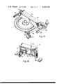
- FIG. 1 is a plan view of a video record player incorporating the principles of the present invention
- FIG. 2 is a perspective end view of the player of FIG. 1, with a depressible platform being shown in the raised position;
- FIG. 3 is a perspective end view of the player of FIGS. 1 and 2, with the depressible platform being shown in the lowered position;
- FIGS. 4 and 5 depict a record caddy, comprising a jacket and a record retaining member, suitable for use with the player of FIGS. 1-3;
- FIG. 6 illustrates a record extracting mechanism disposed in the player of FIGS. 1-3;
- FIGS. 7 and 8 show the operation of the record extracting mechanism of FIG. 6
- FIGS. 9 and 10 demonstrate the sequence involved in transferring a record, resting on the depressible platform of FIGS. 1-3, to the player turntable;
- FIGS. 11-13 illustrate a mechanical toggle switch suitable for use with a pickup carriage translating mechanism provided in the player of FIGS. 1-3;
- FIG. 14 shows an arrangement suitable for operating the toggle switch of FIGS. 11-13 by means of controls provided at the input end of the player;
- FIG. 15 depicts an alternate carriage translating mechanism suitable for use with the player of FIGS. 1-3.
- FIG. 16 illustrates a stylus lifting/lowering apparatus suitable for use with the player of FIGS. 1-3.
- a video disc player 20 includes a housing 22 which is provided with an input slot 24 at the front end thereof, through which a record caddy is inserted for loading an enclosed record into the player.
- a turntable 26 includes a record centering spindle 28, and a soft annular pad 30 for supporting the record. The turntable diameter is made less than the record diameter, and the soft annular pad supports the record in the grooved area.
- a platform 34 mounted on a shaft 36 which is located at the non-input end of the housing 22, is subject to motion between an elevated position (FIG. 2) and a depressed position (FIG. 3).
- a pair of rails 38 and 40 are disposed on the platform 34.
- the rails have grooves 42 and 44 for guiding insertion of a caddy into the housing along a path.
- the front ends of the caddy guiding grooves are aligned with the input slot 24 when the platform is occupying the elevated position for permitting insertion of a caddy into the player.
- the record caddy 50 comprises an outer jacket 52 and a record retaining member 54 removably located within the jacket.
- the retaining member comprises (1) an annular portion 56, that encircles the enclosed record 58, and (2) a spine portion 60, which serves as a closure to keep dust and debris from entering the record enclosing cavity.
- the spine has an opening 62 into which the latch arms 70 and 72 of a record extracting mechanism 74 (FIG. 1) protrude during arrival of a record caddy at a fully inserted position in the player to effect record removal during subsequent caddy withdrawal.
- the record extracting mechanism 74 is mounted on the platform 34.
- the extracting mechanism 74 includes latch arms 70 and 72 pivotally secured to a platform-mounted bracket 76.
- the latch arms are alternated between an open condition (FIGS. 6 and 7) and a closed condition (FIG. 8), in response to each caddy arrival at the fully inserted position in the player.
- the arrangement for rendering the extracting mechanism caddy responsive includes a pivotally-mounted actuating arm 78 disposed in the caddy path.
- the actuating arm advances a ratchet 80, carrying a square-shaped cam 82, through 45 degrees each time a cover arrives at a fully inserted position in the player.
- Each advancement of the square-shaped cam changes the condition of latch arms from the condition they occupied prior to cover insertion to the other condition thereof.
- Springs (not shown) are provided for returning the actuating arm to the rest position thereof, and to bias the latch arms into engagement with the square-shaped cam 82.
- a pawl (not shown) is provided to prevent the ratchet from rotating in the reverse direction when the actuating arm is returned to its rest position.
- U.S. Pat. No. 4,109,919 discloses a suitable caddy-actuated record extracting mechanism.
- the platform With the record resting thereon, is raised (FIG. 9).
- the inner diameter of an opening 90 in the platform 34 is sufficiently less than the record diameter to positively insure lifting of the retained record during upward motion of the platform.
- the platform is provided with a set of depressible lifting pads 92, 93, 94, 95 and 96 (FIG. 1) to align the record resting thereon with the caddy guiding grooves 42 and 44 to cause return of the record into an empty caddy during insertion thereof into the player.
- the leading edge thereof depressed the lifting pads to allow forward motion of the caddy.
- the engagement of the caddy with the actuating arm 78 reindexes the latch arms to the closed condition (FIG. 8), thereby freeing the record from the player. Subsequent caddy withdrawal removes the enclosed record therewith.
- the rails 38 and 40 are further provided with a second set of grooves 100 and 102 (FIGS. 2 and 3) for guiding a carriage 104 along a second path substantially parallel to the caddy path (front-and-back).
- the carriage is provided with a pair of projections (not shown), which are respectively received in the carriage guiding grooves.
- a pair of racks 110 and 112 are respectively secured to the platform rails 38 and 40.
- a shaft 114, carrying a set of pinions 116 and 118, is rotatably secured to the carriage 104 (FIG. 1).
- a respective one of the pinions engages a respective one of the racks to ensure that the carriage path lies radially of a turntable-supported record throughout the operating range thereof.
- the carriage Prior to playback, the carriage is restored to a starting position.
- the resetting of the carriage to the starting position is done automatically when a caddy is inserted, for example, to retrieve a record, resting on the platform while it is disposed in the raised position, from the player.
- the location of the caddy path relative to the carriage path is such that a caddy engages the carriage during insertion thereof into the player.
- the player is dimensioned such that the arrival of the carriage-engaging caddy at the fully inserted position in the player coincides with the arrival of the engaged carriage at the starting position.
- the platform For playback, the platform, with a retained record resting thereon, is depressed to transfer the record to the turntable.
- the carriage is translated during playback along the rails in a direction opposite to the direction of caddy insertion in correlation with the speed of rotation of the turntable.
- the carriage In addition to normal correlated translation of the carriage during playback, the carriage is translatable in either direction at a speed independent of the speed of rotation of the turntable during active search.
- a turntable-driven pulley 150 and a thumbwheel-driven pulley 152 are also loosely mounted on the platform shaft 36 for motion independent thereof.
- the play belt driving pulley 136 and the search belt driving pulley 140 are respectively secured to the turntable-driven pulley 150 and the thumbwheel-driven pulley 152 for rotation therewith.
- the stylus lifting/lowering apparatus 170 includes a stylus arm rest 172 mounted for motion between an elevated position and a depressed position.
- the stylus arm rest in the elevated position supports the stylus arm 108 (FIG. 1) in a manner precluding stylus/record contact.
- the stylus arm rest in the depressed position permits the stylus arm to occupy a lowered position.
- the lowered position of the stylus arm is such that the stylus/record contact is established when the carriage is in the over-record play position.
- An electromagnet 174 is energized to repel a permanent magnet 176 secured to the stylus arm rest to dispose the stylus arm rest in the depressed position.
- a leaf spring 178 secured to the stylus arm rest lifts the stylus 107 off the record when the electromagnet is deenergized.
- a selectively actuated plunger 179 depresses the stylus arm rest when actuated.
- U.S. Pat. No. 4,053,161 (Bleazey, et al.), discloses such stylus lifting/lowering apparatus.
- the mechanical toggle switch 134 is thrown into an active search mode to connect the carriage to the variable speed, bidirectional search belt 132 to the exclusion of the constant speed, unidirectional play belt 130.
- the stylus lifting/lowering apparatus permits stylus/record engagement.
- the carriage is translated at a rapid rate in the forward direction by rotating the thumbwheel 160 at appropriate speed in the required direction, while the stylus is allowed to ride on the record.
- the reverse motion can be obtained by translating the carriage in the reverse direction (i.e., away from the turntable center or toward the starting position).
- stop motion effect the carriage is allowed to remain stationary, thereby causing the groove-riding stylus to repetitively trace a selected set of groove convolutions.
- the toggle switch includes a block 180 secured to the platform-mounted carriage for translation therewith.
- the block has a pair of surfaces 182 and 184 defining a slot 186 through which the upper runs of the play and the search belts pass.
- the block is equipped with a recess 188 in communication with the top surface 182.
- a bifurcated plate 190 is mounted in the recess for arcuate motion about a pin 192 to selectively occupy the above-mentioned three positions.
- the play mode the upper run of the play belt 130 is squeezed between the toggle plate and the bottom surface 184 (FIG. 12).
- the search mode the upper run of the search belt 132 is held between the toggle plate and the bottom surface 184 (FIG. 13).
- the carriage is freed from both belts (FIG. 11).
- the switch actuating mechanism includes a pin 194 rotatably secured to the carriage-mounted block.
- An eccentric protrusion 196 is disposed at one end of the pin 194 for reception in a cutout 198 provided in the toggle plate 190.
- the position and orientation of the pin 194 relative to the toggle plate is such that the rotation of the pin effects pivotal motion of the toggle plate.
- a mode select lever 200 is secured to the pin 194 to selectively dispose the toggle plate in a selected one of the modes.
- FIG. 14 One such arrangement 210 is illustrated in FIG. 14. As shown therein, the mode selection lever 200 is curled upward at the free end thereof to provide an offset tab 212. A flap 214 is swingably mounted on the platform for arcuate motion about an axis lying parallel to the carriage path. A torsional spring 216 is provided to bias the mode selection lever to occupy an extreme position adjacent to the flap, whereby the carriage 104 is connected to play belt 130.
- the flap is rotated to a first extent (corresponding to the midway position of the toggle plate 190) and a second extent (corresponding to the outer extreme position of the toggle plate) in anti-clockwise direction (when viewed from the input end) to, respectively, set the toggle switch in the pause mode, wherein the carriage is released from both belts, and the search mode, wherein the carriage is under the influence of the search belt 132.
- An extension 220 is disposed on the flap 214 at the non-input end of the player for cooperation with struts 222 and 224.
- the struts 222 and 224 are actuated, respectively, by a pause button 226 and a search button 228 (FIG. 1) to cause the flap to, respectively, rotate to the first and the second extent.
- operation of the pause button and the search button indexes the toggle switch, respectively, into the pause mode and the search mode.
- the mode selection buttons are disposed on the front instrument panel, and are of push-on/push-off variety.
- the flat flap 214 is additionally equipped with a second extension 232 at the input end of the player for cooperation with a stationary overhanging member 234.
- the relative location of the stationary member is such that, when the platform 34 is raised to the elevated position, the stationary member depresses the second extension 232 to an extent that disposes the toggle switch into the pause mode, thereby freeing the carriage from both belts.
- the action of the stationary member on the flap when the platform is raised allows restoration of the carriage to the starting position, with freedom from interference by the carriage translating mechanism, during insertion of an empty caddy into the player for record retrieval.
- a function selection lever 250 secured to a rotatably mounted wheel 252, extends through a slot provided in the front instrument panel of the player.
- the function selection lever is moved to the positions shown in FIGS. 2 and 3, respectively, to raise and lower the platform.
- the front ends of the caddy guiding grooves 42 and 44 are aligned with the input slot to permit caddy insertion and extraction.
- the depression of the platform, with a retained record resting thereon, effects transfer of the retained record to the turntable for playback.
- the function selection lever may also serve to shut off power to the player, for example, when it is shifted to a position beyond the caddy in/out position (FIG. 2).
- the linkage between the function selection lever and the platform includes a pair of spaced levers 264 and 266 secured to a rotatably mounted shaft 268.
- a set of platform-engaging rollers 270 and 272 are respectively disposed at the free ends of the spaced levers.
- an endless toothed belt 274 is disposed about a toothed pulley 276, securely mounted on the shaft 268, and another toothed pulley 278, mounted coaxially with the function selection wheel for rotation therewith.
- the relative angular location of the spaced levers 264 and 266 is such that the motion of the function selection lever between the two positions causes corresponding motion of the platform between the elevated and the depressed position.
- a rotatably-mounted dial 290 (FIG. 1), bearing an indicia indicative of the respective playing times associated with distance traveled by the carriage from a starting position, is visible through a readout window provided in the front instrument panel of the player.
- a cord 292 extends between the carriage 104 and the indicia bearing dial such that the displacement of the carriage along the guiding rails effects synchronized rotation of the dial.
- a torsion spring 294 is disposed about the axis of rotation of the dial such that it gets coiled during translation of the carriage away from the starting position, whereby energy is stored in the torsion spring. The coiled spring applies a force to the carriage in a sense urging carriage travel toward the starting position.
- the applied force aids resetting of the carriage to the starting position, when it is at a position other than the starting position, during a caddy insertion.
- the cord 292 is passed over a grooved pulley 296 and another grooved pulley 298.
- the pulley 298 is coaxially mounted on the platform shaft.
- One end of the cord is fastened to the carriage-mounted block 180, and a portion of the other end thereof is wrapped around the stem portion of the dial.
- the stiffness of the torsion spring is selected to give the desired feel to the user of the player as he inserts a caddy into the player to restore the carriage to the starting position.
- FIG. 15 An alternate carriage translating mechanism is shown in FIG. 15. As shown therein, a spiral groove 310 is disposed on the periphery of a shaft 312 rotatably secured to the carriage 314.
- a cord 316 has a portion wrapped around the carriage shaft along the spiral groove therein. The cord, moreover, has further portions respectively passing over a grooved, turntable-driven pulley 318 and an idler pulley 320.
- a pair of pinions 322 and 324 are secured to the respective ends of the carriage shaft for engagement with platform-mounted racks 326 and 328.
- a drive chain 330 rotates the turntable-driven pulley at a speed such that the carriage is translated in synchronism with a pickup stylus riding in an information bearing track disposed on the turntable-supported record.
- the diameter of the peripheral groove in the carriage shaft is varied in correspondence with the variation in the record pitch, thereby providing precise carriage translation throughout the operating range.
- the input slot is covered with a flap for keeping dust and debris from entering the record chamber in the player.
- the flap uncovers the input slot to allow caddy insertion and extraction. In other modes of the player, the flap remains closed.
- both the caddy guiding grooves and the carriage guiding grooves are integrally molded with the platform to provide a single-main-frame construction. This permits a precise positioning of the caddy relative to the carriage and the carriage relative to the turntable throughout the operating range.
- the mounting of the play belt driving pulley 136, the search belt driving pulley 140, the turntable-driven pulley 150, the thumbwheel-driven pulley 152 and the grooved pulley 298 on the platform shaft 36 permits platform motion without disturbing the rest of the player system.
Landscapes
- Feeding And Guiding Record Carriers (AREA)
Priority Applications (18)
| Application Number | Priority Date | Filing Date | Title |
|---|---|---|---|
| CA000320544A CA1138566A (fr) | 1978-02-13 | 1979-01-30 | Lecteur de disques video |
| AU43933/79A AU528815B2 (en) | 1978-02-13 | 1979-02-05 | Video disc player |
| SE7901042A SE7901042L (sv) | 1978-02-13 | 1979-02-06 | Videoskivspelare |
| FI790386A FI790386A7 (fi) | 1978-02-13 | 1979-02-06 | Videoskivspelare |
| IT19944/79A IT1110234B (it) | 1978-02-13 | 1979-02-06 | Riproduttore di videodischi |
| AT0098179A AT368310B (de) | 1978-02-13 | 1979-02-09 | Plattenspieler |
| GB7904853A GB2015237B (en) | 1978-02-13 | 1979-02-12 | Video disc player |
| MX79100652U MX4240E (es) | 1978-02-13 | 1979-02-12 | Mejoras en reproductor de discos de vidio |
| DK58279A DK58279A (da) | 1978-02-13 | 1979-02-12 | Videopladespiller |
| DD79210979A DD142104A5 (de) | 1978-02-13 | 1979-02-12 | Plattenspieler |
| KR1019790000411A KR830000381B1 (ko) | 1978-02-13 | 1979-02-12 | 레코드 플레이어 |
| FR7903482A FR2417161A1 (fr) | 1978-02-13 | 1979-02-12 | Tourne-disque destine a recevoir un disque muni de son enveloppe |
| NL7901113A NL7901113A (nl) | 1978-02-13 | 1979-02-12 | Weergeefinrichting voor schijfvormige videoplaten. |
| BR7900831A BR7900831A (pt) | 1978-02-13 | 1979-02-12 | Toca-discos para uso com um carregador de discos |
| DE19792905325 DE2905325A1 (de) | 1978-02-13 | 1979-02-13 | Plattenspieler |
| JP1593679A JPS54115124A (en) | 1978-02-13 | 1979-02-13 | Record disk player |
| ES477661A ES477661A1 (es) | 1978-02-13 | 1979-02-13 | Perfeccionamientos en aparatos de reproduccion de videodisco. |
| HK63/83A HK6383A (en) | 1978-02-13 | 1983-02-17 | Record player for use with caddy |
Applications Claiming Priority (2)
| Application Number | Priority Date | Filing Date | Title |
|---|---|---|---|
| GB573778 | 1978-02-13 | ||
| GB05737/78 | 1978-02-13 |
Publications (1)
| Publication Number | Publication Date |
|---|---|
| US4196906A true US4196906A (en) | 1980-04-08 |
Family
ID=9801702
Family Applications (1)
| Application Number | Title | Priority Date | Filing Date |
|---|---|---|---|
| US05/964,531 Expired - Lifetime US4196906A (en) | 1978-02-13 | 1978-11-29 | Video disc player |
Country Status (5)
| Country | Link |
|---|---|
| US (1) | US4196906A (fr) |
| BE (1) | BE874078A (fr) |
| MY (1) | MY8300168A (fr) |
| PL (1) | PL213381A1 (fr) |
| ZA (1) | ZA79500B (fr) |
Cited By (12)
| Publication number | Priority date | Publication date | Assignee | Title |
|---|---|---|---|---|
| USD263138S (en) | 1980-03-17 | 1982-02-23 | Victor Company Of Japan, Limited | Disk player for video/audio pre-recorded cartridges, or similar article |
| DE3118106A1 (de) * | 1980-05-09 | 1982-02-25 | RCA Corp., 10020 New York, N.Y. | "video-plattenspieler" |
| DE3121862A1 (de) * | 1980-06-06 | 1982-03-04 | RCA Corp., 10020 New York, N.Y. | "vorrichtung zum ausrichten des schlittens fuer den abtaststift eines videoplattenspielers" |
| DE3117921A1 (de) * | 1980-05-09 | 1982-04-22 | RCA Corp., 10020 New York, N.Y. | Hoehenverstellvorrichtung fuer den plattenteller eines plattenabspielgeraetes |
| US4387454A (en) * | 1980-03-31 | 1983-06-07 | Victor Company Of Japan, Ltd. | Disc-shaped recording medium reproducing apparatus |
| US4390978A (en) * | 1981-06-30 | 1983-06-28 | Rca Corporation | Carriage translating mechanism for video disc player |
| US4408321A (en) * | 1980-04-28 | 1983-10-04 | Victor Company Of Japan, Ltd. | Disc-shaped recording medium reproducing apparatus |
| US4410973A (en) * | 1980-08-20 | 1983-10-18 | Victor Company Of Japan, Ltd. | Rotary recording medium reproducing apparatus having a switch mechanism for detecting return of a jacket opening enlarging mechanism |
| US4439852A (en) * | 1982-05-03 | 1984-03-27 | Rca Corporation | Disc player having record handling apparatus |
| US4486874A (en) * | 1984-03-28 | 1984-12-04 | Rca Corporation | Carriage-actuated disc handling apparatus for video disc player |
| US4493070A (en) * | 1984-05-07 | 1985-01-08 | Rca Corporation | Video disc player having carriage drive mechanism |
| US4500983A (en) * | 1981-07-28 | 1985-02-19 | Victor Company Of Japan, Ltd. | Rotary recording medium reproducing apparatus |
Citations (4)
| Publication number | Priority date | Publication date | Assignee | Title |
|---|---|---|---|---|
| CA538149A (fr) * | 1957-03-12 | N.V. Philips Gloeilampenfabrieken | Phonographe avec pick-up commande par l'insertion de disque | |
| US2866647A (en) * | 1953-04-10 | 1958-12-30 | Mc Graw Edison Co | Dictating machine |
| US4113262A (en) * | 1976-12-20 | 1978-09-12 | Rca Corporation | Record support and alignment apparatus for a video disc player |
| US4124866A (en) * | 1976-12-06 | 1978-11-07 | Rca Corporation | Video disc insertion/extraction system for a video disc player |
-
1978
- 1978-11-29 US US05/964,531 patent/US4196906A/en not_active Expired - Lifetime
-
1979
- 1979-02-06 ZA ZA79500A patent/ZA79500B/xx unknown
- 1979-02-09 BE BE193388A patent/BE874078A/fr not_active IP Right Cessation
- 1979-02-12 PL PL21338179A patent/PL213381A1/xx unknown
-
1983
- 1983-12-30 MY MY168/83A patent/MY8300168A/xx unknown
Patent Citations (4)
| Publication number | Priority date | Publication date | Assignee | Title |
|---|---|---|---|---|
| CA538149A (fr) * | 1957-03-12 | N.V. Philips Gloeilampenfabrieken | Phonographe avec pick-up commande par l'insertion de disque | |
| US2866647A (en) * | 1953-04-10 | 1958-12-30 | Mc Graw Edison Co | Dictating machine |
| US4124866A (en) * | 1976-12-06 | 1978-11-07 | Rca Corporation | Video disc insertion/extraction system for a video disc player |
| US4113262A (en) * | 1976-12-20 | 1978-09-12 | Rca Corporation | Record support and alignment apparatus for a video disc player |
Cited By (12)
| Publication number | Priority date | Publication date | Assignee | Title |
|---|---|---|---|---|
| USD263138S (en) | 1980-03-17 | 1982-02-23 | Victor Company Of Japan, Limited | Disk player for video/audio pre-recorded cartridges, or similar article |
| US4387454A (en) * | 1980-03-31 | 1983-06-07 | Victor Company Of Japan, Ltd. | Disc-shaped recording medium reproducing apparatus |
| US4408321A (en) * | 1980-04-28 | 1983-10-04 | Victor Company Of Japan, Ltd. | Disc-shaped recording medium reproducing apparatus |
| DE3118106A1 (de) * | 1980-05-09 | 1982-02-25 | RCA Corp., 10020 New York, N.Y. | "video-plattenspieler" |
| DE3117921A1 (de) * | 1980-05-09 | 1982-04-22 | RCA Corp., 10020 New York, N.Y. | Hoehenverstellvorrichtung fuer den plattenteller eines plattenabspielgeraetes |
| DE3121862A1 (de) * | 1980-06-06 | 1982-03-04 | RCA Corp., 10020 New York, N.Y. | "vorrichtung zum ausrichten des schlittens fuer den abtaststift eines videoplattenspielers" |
| US4410973A (en) * | 1980-08-20 | 1983-10-18 | Victor Company Of Japan, Ltd. | Rotary recording medium reproducing apparatus having a switch mechanism for detecting return of a jacket opening enlarging mechanism |
| US4390978A (en) * | 1981-06-30 | 1983-06-28 | Rca Corporation | Carriage translating mechanism for video disc player |
| US4500983A (en) * | 1981-07-28 | 1985-02-19 | Victor Company Of Japan, Ltd. | Rotary recording medium reproducing apparatus |
| US4439852A (en) * | 1982-05-03 | 1984-03-27 | Rca Corporation | Disc player having record handling apparatus |
| US4486874A (en) * | 1984-03-28 | 1984-12-04 | Rca Corporation | Carriage-actuated disc handling apparatus for video disc player |
| US4493070A (en) * | 1984-05-07 | 1985-01-08 | Rca Corporation | Video disc player having carriage drive mechanism |
Also Published As
| Publication number | Publication date |
|---|---|
| ZA79500B (en) | 1980-02-27 |
| PL213381A1 (fr) | 1980-05-05 |
| MY8300168A (en) | 1983-12-31 |
| BE874078A (fr) | 1979-05-29 |
Similar Documents
| Publication | Publication Date | Title |
|---|---|---|
| US4196906A (en) | Video disc player | |
| US4723185A (en) | Recording and/or reproducing apparatus | |
| US5737293A (en) | Disc loading apparatus for loading optical discs in a cartridge or without | |
| US5067116A (en) | Automatic disc changer apparatus | |
| US4220339A (en) | Caddy-actuated declutching mechanism for video disc player | |
| US4326284A (en) | Video disc player having turntable assist apparatus | |
| US4216969A (en) | Carriage translating apparatus for video disc player | |
| US4191381A (en) | Apparatus for facilitating carriage return in video disc player | |
| US4439852A (en) | Disc player having record handling apparatus | |
| US4191380A (en) | Video disc player having unitary record handling platform construction | |
| US4175751A (en) | Toggle mechanism for video disc player | |
| CA1135414A (fr) | Lecteur de disque video a plate-forme de manutention de disques | |
| CA1138566A (fr) | Lecteur de disques video | |
| US4220340A (en) | Constant drag carriage translating mechanism for video disc player | |
| US4206926A (en) | Video disc player having record size identification apparatus | |
| US4328575A (en) | Disc player having turntable height varying apparatus | |
| KR860000919B1 (ko) | 레코오드 재생장치에 있어서의 아암이송장치 | |
| US4225141A (en) | Mechanism for aiding carriage return in video disc player | |
| US4227699A (en) | Manual scanning mechanism for video disc player | |
| US4351046A (en) | Video disc player having carriage detent mechanism | |
| US4205853A (en) | Record side identification apparatus for video disc player | |
| US4390978A (en) | Carriage translating mechanism for video disc player | |
| GB2062936A (en) | Record player having selective stylus translation facility | |
| US4211421A (en) | Video disc player having adjustable end-of-play switch | |
| US4443872A (en) | Video disc player having caddy lockout mechanism |