US4208192A - Sonic spray of H2 SD4 in a swirling heated air stream - Google Patents
Sonic spray of H2 SD4 in a swirling heated air stream Download PDFInfo
- Publication number
- US4208192A US4208192A US05/955,554 US95555478A US4208192A US 4208192 A US4208192 A US 4208192A US 95555478 A US95555478 A US 95555478A US 4208192 A US4208192 A US 4208192A
- Authority
- US
- United States
- Prior art keywords
- acid
- nozzle
- chamber
- flue gas
- hot gas
- Prior art date
- Legal status (The legal status is an assumption and is not a legal conclusion. Google has not performed a legal analysis and makes no representation as to the accuracy of the status listed.)
- Expired - Lifetime
Links
Images

Classifications
-
- B—PERFORMING OPERATIONS; TRANSPORTING
- B01—PHYSICAL OR CHEMICAL PROCESSES OR APPARATUS IN GENERAL
- B01D—SEPARATION
- B01D51/00—Auxiliary pretreatment of gases or vapours to be cleaned
- B01D51/10—Conditioning the gas to be cleaned
Definitions
- This invention relates to a conditioning system for preparing and introducing sulfuric acid (H 2 SO 4 ) into a particle laden flue gas stream so as to substantially reduce the resistivity of the fine fly ash particulates to in turn enhance their removal from the gas stream by electrical precipitator means.
- the invention is an improvement upon the invention disclosed and claimed in U.S. Pat. No. 4,070,424 assigned to a common assignee.
- fly ash containing streams from the burning of coal, or from the burning of any fossil fuels will have a certain amount of electrical resistance or "resistivity" developed in the particles such that an inefficient electrical precipitation thereby results.
- flue gas streams will have varying quantities of sulfur trioxide (SO 3 ) present naturally and that when a sufficient quantity of SO 3 or H 2 SO 4 is present in the gas stream or with the fly ash the resistivity of the particles to giving up their electrostatic charges will be low enough that good precipitation results can be obtained.
- H 2 SO 4 and NH 3 Various methods of gas conditioning are presently available.
- the more effective conditioning agents are H 2 SO 4 and NH 3 .
- a second method of gas conditioning is that of utilizing SO 3 directly.
- This system functions much the same as the aforementioned vaporizer except that heat is applied to the liquid SO 3 in an evaporator chamber resulting in the SO 3 vapor.
- the SO 3 is unstable and must be heated in storage tanks, pumps and flow lines. Since any leakage of liquid becomes gaseous, the system is quite hazardous.
- a third method is disclosed in U.S. Pat. No. 1,441,713 where acid is proposed to be introduced in a gas stream in the form of very fine particles and specifically, in the form of a fume which is formed by boiling fuming sulfuric acid.
- the patentee broadly contemplates that the acid be introduced by some suitable form of atomizing device, no apparatus is disclosed other than the boiling pan and burners.
- the aforesaid method would have ever been used. Certainly if it was it would have been expensive to provide corrosion-resistant materials and to provide the necessary heat for boiling the acid.
- a fourth and more complex method of gas conditioning is that of burning liquid sulfur.
- the SO 2 generated by the sulfur burner is passed through a catalyst that converts the SO 2 to SO 3 .
- the final objective of all four methods is to disperse H 2 SO 4 in the precipitator flue gases and condition same to a more desirable resistivity for precipitator collection.
- the dispersion must be very fine since an electrical precipitator is an effective collector of sulfuric acid mist.
- conditioning usually involves the injection of H 2 SO 4 or SO 3 in the flue gas stream in vaporized form, and the injection of acid in liquid form apparently has not been done commercially, probably for the reason that one would expect that liquid injection would not condition beyond the first field of a precipitator since the acid particles would be collected, leaving the remaining fields current suppressed due to the presence of unconditioned fly ash accumulated on the electrodes.
- the available mechanically atomized spray nozzles were not able to produce a fine enough spray to be considered as a substitute for vapor injection.
- Mechanical nozzles typically are poor in their ability to be turned down to low flows. Also, the required high liquid pressures and small orifices used would increase the likelihood of erosion and plugging problems.
- the conditioning process consists of pumping a metered volume of ambient temperature 93-98% H 2 SO 4 through an atomizing nozzle directly into a cyclone chamber through which a hot gas stream passes.
- the nozzle creates a very fine H 2 SO 4 mist having an average particle size of about 10 microns which is vaporized by the cyclonic flow of hot gas and then fed directly into the inlet duct of a precipitator.
- Acoustic standing wave energy set up by an atomizing air supply at the nozzle tip provides the energy necessary to dissociate the larger H 2 SO 4 molecules into smaller droplets.
- the system has the distinct advantage of minimizing equipment and conveying line corrosion in that the H 2 SO 4 is not conveyed in a vaporized form except between the cyclone chamber and the immediately adjacent inlet duct. H 2 SO 4 is in its most corrosive state under vaporized conditions. Accordingly, conveying the acid in liquid form to the nozzles enables the equipment to be constructed of more available and inexpensive materials.
- Only the nozzles and the pipe or lance connecting the chamber to the interior of the duct must be constructed of corrosion-resistive material capable of resisting the high temperature environment in the chamber and flue and the atomizing aeration of the acid at the nozzle.
- the chamber and the nozzle holder may be of low carbon steel. Since neither the air nor the acid entering the nozzle needs to be heated, the operating cost as well as construction cost will be substantially less than for other conventional gas conditioning systems.
- Hot gas must be supplied to the cyclone chamber but the hot gas may be obtained from the combustion air preheater at a temperature of about 600° F. which is well above the approximate 330° F. dewpoint temperature of the sulfuric acid within the chamber when the acid vapor concentration is about 6000 ppm.
- the temperature should be above 500° F.
- the hot gas does not even need to be moved by a blower since natural convection can drive it due to the positive pressure at the preheater and the negative pressure at the inlet duct to the precipitator. Even when natural convection is insufficient so that a fan is desirable, little additional cost is generated as compared to the savings gained by using air from the preheater.
- the volume of gas required is quite small compared to the available volume. For example, we have found that 540 SCFM of air at 500° F. can vaporize three gallons per hour of acid from one nozzle.
- the flue gases leave the boiler at approximately 750° F. and are passed through an air preheater in which ambient outside air moving through the preheater is heated to a temperature of approximately 650° F.
- the extraction of heat causes the temperature of the flue gas to be lowered to approximately 350° F. before it enters the duct leading to the electrostatic precipitator.
- the location of the nozzle in the course of experimenting with varying locations of the nozzle within the cyclone chamber, we found the location of the nozzle to be very critical to achieving uniform vaporization of the acid mist. Likewise, we found that the shape of the nose on the nozzle holder is also critical. To minimize the length of the chamber, it would seem desirable to inject the mist as close to the inlet end of the chamber as possible. However, we found that such an upstream placement of the nozzle concentrated the mist on the nozzle holder in a sufficient amount that it would drip to the floor of the chamber and become evaporated. This undesirable concentration was found to be a result of the acid mist being blown back toward the nozzle holder as a result of impingement of its mist pattern by the inlet hot air stream.
- acid from a day storage tank is filtered prior to entering the system acid pump.
- a volume of H 2 SO 4 corresponding with the desired injection rate is delivered to the nozzles.
- the acid then passes through flow indicators such as rotameters which enable the operator to monitor the flow to each chamber and lance. Pressure gauges are provided to insure proper liquid and air pressure to the nozzles.
- the acid is passed through the nozzles where it mixes with the dry atomizing air and is converted to a fine acid mist with an average droplet size of about 10 microns.
- a controlled air pressure of at least about 10 psig higher than the acid pressure is maintained to the nozzles to insure proper atomizing energy.
- a chemical feedback signal downstream of injection may be used to determine the H 2 SO 4 content of the flue gas and signal the metering equipment to maintain the desired concentration.
- a Land Dewpoint meter would be suitable for this purpose.
- the maximum injection concentration will be limited to the dew point temperature of the flue gas and will be controlled at a safe margin from dew point.
- the injection rate of acid can be controlled in response to changes in the plant load to provide 15-30 ppm acid in the flue gas.
- FIG. 1 is an isometric view of a skid showing the various structural elements of the gas conditioning system which are connected to injection lances in a precipitator inlet duct;
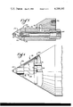
- FIG. 2 is a side view of the acid atomizing cyclone chamber
- FIG. 3 is an end view of the acid atomizing cyclone chamber
- FIG. 4 is a top view of the acid atomizing cyclone chamber
- FIG. 5 is an axial cross-section of an atomizing injection nozzle
- FIG. 6 is a side view partially broken away and partly in section, of an injection nozzle mounted in a nozzle holder.
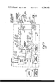
- FIG. 7 is a schematic flow diagram of a typical type of gas conditioning apparatus.
- the improved gas conditioning apparatus shown generally at 10 includes an acid day tank 12 and an air tank 14.
- Acid lines 16 and an air line 18 are connected to a plurality of atomizing chamber assemblies (only one being shown) indicated generally at 20 which have acid mist injection nozzles 22 extending thereinto and acid vapor injection lances 24 extending therefrom.
- the lances 24 are adapted to pass through the top of a duct member 26 at a position in a flue gas stream which is upstream from an electrostatic precipitator (not shown).
- the particular position upstream should be such that the acid vapor will be uniformly dispersed by the time it reaches the precipitator and the number and position of the lances should be selected to provide uniform dispersion.
- Hot gases preferably from a combustion air preheater (not shown) are introduced into the chamber 20 through inlet pipe 28 (FIGS. 1-4).
- the gases travel in a helical or cyclonic fashion from one end of the chamber to the other where they exit through lance 24 and are distributed through openings 30 into the flue gas stream in the duct 26.
- the nozzle 22 is mounted at the tip of the nozzle holder 32 at a point on the axis of the chamber 20 which is preferably about 2" downstream of the inlet pipe 28.
- a clamp 34 carried by the nozzle holder 32 engages the air and acid lines 18 and 16 to maintain the nozzle position fixed relative to the nozzle holder.
- a flange 35 welded to the nozzle holder 32 affixes the nozzle holder to the chamber 20.
- the nozzle member 22 is shown in detail in FIG. 5.
- the nozzle includes a main body portion 36 preferably formed of tantalum and having positioned within it an orifice member 38 containing an orifice 40 and including an inlet cone portion 42 and an outlet cone portion 44.
- the orifice 40 acts as a venturi to increase the velocity of the air drawn in through threaded opening 45 by which the nozzle is attached to air line 18 and to assist in drawing liquid acid through two pairs of opposed holes 46 which communicate with the annular acid-containing reservoir 48 defined by the orifice member 38 and the body 36 and by the acid inlet opening 50 which communicates with an opening 52 attached to acid line 16.
- nozzle 22 Positioned at the outer end of the nozzle 22 are a pair of support arms 54 which carry and support a resonator cup member 56 having a cavity 58.
- the nozzle 22 produces an intense field of sonic energy which breaks the acid particles up into an extremely fine mist having an average particle size of about 10 microns.
- the model is preferably made in a shape similar to the Model 052 nozzle sold by Sonic Development Corporation of Upper Saddle River, New Jersey. The theory of operation of such nozzles is generally explained in U.S. Pat. No. 3,240,254, which patent is incorporated by reference herein.
- the nozzle 22 is preferably made of tantalum or other material capable of withstanding the corrosive environment produced by the liquid acid within the nozzle and the hot acid mist or vapor which can contact the exterior portions of the nozzle.
- Materials such as stainless steel and Hastelloy normally offered by the nozzle manufacturer for corrosion resistance are of little use in a hot acid environment since they would corrode very quickly.
- FIG. 6 illustrates the manner in which the nozzle 22 is mounted in the nozzle holder 32.
- the nozzle holder includes a machined nose portion 59 which is welded to a formed sheet metal portion 60.
- An O-ring seal 61 located in a groove in the nose portion supports the forward portion of the nozzle 22 while the rearward portion is supported by the clamp 34 (FIG. 1) which contacts pipes 16 and 18.
- the nose cone portion 59 preferably has an included angle of about 60° and is flush and aligned with the nozzle 22 as shown in the drawing.
- the system for supplying acid to the nozzles 22 includes a day tank 12 having a sight gauge 62 (FIG. 1) and high and low level alarm systems connected to indicators and a horn (not shown).
- a plurality of metering pumps 64 are controled by switches 66, with each pump capable of supplying acid to two acid lines 16.
- control panel 68 preferably includes acid flow indicators 70, a tank liquid level indicator, a tank temperature indicator, a system "on” indicator, a power “on” indicator and pressure gauges for inlet acid, inlet air, outlet acid and outlet air.
- a temperature set point gauge 71 is also provided for setting the lowest temperature of the flue gases at which the system will operate. This keeps the system from operating below the dew point of the acid. Most of the aforementioned instruments are omitted from FIG. 1 for clarity but are described infra in connection with FIG. 7.
- FIG. 7 illustrates a schematic flow diagram of a gas conditioning system incorporating the invention which might be typically used in a commercial situation.
- the system illustrated in FIG. 7 utilizes a plurality of metering pumps 64 which are positive displacement pumps.
- the number of pumps used depends on the total flow required with a different pump being used for each single chamber 20 or a pair of chambers.
- the pumps pull in a given quantity of acid from the day tank 12 on the suction stroke and force it through the outlet on the pressure stroke.
- the quantity of acid delivered to and by each pump is determined by pneumatic output valves 72 which are operated by the load signal 74 in response to a parameter such as the volume of flue gases or the amount of SO 3 in the flue gases downstream of the precipitator.
- the downstream piping resistance to flow does not materially effect the flow output of the metering pumps.
- the acid day tank 12 includes high and low level alarms 76 and a level indicator 78.
- the acid is piped from the day tank 12 to the metering pump or pumps 64. As previously mentioned, the number of pumps 64 depends on the total flow required.
- the acid is piped from the pumps 64 through a pulsation dampener 80 which serves to smooth out the flow due to the piston strokes of the pump.
- the line 82 between the pulsation dampener 80 and the nozzles 22 includes a pressure gauge 84 for measuring the pressure, a pressure switch 86 which serves as an alarm for abnormal pressure conditions, a backpressure valve 88 which produces the pressure needed for the pump check valves (not shown) to close tightly, a flow indicator 70 to indicate that the pump is actually pumping and a shut-off valve 92 to close off the acid line.
- Air dryers 94 are provided for cleaning and drying the incoming air before it passes to an air receiving tank 14 which holds a supply for limited times when the supply 96 may fail. After the air leaves tank 14 it passes through a flow indicator 98 and then through a pressure regulator 100 and a pressure gauge 102 before passing through lines 104 which are connected to the nozzles 22.
- a purge line 106 containing a one way valve 108 and a flow control valve 110 is connected between the air tank 14 and the acid line 112 exiting the tank 12 so that the acid in the acid lines can be forced out when desired.
- the optimum acid injection rate for the gas conditioning apparatus is the one that produces the best results in fly ash collection without acid carrying over past the precipitator. This rate is generally between 15-30 ppm acid to flue gas. The exact ratio will vary, however, with the flue gas rate, the coal analysis, plant operation, precipitator condition, and other variables.
- One method of determining and controlling the acid injection rate is as follows. For a given coal the plant is operated at full rate and the acid injection through nozzles 22 is increased to the point of maximum precipitator collection efficiency as determined by observing the stack, observing the precipitator electrical performance parameters and/or taking flue gas samples. After the correct rate for the plant at full load is known, a signal 74 provided to the conditioning unit by the plant which is roughly proportional to the flue gas flow rate should provide automatic injection of the correct amount of acid. This signal is transmitted to the control valve 72 and permits the acid injection rate to drop proportionally to any drop in the flue gas flow rate. Thus, the amount of acid being injected can be kept in constant proportion to the flue gas.
- a temperature set gauge 71 is provided to shut off the injection of acid if the flue gas temperature should get so low that the dew point of the acid might be reached.
- dew points typically range from 250° to 285° F. the set point is generally set at 285°-300° F. to provide a safety factor.
- the typical flue gas temperature would be 330° to 430° F.
- the air pressure value is at least about 10 psig above the fluid value. If the air pressure value is too high the spray pattern will be very wide and may angle back sufficiently about the nozzle to form droplets, defeating the purpose of the nozzle. If the air pressure is too high, it is also possible to cut off the flow of acid from the nozzle. If the air pressure is too low, no atomization will occur and the acid will dribble from the nozzle.
- the orifice opening 40 had a diameter of 0.053 inches while the holes 46 through which the acid passes had a diameter of 0.029 inches.
- a typical operating pressure for a nozzle might be 2.5 gph flow and 4 psig pressure for the acid and 2.5 SCFM flow and 38 psig pressure for the air. These pressures would be measured at pressure gauges 84, 102.
Landscapes
- Chemical & Material Sciences (AREA)
- Chemical Kinetics & Catalysis (AREA)
- Electrostatic Separation (AREA)
- Treating Waste Gases (AREA)
Priority Applications (9)
| Application Number | Priority Date | Filing Date | Title |
|---|---|---|---|
| US05/955,554 US4208192A (en) | 1978-10-27 | 1978-10-27 | Sonic spray of H2 SD4 in a swirling heated air stream |
| IN720/DEL/79A IN153232B (fr) | 1978-10-27 | 1979-10-15 | |
| ES485318A ES8100110A1 (es) | 1978-10-27 | 1979-10-24 | Metodo de inyectar un agente de acondicionamiento acido en una corriente de gases residuales que contiene cenizas volantes |
| CA338,471A CA1132063A (fr) | 1978-10-27 | 1979-10-25 | Methode et dispositif de traitement des gaz de carneau avec un brouillard de h.sub.2so.sub.4 |
| GB7937284A GB2035830B (en) | 1978-10-27 | 1979-10-26 | Conditioning flue gas with a vaporized mist of h2 so4 |
| JP13858979A JPS5570357A (en) | 1978-10-27 | 1979-10-26 | Method of injecting acid conditioning agent to flue gas flow and its device |
| DE19792943349 DE2943349A1 (de) | 1978-10-27 | 1979-10-26 | Verfahren und vorrichtung zum einspritzen eines saeure-konditioniermittels in einen rauchgasstrom |
| IT26850/79A IT1124693B (it) | 1978-10-27 | 1979-10-26 | Procedimento e apparecchiatura per il condizionamento di un gas combusto con una nebbia vaporizzata di acido solforico |
| ES489016A ES489016A0 (es) | 1978-10-27 | 1980-02-28 | Aparato para inyectar un vapor de acido liquido a una corriente de gas de chimenea |
Applications Claiming Priority (1)
| Application Number | Priority Date | Filing Date | Title |
|---|---|---|---|
| US05/955,554 US4208192A (en) | 1978-10-27 | 1978-10-27 | Sonic spray of H2 SD4 in a swirling heated air stream |
Publications (1)
| Publication Number | Publication Date |
|---|---|
| US4208192A true US4208192A (en) | 1980-06-17 |
Family
ID=25496989
Family Applications (1)
| Application Number | Title | Priority Date | Filing Date |
|---|---|---|---|
| US05/955,554 Expired - Lifetime US4208192A (en) | 1978-10-27 | 1978-10-27 | Sonic spray of H2 SD4 in a swirling heated air stream |
Country Status (8)
| Country | Link |
|---|---|
| US (1) | US4208192A (fr) |
| JP (1) | JPS5570357A (fr) |
| CA (1) | CA1132063A (fr) |
| DE (1) | DE2943349A1 (fr) |
| ES (2) | ES8100110A1 (fr) |
| GB (1) | GB2035830B (fr) |
| IN (1) | IN153232B (fr) |
| IT (1) | IT1124693B (fr) |
Cited By (26)
| Publication number | Priority date | Publication date | Assignee | Title |
|---|---|---|---|---|
| US4466815A (en) * | 1982-05-03 | 1984-08-21 | Wahlco International Inc. | Gas conditioning apparatus |
| US4579726A (en) * | 1981-04-15 | 1986-04-01 | Outokumou Oy | Process and apparatus for the removal of mercury from sulfur dioxide-bearing hot and moist gases |
| US4738690A (en) * | 1985-03-29 | 1988-04-19 | Gus, Inc. | Method of removing entrained particles from flue gas and composition of matter |
| US4770674A (en) * | 1984-08-06 | 1988-09-13 | Foster Wheeler Energy Corporation | Gas conditioning for an electrostatic precipitator |
| US5074226A (en) * | 1991-02-15 | 1991-12-24 | Field Service Associates, Inc. | Flue gas conditioning system |
| US5196038A (en) * | 1990-03-15 | 1993-03-23 | Wright Robert A | Flue gas conditioning system |
| US5240470A (en) * | 1992-04-07 | 1993-08-31 | Wilhelm Environmental Technologies, Inc. | In-duct flue gas conditioning system |
| US5261931A (en) * | 1990-03-15 | 1993-11-16 | Wilhelm Environmental Technologies, Inc. | Flue gas conditioning system |
| US5288309A (en) * | 1992-04-07 | 1994-02-22 | Wilhelm Environmental Technologies, Inc. | Flue gas conditioning agent demand control apparatus |
| US5350441A (en) * | 1990-03-15 | 1994-09-27 | Wilhelm Environmental Technologies, Inc. | Flue gas conditioning system |
| US5356597A (en) * | 1992-04-07 | 1994-10-18 | Wilhelm Environmental Technologies, Inc. | In-duct flue gas conditioning system |
| US5370720A (en) * | 1993-07-23 | 1994-12-06 | Welhelm Environmental Technologies, Inc. | Flue gas conditioning system |
| US5449390A (en) * | 1994-03-08 | 1995-09-12 | Wilhelm Environmental Technologies, Inc. | Flue gas conditioning system using vaporized sulfuric acid |
| US5591253A (en) * | 1995-03-07 | 1997-01-07 | Electric Power Research Institute, Inc. | Electrostatically enhanced separator (EES) |
| US5681375A (en) * | 1996-07-16 | 1997-10-28 | Wilhelm Environmental Technologies, Inc. | Boiler flue gas conditioning system using dilute sulfuric acid injection |
| US20040195379A1 (en) * | 2003-03-11 | 2004-10-07 | Trent Rance | Spray nozzle suitable for use in hot corrosive environments and method of use |
| US6964698B1 (en) * | 2004-06-07 | 2005-11-15 | Balcke-Durr Gmbh | Gas supply for electrostatic filter and electrostatic filter arrangement |
| US7156902B1 (en) * | 2005-05-04 | 2007-01-02 | Electric Power Research Institute | Wet electro-core gas particulate separator |
| US20070041885A1 (en) * | 2005-08-18 | 2007-02-22 | Maziuk John Jr | Method of removing sulfur dioxide from a flue gas stream |
| US20070081936A1 (en) * | 2005-09-15 | 2007-04-12 | Maziuk John Jr | Method of removing sulfur trioxide from a flue gas stream |
| US20100043634A1 (en) * | 2008-08-25 | 2010-02-25 | Eisenmann Corporation | Method and apparatus for eliminating or reducing waste effluent from a wet electrostatic precipitator |
| US8178145B1 (en) | 2007-11-14 | 2012-05-15 | JMC Enterprises, Inc. | Methods and systems for applying sprout inhibitors and/or other substances to harvested potatoes and/or other vegetables in storage facilities |
| US9605890B2 (en) | 2010-06-30 | 2017-03-28 | Jmc Ventilation/Refrigeration, Llc | Reverse cycle defrost method and apparatus |
| US10076129B1 (en) | 2016-07-15 | 2018-09-18 | JMC Enterprises, Inc. | Systems and methods for inhibiting spoilage of stored crops |
| CN111874872A (zh) * | 2019-05-03 | 2020-11-03 | 托普索公司 | 用于生产硫和硫酸的方法和工艺设备 |
| RU2822142C2 (ru) * | 2019-05-03 | 2024-07-02 | Хальдор Топсёэ А/С | Способ получения серы и серной кислоты |
Citations (8)
| Publication number | Priority date | Publication date | Assignee | Title |
|---|---|---|---|---|
| US1441713A (en) * | 1921-06-03 | 1923-01-09 | Herman A Prosser | Method of conditioning gases |
| GB429604A (en) * | 1933-12-01 | 1935-06-04 | John Eliza O Breen | Improvements in steam desuperheaters |
| DE1014789B (de) * | 1954-05-11 | 1957-08-29 | Franz Magyar Dr | Vorrichtung zur Foerderung und Zerstaeubung von Fluessigkeiten, insbesondere von fluessigen Brennstoffen |
| US3704569A (en) * | 1970-04-02 | 1972-12-05 | Universal Oil Prod Co | System for conditioning flue gas with h{11 {11 so{11 |
| US3724180A (en) * | 1971-01-22 | 1973-04-03 | Environmental Ind Inc | Steam humidifier with centrifugal separator |
| US3860401A (en) * | 1973-03-06 | 1975-01-14 | Airwick Ind | Method and device for producing dry vapor |
| US4058372A (en) * | 1976-06-22 | 1977-11-15 | Air Products And Chemicals, Inc. | Flue gas conditioning with spiking gas containing sulfur trioxide |
| US4070424A (en) * | 1976-09-21 | 1978-01-24 | Uop Inc. | Method and apparatus for conditioning flue gas with a mist of H2 SO4 |
Family Cites Families (1)
| Publication number | Priority date | Publication date | Assignee | Title |
|---|---|---|---|---|
| JPS5621538B2 (fr) * | 1973-06-07 | 1981-05-20 |
-
1978
- 1978-10-27 US US05/955,554 patent/US4208192A/en not_active Expired - Lifetime
-
1979
- 1979-10-15 IN IN720/DEL/79A patent/IN153232B/en unknown
- 1979-10-24 ES ES485318A patent/ES8100110A1/es not_active Expired
- 1979-10-25 CA CA338,471A patent/CA1132063A/fr not_active Expired
- 1979-10-26 IT IT26850/79A patent/IT1124693B/it active
- 1979-10-26 JP JP13858979A patent/JPS5570357A/ja active Granted
- 1979-10-26 DE DE19792943349 patent/DE2943349A1/de not_active Withdrawn
- 1979-10-26 GB GB7937284A patent/GB2035830B/en not_active Expired
-
1980
- 1980-02-28 ES ES489016A patent/ES489016A0/es active Granted
Patent Citations (8)
| Publication number | Priority date | Publication date | Assignee | Title |
|---|---|---|---|---|
| US1441713A (en) * | 1921-06-03 | 1923-01-09 | Herman A Prosser | Method of conditioning gases |
| GB429604A (en) * | 1933-12-01 | 1935-06-04 | John Eliza O Breen | Improvements in steam desuperheaters |
| DE1014789B (de) * | 1954-05-11 | 1957-08-29 | Franz Magyar Dr | Vorrichtung zur Foerderung und Zerstaeubung von Fluessigkeiten, insbesondere von fluessigen Brennstoffen |
| US3704569A (en) * | 1970-04-02 | 1972-12-05 | Universal Oil Prod Co | System for conditioning flue gas with h{11 {11 so{11 |
| US3724180A (en) * | 1971-01-22 | 1973-04-03 | Environmental Ind Inc | Steam humidifier with centrifugal separator |
| US3860401A (en) * | 1973-03-06 | 1975-01-14 | Airwick Ind | Method and device for producing dry vapor |
| US4058372A (en) * | 1976-06-22 | 1977-11-15 | Air Products And Chemicals, Inc. | Flue gas conditioning with spiking gas containing sulfur trioxide |
| US4070424A (en) * | 1976-09-21 | 1978-01-24 | Uop Inc. | Method and apparatus for conditioning flue gas with a mist of H2 SO4 |
Cited By (52)
| Publication number | Priority date | Publication date | Assignee | Title |
|---|---|---|---|---|
| US4579726A (en) * | 1981-04-15 | 1986-04-01 | Outokumou Oy | Process and apparatus for the removal of mercury from sulfur dioxide-bearing hot and moist gases |
| US4466815A (en) * | 1982-05-03 | 1984-08-21 | Wahlco International Inc. | Gas conditioning apparatus |
| US4770674A (en) * | 1984-08-06 | 1988-09-13 | Foster Wheeler Energy Corporation | Gas conditioning for an electrostatic precipitator |
| US4738690A (en) * | 1985-03-29 | 1988-04-19 | Gus, Inc. | Method of removing entrained particles from flue gas and composition of matter |
| US5350441A (en) * | 1990-03-15 | 1994-09-27 | Wilhelm Environmental Technologies, Inc. | Flue gas conditioning system |
| US5196038A (en) * | 1990-03-15 | 1993-03-23 | Wright Robert A | Flue gas conditioning system |
| US5261931A (en) * | 1990-03-15 | 1993-11-16 | Wilhelm Environmental Technologies, Inc. | Flue gas conditioning system |
| US5074226A (en) * | 1991-02-15 | 1991-12-24 | Field Service Associates, Inc. | Flue gas conditioning system |
| US5240470A (en) * | 1992-04-07 | 1993-08-31 | Wilhelm Environmental Technologies, Inc. | In-duct flue gas conditioning system |
| US5288303A (en) * | 1992-04-07 | 1994-02-22 | Wilhelm Environmental Technologies, Inc. | Flue gas conditioning system |
| US5288309A (en) * | 1992-04-07 | 1994-02-22 | Wilhelm Environmental Technologies, Inc. | Flue gas conditioning agent demand control apparatus |
| US5356597A (en) * | 1992-04-07 | 1994-10-18 | Wilhelm Environmental Technologies, Inc. | In-duct flue gas conditioning system |
| US5547495A (en) * | 1992-04-07 | 1996-08-20 | Wilhelm Environmental Technologies, Inc. | Flue gas conditioning system |
| US5370720A (en) * | 1993-07-23 | 1994-12-06 | Welhelm Environmental Technologies, Inc. | Flue gas conditioning system |
| US5449390A (en) * | 1994-03-08 | 1995-09-12 | Wilhelm Environmental Technologies, Inc. | Flue gas conditioning system using vaporized sulfuric acid |
| US5591253A (en) * | 1995-03-07 | 1997-01-07 | Electric Power Research Institute, Inc. | Electrostatically enhanced separator (EES) |
| US5683494A (en) * | 1995-03-07 | 1997-11-04 | Electric Power Research Institute, Inc. | Electrostatically enhanced separator (EES) |
| US5681375A (en) * | 1996-07-16 | 1997-10-28 | Wilhelm Environmental Technologies, Inc. | Boiler flue gas conditioning system using dilute sulfuric acid injection |
| US20040195379A1 (en) * | 2003-03-11 | 2004-10-07 | Trent Rance | Spray nozzle suitable for use in hot corrosive environments and method of use |
| US6942168B2 (en) | 2003-03-11 | 2005-09-13 | Wafertech, Llc | Spray nozzle suitable for use in hot corrosive environments and method of use |
| US6964698B1 (en) * | 2004-06-07 | 2005-11-15 | Balcke-Durr Gmbh | Gas supply for electrostatic filter and electrostatic filter arrangement |
| US20050268784A1 (en) * | 2004-06-07 | 2005-12-08 | Thomas Davis | Gas supply for electrostatic filter and electrostatic filter arrangement |
| AU2005202330B2 (en) * | 2004-06-07 | 2009-12-03 | Howden Rothemühle GmbH. | Gas supply for electrostatic filters and electrostatic filter arrangement |
| US7156902B1 (en) * | 2005-05-04 | 2007-01-02 | Electric Power Research Institute | Wet electro-core gas particulate separator |
| US20090241774A1 (en) * | 2005-08-18 | 2009-10-01 | Solvay Chemicals | Method of Removing Sulfur Dioxide From A Flue Gas Stream |
| US7531154B2 (en) | 2005-08-18 | 2009-05-12 | Solvay Chemicals | Method of removing sulfur dioxide from a flue gas stream |
| US20070041885A1 (en) * | 2005-08-18 | 2007-02-22 | Maziuk John Jr | Method of removing sulfur dioxide from a flue gas stream |
| US7854911B2 (en) | 2005-08-18 | 2010-12-21 | Solvay Chemicals, Inc. | Method of removing sulfur dioxide from a flue gas stream |
| US7481987B2 (en) | 2005-09-15 | 2009-01-27 | Solvay Chemicals | Method of removing sulfur trioxide from a flue gas stream |
| US20070081936A1 (en) * | 2005-09-15 | 2007-04-12 | Maziuk John Jr | Method of removing sulfur trioxide from a flue gas stream |
| US8178145B1 (en) | 2007-11-14 | 2012-05-15 | JMC Enterprises, Inc. | Methods and systems for applying sprout inhibitors and/or other substances to harvested potatoes and/or other vegetables in storage facilities |
| US20100043634A1 (en) * | 2008-08-25 | 2010-02-25 | Eisenmann Corporation | Method and apparatus for eliminating or reducing waste effluent from a wet electrostatic precipitator |
| US8092578B2 (en) * | 2008-08-25 | 2012-01-10 | Eisenmann Corporation | Method and apparatus for eliminating or reducing waste effluent from a wet electrostatic precipitator |
| US20120198996A1 (en) * | 2008-08-25 | 2012-08-09 | Eisenmann Corporation | Method and apparatus for eliminating or reducing waste effluent from a wet electrostatic precipitator |
| US8591629B2 (en) * | 2008-08-25 | 2013-11-26 | Joseph Shulfer | Method and apparatus for eliminating or reducing waste effluent from a wet electrostatic precipitator |
| US8728204B2 (en) * | 2008-08-25 | 2014-05-20 | Eisenmann Corporation | Method and apparatus for eliminating or reducing quench water for a wet electrostatic precipitator |
| US8728203B2 (en) * | 2008-08-25 | 2014-05-20 | Eisenmann Corporation | Method and apparatus for eliminating or reducing quench water for a wet electrostatic precipitator |
| US9605890B2 (en) | 2010-06-30 | 2017-03-28 | Jmc Ventilation/Refrigeration, Llc | Reverse cycle defrost method and apparatus |
| US11399555B1 (en) | 2016-07-15 | 2022-08-02 | JMC Enterprises, Inc. | Systems and methods for inhibiting spoilage of stored crops |
| US10638780B1 (en) | 2016-07-15 | 2020-05-05 | JMC Enterprises, Inc. | Systems and methods for inhibiting spoilage of stored crops |
| US10653170B1 (en) | 2016-07-15 | 2020-05-19 | JMC Enterprises, Inc. | Systems and methods for inhibiting spoilage of stored crops |
| US12178229B1 (en) | 2016-07-15 | 2024-12-31 | JMC Enterprises, Inc. | Systems and methods for inhibiting spoilage of stored crops |
| US10076129B1 (en) | 2016-07-15 | 2018-09-18 | JMC Enterprises, Inc. | Systems and methods for inhibiting spoilage of stored crops |
| US11618677B2 (en) | 2019-05-03 | 2023-04-04 | Haldor Topsøe A/S | Revamping of a claus plant with a sulfuric acid plan |
| WO2020225060A1 (fr) * | 2019-05-03 | 2020-11-12 | Haldor Topsøe A/S | Procédé de production de soufre et d'acide sulfurique |
| US11691877B2 (en) | 2019-05-03 | 2023-07-04 | Haldor Topsøe A/S | Method for production of sulfur and sulfuric acid |
| US11807527B2 (en) | 2019-05-03 | 2023-11-07 | Haldor Topsøe A/S | Method for production of elemental sulfur by part or fully catalytic oxidation of Claus tail gas |
| RU2822142C2 (ru) * | 2019-05-03 | 2024-07-02 | Хальдор Топсёэ А/С | Способ получения серы и серной кислоты |
| CN111874872B (zh) * | 2019-05-03 | 2024-07-30 | 托普索公司 | 用于生产硫和硫酸的方法和工艺设备 |
| CN111874872A (zh) * | 2019-05-03 | 2020-11-03 | 托普索公司 | 用于生产硫和硫酸的方法和工艺设备 |
| US12545580B2 (en) | 2019-05-03 | 2026-02-10 | Haldor Topsøe A/S | Method for production of elemental sulfur and sulfuric acid |
| TWI918602B (zh) | 2019-05-03 | 2026-03-21 | 丹麥商托普索公司 | 製造硫和硫酸的方法 |
Also Published As
| Publication number | Publication date |
|---|---|
| ES8102831A1 (es) | 1981-02-16 |
| ES489016A0 (es) | 1981-02-16 |
| GB2035830B (en) | 1983-03-23 |
| JPS5570357A (en) | 1980-05-27 |
| CA1132063A (fr) | 1982-09-21 |
| IT1124693B (it) | 1986-05-14 |
| IN153232B (fr) | 1984-06-16 |
| ES485318A0 (es) | 1980-11-01 |
| DE2943349A1 (de) | 1980-04-30 |
| GB2035830A (en) | 1980-06-25 |
| IT7926850A0 (it) | 1979-10-26 |
| JPS631103B2 (fr) | 1988-01-11 |
| ES8100110A1 (es) | 1980-11-01 |
Similar Documents
| Publication | Publication Date | Title |
|---|---|---|
| US4208192A (en) | Sonic spray of H2 SD4 in a swirling heated air stream | |
| US4070424A (en) | Method and apparatus for conditioning flue gas with a mist of H2 SO4 | |
| CA2099521C (fr) | Utilisation de l'energie calorifique des gaz de combustion pour la vaporisation d'un reducteur aqueux servant a eliminer les nox dans les gaz de combustion | |
| KR100234572B1 (ko) | 좁은 분무각을 가진 연소용 액체연료 분무기 | |
| US4272499A (en) | Process and apparatus for the removal of particulate matter and reactive or water soluble gases from carrier gases | |
| US5279646A (en) | Venturi scrubber and process | |
| US7661662B2 (en) | Wastewater evaporation system | |
| EP0744999B1 (fr) | Buse double de vaporisation | |
| US20090294074A1 (en) | Wastewater evaporation system | |
| US20020092918A1 (en) | Hot gas atomization | |
| US5074226A (en) | Flue gas conditioning system | |
| MXPA02002780A (es) | Metodos y dispositivos de atomizacion de liquidos. | |
| US5370720A (en) | Flue gas conditioning system | |
| KR0152657B1 (ko) | 익형 분무장치 | |
| US5449390A (en) | Flue gas conditioning system using vaporized sulfuric acid | |
| CN106943758A (zh) | 一种用锅炉热风将氨水同时蒸发和稀释的装置及方法 | |
| JPS61259009A (ja) | 自由火炎バ−ナ | |
| CN206660627U (zh) | 一种用锅炉热风将氨水同时蒸发和稀释的装置及系统 | |
| US5681375A (en) | Boiler flue gas conditioning system using dilute sulfuric acid injection | |
| GB1592844A (en) | Method and apparatus for conditioning flue gas with a mist of acid | |
| EP0360856B1 (fr) | Procede reduisant la concentration de polluants dans un effluent | |
| JP4382477B2 (ja) | 噴射装置並びにその使用方法 | |
| CN212396275U (zh) | 一种全负荷除尘器提效及废水蒸发系统 | |
| EP0079081A2 (fr) | Buse de pulvérisation pour réacteurs de SO2 dans des installations de nettoyage de gaz des tuyaux de poêle | |
| JPS6475026A (en) | Wet type simultaneous desulfurization-denitrification process |
Legal Events
| Date | Code | Title | Description |
|---|---|---|---|
| AS | Assignment |
Owner name: UOP, DES PLAINES, IL, A NY GENERAL PARTNERSHIP Free format text: ASSIGNMENT OF ASSIGNORS INTEREST.;ASSIGNOR:KATALISTIKS INTERNATIONAL, INC., A CORP. OF MD;REEL/FRAME:005006/0782 Effective date: 19880916 |
|
| AS | Assignment |
Owner name: UOP, A GENERAL PARTNERSHIP OF NY, ILLINOIS Free format text: ASSIGNMENT OF ASSIGNORS INTEREST.;ASSIGNOR:UOP INC.;REEL/FRAME:005077/0005 Effective date: 19880822 |