US4209196A - Sun roof for cars - Google Patents
Sun roof for cars Download PDFInfo
- Publication number
- US4209196A US4209196A US05/917,581 US91758178A US4209196A US 4209196 A US4209196 A US 4209196A US 91758178 A US91758178 A US 91758178A US 4209196 A US4209196 A US 4209196A
- Authority
- US
- United States
- Prior art keywords
- frame
- support
- roof
- opening
- sun roof
- Prior art date
- Legal status (The legal status is an assumption and is not a legal conclusion. Google has not performed a legal analysis and makes no representation as to the accuracy of the status listed.)
- Expired - Lifetime
Links
- 230000009471 action Effects 0.000 claims abstract description 15
- 230000000903 blocking effect Effects 0.000 claims abstract description 11
- 230000007246 mechanism Effects 0.000 claims abstract description 9
- 238000006073 displacement reaction Methods 0.000 claims description 6
- 230000000694 effects Effects 0.000 claims description 5
- 230000002427 irreversible effect Effects 0.000 claims description 2
- 230000008901 benefit Effects 0.000 description 3
- 230000008030 elimination Effects 0.000 description 3
- 238000003379 elimination reaction Methods 0.000 description 3
- 239000004677 Nylon Substances 0.000 description 2
- 229920001778 nylon Polymers 0.000 description 2
- 230000001131 transforming effect Effects 0.000 description 2
- 239000003795 chemical substances by application Substances 0.000 description 1
- 238000010276 construction Methods 0.000 description 1
- 230000007797 corrosion Effects 0.000 description 1
- 238000005260 corrosion Methods 0.000 description 1
- 238000010348 incorporation Methods 0.000 description 1
- 238000012423 maintenance Methods 0.000 description 1
- 239000000463 material Substances 0.000 description 1
- 239000002184 metal Substances 0.000 description 1
- 230000004048 modification Effects 0.000 description 1
- 238000012986 modification Methods 0.000 description 1
- 239000004033 plastic Substances 0.000 description 1
- 229920003023 plastic Polymers 0.000 description 1
- 239000002990 reinforced plastic Substances 0.000 description 1
- 230000007704 transition Effects 0.000 description 1
Images


Classifications
-
- B—PERFORMING OPERATIONS; TRANSPORTING
- B60—VEHICLES IN GENERAL
- B60J—WINDOWS, WINDSCREENS, NON-FIXED ROOFS, DOORS, OR SIMILAR DEVICES FOR VEHICLES; REMOVABLE EXTERNAL PROTECTIVE COVERINGS SPECIALLY ADAPTED FOR VEHICLES
- B60J7/00—Non-fixed roofs; Roofs with movable panels, e.g. rotary sunroofs
- B60J7/02—Non-fixed roofs; Roofs with movable panels, e.g. rotary sunroofs of sliding type, e.g. comprising guide shoes
- B60J7/06—Non-fixed roofs; Roofs with movable panels, e.g. rotary sunroofs of sliding type, e.g. comprising guide shoes with non-rigid element or elements
- B60J7/061—Non-fixed roofs; Roofs with movable panels, e.g. rotary sunroofs of sliding type, e.g. comprising guide shoes with non-rigid element or elements sliding and folding
-
- B—PERFORMING OPERATIONS; TRANSPORTING
- B60—VEHICLES IN GENERAL
- B60J—WINDOWS, WINDSCREENS, NON-FIXED ROOFS, DOORS, OR SIMILAR DEVICES FOR VEHICLES; REMOVABLE EXTERNAL PROTECTIVE COVERINGS SPECIALLY ADAPTED FOR VEHICLES
- B60J7/00—Non-fixed roofs; Roofs with movable panels, e.g. rotary sunroofs
- B60J7/02—Non-fixed roofs; Roofs with movable panels, e.g. rotary sunroofs of sliding type, e.g. comprising guide shoes
- B60J7/06—Non-fixed roofs; Roofs with movable panels, e.g. rotary sunroofs of sliding type, e.g. comprising guide shoes with non-rigid element or elements
Definitions
- Flexible sun roof comprise a frame designed to be displaced from front rearwards and vice versa in a rectangular opening in the roof, a flexible cover having one edge attached to the frame and the other edge, on its opposite side, fixed to the rear border of the said opening, the cover being designed to be stretched across the opening when the sun roof is in its closed position, and to be folded backwards in the open position of the sun roof, a device for moving the frame frontwards or rearwards and for applying it against the front border of the said opening and at least for blocking it in that position.
- the translatory and blocking movements are obtained by transforming distinct movements, e.g. in manually controlled sun roofs, by means of a handle which is pulled to bring the frame to its closed position and is rotated for effecting fastening and locking movements.
- An object of the invention is to provide a flexible sun roof of the above-described type in which the translatory and blocking movements of the frame are effected without transition by transforming a single movement, e.g. the motion of rotation of a drive shaft, a crank shaft, etc.
- FIG. 1 is a plan view of a first embodiment in which the cover has been removed and partially broken away
- FIGS. 2 and 3 are cross-sectional views along lines II--II and III--III of FIG. 1,
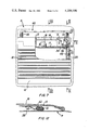
- FIG. 4 is a cross-sectional view, on an enlarged scale, taken along the section line IV--IV of FIG. 1,
- FIG. 5 is a view similar to FIG. 4 illustrating the operation of the mechanism for blocking the frame
- FIG. 6 is a plan view with parts broken away, corresponding to FIG. 4,
- FIG. 7 is a plan view of a second embodiment in which the cover and the frame are partly broken away.
- FIGS. 8 to 12 are cross-sectional views showing details and taken along the section lines VIII--VIII, IX--IX, X--X, XI--XI, and XII--XII of FIG. 7.
- the flexible sun roof shown in FIGS. 1 to 6, which is designed to cover a rectangular opening in the roof P of a car, comprises a flexible water-proof cover 10 which extends over the edges of the opening, is supported by arches 11 and is connected, on the one hand, to a fixed frame 12 covering the rear edge of the opening in the roof and, on the other hand, to a mobile frame 13.
- the mobile frame 13 is mounted on a transverse support 14 which is displaceable backward and forward to effect a translatory movement by the interposition of four pinions 15 meshing with two racks 16 fixed along the two longitudinal edges of the roof opening.
- Two pinions 15 are fixed to the ends of a shaft 17 which can be rotated by an electric motor-reduction gear unit 18 arranged in the support 14, the other two pinions being fixed to two idle shafts 19.
- the support 14 moves backwards or forwards while entraining with it the cover 10 which is thus folded or unfolded.
- the connection between the frame 13 and the support 14 comprises, on the one hand, two brackets 20 whose horizontal arms 21 are fixed to the frame 13 and, on the other hand, springs 25.
- the brackets 20 are articulated to two shafts 22 engaged in elongate openings 23 in side plates 24 welded to the body of the support 14, and the springs 25 are tensioned between strips 26 and 27 secured to the frame 13 and the support 14, respectively.
- the frame 13 and the support 14 may thus effect a relative movement in the direction of the translatory movement with amplitude equal to the length a of the openings 23 under the action or against the action of the springs 25 along the direction of displacement.
- the roof also comprises two straps 28 which extend underneath the cover 10 and are attached to the shafts 22 and the rear edge of the roof opening, respectively. These straps have a length such that they are stretched at the moment at which the support is at a distance a from the end of its stroke, the part in sight of the frame 13 reaching then the front edge of the roof opening.
- Each mechanism 37 comprises (FIGS. 4 to 6) a rocker 31 whose pivot pin 32 rotates in the side plates 24 by means of two connecting rods 33 and 34 adjustable in length and articulated, on the one hand, to the rocker 31 and, on the other hand, to two shafts 35 and 36 of the frame 13 and the arm 21 of their respective bracket 20.
- the displacement of the support 14 has the effect of causing the rockers 31 to pivot, of loading the springs 25, and of lowering and blocking the frame 13 against the edge 30.
- the drive of the motor-reduction gear 18 is irreversible, and thus, upon stopping, it locks the support 14 independently of its position, in particular its blocking position.
- Another advantage of the above described roof is that it is self-adjusting in the sense that, during assembly, it is unnecessary to take into account possible small differences in length of the straps 28 (such differences being due to construction tolerances, or other factors such as storage time length, humidity, temperature, etc.), since a margin b makes it possible to compensate for them.
- This margin makes also possible to take up elongation of the straps 28 caused by wear without negatively affecting the operation of the mechanism and the tighteness of the roof.
- incorporation of the motor 18 in the support 14 constitutes an important advantage with respect to flexible sun roofs in which the frame is caused to translate by a fixed motor by way of delicate drive means which are exposed to agents such as dusts, rain, etc. which may put them out of operation very rapidly.
- the flexible sun roof illustrated in FIGS. 7 to 12 comprises, as in the above-described embodiment, a flexible cover 10 which is attached, on the one hand, to a rear fixed frame 12 and, on the other hand, to a front frame 13 mounted on a support 14 which can be displaced backwards or forwards by means of a drive shaft 17 of a motor-reduction gear 18.
- the straps 28 (only one being shown in the drawings) are disposed laterally outside the roof opening and no longer at a given distance from the edge of this opening.
- the straps are arranged in borders formed in the longitudinal edges of the cover 10 and are fixed to two frames as described in greater detail below.
- the motor-reduction gear 18 is located at the rear zone of the support 14, the device designed to lower the frame 13 and to apply it against the front edge of the roof opening, upon closing the roof, and to detach and raise it upon opening the roof, this embodiment is similar to the previously described one. Thus, it has not been illustrated in detail in the drawings.
- the frame 40 which is inserted in the roof opening, comprises two longitudinal Z-shaped sections 41 and two transverse angled sections 42.
- the upper wings of these sections cover the four edges of the roof opening to which they are fixed by means of screws 43, nuts 44 and washers 45.
- the rear frame 12 rests on brackets 46 internally welded to the vertical wing of a respective section 42.
- the frame 12 is fixed to the brackets by means of bolts 47.
- the clamping action is such that the slightly folded over edge of the frame is resiliently applied with a certain amount of pressure against a respective edge of the roof opening to ensure perfect tighteness along this edge.
- the drive means of the support 14 comprises (FIGS. 7 and 9) two flexible notched belts 48 extending above and along the lower wings of the sections 41. These belts are fixed at their two ends to the respective sections 42, at the back by means of a tensioning device 49.
- Each device 49 comprises (FIGS. 9 and 11) a wedge 50 inserted in a square tubular body 50, a corresponding end of the belt 48 being clamped therebetween, and a screw 51 passing axially through the wedge 50 and engaging a nut 52 welded to the vertical wing of the section 42.
- the body 60 can be axially displaced but is prevented from rotating so that by screwing or unscrewing the screw 51 the belt 48 is tensioned to a larger or smaller extent.
- the belts 48 engage two respective pinions 53 keyed on a respective end of the drive shaft 17 and turn round two turn-around rollers 54 arranged on opposite sides of each oinion 53 so as to distribute the load transmitted to them to several teeth of the pinion 53.
- rollers 54 freely rotate on shafts 55 blocked in holes drilled in the bearings 56 of shaft 17.
- the support 14 When the shaft 17 is rotated by the motor 18, the support 14 is displaced forwards or backwards depending on the direction of rotation. During this movement, the support 14 is guided by two slide blocks 57 made of nylon, one on each side, the blocks 57 sliding along the lower wings of the section 41. Moreover, the blocks 57 rest and slide on two plates also consisting of nylon.
- the belts 48 consist of an optionally-reinforced plastics material having a high strength, good dimensional stability, and maximum tensile strength, because in their locking position the belts are subjected to relatively high stress.
- the straps 28 are fixed to the frames 12 and 13 by means of spring means (FIG. 12) each comprising a spring blade 60 which is riveted at one of its ends to the frame, a plastics wedge 61, and an internally conical sleeve 62. The end of the strap is wound about the wedge 61 and the sleeve 62 is force-engaged on the assembly.
- spring means FIG. 12
- the invention is not limited to the two above-described and illustrated embodiments.
- a modification can be made which consists in substituting a manual control for the motorized control, the manual control having the same cinematics but the support is caused to displace for example by a cranck and locking is obtained by a tangent-screw gear arranged between the crank and the shaft 17.
- the mechanisms designed to lower and rise the frame 13 could comprise a cable systems instead of connecting rods 33 and 34.
- connection between the frame 13 and the support 14 could be obtained by elements defining a deformable parallelogram instead of brackets 20.
- toothed belts 48 have not necessarily to pass around the rollers 54 located before and after the driving pinions 53.
- Other solutions could be devised to ensure a good distribution of the load transmitted by the pinions 53 to the support 14.
Landscapes
- Engineering & Computer Science (AREA)
- Mechanical Engineering (AREA)
- Seal Device For Vehicle (AREA)
- Body Structure For Vehicles (AREA)
- Power-Operated Mechanisms For Wings (AREA)
- Fittings On The Vehicle Exterior For Carrying Loads, And Devices For Holding Or Mounting Articles (AREA)
Applications Claiming Priority (4)
| Application Number | Priority Date | Filing Date | Title |
|---|---|---|---|
| CH781777A CH609284A5 (en) | 1977-06-22 | 1977-06-22 | Flexible sunroof for a motor vehicle |
| CH7817/77 | 1977-06-22 | ||
| CH3260/78 | 1978-03-28 | ||
| CH326078A CH621974A5 (en) | 1978-03-28 | 1978-03-28 | Flexible sunroof for a motor vehicle |
Publications (1)
| Publication Number | Publication Date |
|---|---|
| US4209196A true US4209196A (en) | 1980-06-24 |
Family
ID=25692591
Family Applications (1)
| Application Number | Title | Priority Date | Filing Date |
|---|---|---|---|
| US05/917,581 Expired - Lifetime US4209196A (en) | 1977-06-22 | 1978-06-21 | Sun roof for cars |
Country Status (6)
| Country | Link |
|---|---|
| US (1) | US4209196A (it) |
| EP (1) | EP0000320B1 (it) |
| CA (1) | CA1118814A (it) |
| DE (1) | DE2860272D1 (it) |
| ES (1) | ES471025A1 (it) |
| IT (1) | IT1096006B (it) |
Cited By (3)
| Publication number | Priority date | Publication date | Assignee | Title |
|---|---|---|---|---|
| US4422686A (en) * | 1981-12-07 | 1983-12-27 | American Sunroof Corporation | Vehicle roof structure |
| US4925238A (en) * | 1989-01-31 | 1990-05-15 | Doug Thaler | Vehicle sunroof shade |
| US20070187983A1 (en) * | 2003-12-06 | 2007-08-16 | Wilhelm Larmann Gmbh | Cabriolet vehicle with cover support strap |
Families Citing this family (1)
| Publication number | Priority date | Publication date | Assignee | Title |
|---|---|---|---|---|
| DE4042020C1 (it) * | 1990-12-28 | 1992-02-27 | Rockwell Golde Gmbh, 6000 Frankfurt, De |
Citations (4)
| Publication number | Priority date | Publication date | Assignee | Title |
|---|---|---|---|---|
| FR2263120A2 (it) * | 1972-08-24 | 1975-10-03 | Pininfarina Spa Carrozzeria | |
| US4134611A (en) * | 1976-09-16 | 1979-01-16 | Endrust Holdings Limited | Folding roof |
| US4136906A (en) * | 1976-09-02 | 1979-01-30 | Edward Rose (Birmingham) Limited | Opening roof for vehicles |
| US4143907A (en) * | 1976-09-02 | 1979-03-13 | Edward Rose (Birmingham) Limited | Roof means for vehicles |
Family Cites Families (13)
| Publication number | Priority date | Publication date | Assignee | Title |
|---|---|---|---|---|
| BE624884A (it) * | ||||
| DE668406C (de) * | 1936-02-13 | 1938-12-02 | Wilhelm Baier | Falt- und Schiebedach, insbesondere fuer Kraftfahrzeuge |
| CH201483A (de) * | 1938-04-01 | 1938-11-30 | Maurice Wenger | Schiebeverdeck an Fahrzeugen. |
| GB501078A (en) * | 1949-11-01 | 1939-02-21 | George Salmons | Improvements in or connected with folding hoods for motor and other vehicles |
| DE913739C (de) * | 1952-12-09 | 1954-06-18 | Happich Gmbh Gebr | Zurueckschiebbares Verdeck fuer Kraftfahrzeuge od. dgl. |
| BE555106A (it) * | 1956-01-19 | |||
| DE1138650B (de) * | 1956-08-09 | 1962-10-25 | H T Golde G M B H & Co K G | Verschlussspriegel fuer Faltschiebedaecher von Kraftfahrzeugen |
| DE1139398B (de) * | 1958-03-26 | 1962-11-08 | H T Golde G M B H & Co K G | Schiebedach fuer Kraftfahrzeuge, in dessen Vorderspiegel ein Antriebsaggregat angeordnet ist |
| GB989694A (en) * | 1963-04-09 | 1965-04-22 | Weathershields Ltd | Opening roof for vehicles |
| FR1404296A (fr) * | 1964-08-17 | 1965-06-25 | Golde Gmbh H T | Toit de véhicule présentant une ouverture destinée à être obstruée par un rideau pliant |
| FR1469539A (fr) * | 1965-12-28 | 1967-02-17 | Citroen Sa Andre | Toit ouvrant souple |
| FR1547501A (fr) * | 1967-07-28 | 1968-11-29 | Citroen Sa Andre | Capote semi-automatique pour véhicule automobile |
| FR2053488A5 (it) * | 1969-07-07 | 1971-04-16 | Peugeot & Renault |
-
1978
- 1978-06-20 IT IT24717/78A patent/IT1096006B/it active
- 1978-06-21 DE DE7878810004T patent/DE2860272D1/de not_active Expired
- 1978-06-21 CA CA000305952A patent/CA1118814A/en not_active Expired
- 1978-06-21 ES ES471025A patent/ES471025A1/es not_active Expired
- 1978-06-21 US US05/917,581 patent/US4209196A/en not_active Expired - Lifetime
- 1978-06-21 EP EP78810004A patent/EP0000320B1/fr not_active Expired
Patent Citations (4)
| Publication number | Priority date | Publication date | Assignee | Title |
|---|---|---|---|---|
| FR2263120A2 (it) * | 1972-08-24 | 1975-10-03 | Pininfarina Spa Carrozzeria | |
| US4136906A (en) * | 1976-09-02 | 1979-01-30 | Edward Rose (Birmingham) Limited | Opening roof for vehicles |
| US4143907A (en) * | 1976-09-02 | 1979-03-13 | Edward Rose (Birmingham) Limited | Roof means for vehicles |
| US4134611A (en) * | 1976-09-16 | 1979-01-16 | Endrust Holdings Limited | Folding roof |
Cited By (4)
| Publication number | Priority date | Publication date | Assignee | Title |
|---|---|---|---|---|
| US4422686A (en) * | 1981-12-07 | 1983-12-27 | American Sunroof Corporation | Vehicle roof structure |
| US4925238A (en) * | 1989-01-31 | 1990-05-15 | Doug Thaler | Vehicle sunroof shade |
| US20070187983A1 (en) * | 2003-12-06 | 2007-08-16 | Wilhelm Larmann Gmbh | Cabriolet vehicle with cover support strap |
| US7422266B2 (en) * | 2003-12-06 | 2008-09-09 | Wilhelm Karmann Gmbh | Cabriolet vehicle with cover support strap |
Also Published As
| Publication number | Publication date |
|---|---|
| DE2860272D1 (en) | 1981-02-05 |
| IT7824717A0 (it) | 1978-06-20 |
| EP0000320B1 (fr) | 1980-11-12 |
| IT1096006B (it) | 1985-08-17 |
| ES471025A1 (es) | 1979-02-16 |
| CA1118814A (en) | 1982-02-23 |
| EP0000320A1 (fr) | 1979-01-10 |
Similar Documents
| Publication | Publication Date | Title |
|---|---|---|
| US3658378A (en) | Folding head control devices | |
| US2939742A (en) | Foldable vehicle top | |
| US2985483A (en) | Electrically operated slidable closure | |
| US2596355A (en) | Let-down type automobile top | |
| US3591982A (en) | Window regulator | |
| US2841441A (en) | Convertible motor vehicle body having a rigid top | |
| US7134708B2 (en) | Convertible | |
| GB2279626A (en) | Mechanism for stowing a vehicle convertible roof | |
| US8167354B2 (en) | Top for a convertible | |
| US4209196A (en) | Sun roof for cars | |
| US3863979A (en) | Automobile sliding roof with canopy frame | |
| EP0713797A1 (de) | Faltverdeck für Fahrzeuge | |
| US4039222A (en) | Vehicle sun roof | |
| DE102008009440A1 (de) | Fahrzeugsitz mit einer Sitztiefenverstellung | |
| US2973991A (en) | Control device | |
| DE10203204B4 (de) | Verstellvorrichtung für ein Faltdach eines Fahrzeugs | |
| DE3222861C2 (de) | Blendschutzvorrichtung für mit einer versenkbaren Seitenscheibe ausgerüstete Fahrzeuge | |
| DE3823087A1 (de) | Fuehrungsvorrichtung fuer die fensterscheiben innerhalb des aufbaus einer automobiltuer | |
| US2947570A (en) | Motor vehicle body telescopic roof construction | |
| DE10130359A1 (de) | Dachanordnung für ein Fahrzeug, insbesondere Kraftfahrzeug | |
| DE4332938C1 (de) | Windschutz für einen mit einem zurückklappbaren Verdeck versehenen Personenkraftwagen | |
| DE10240582A1 (de) | Rolloplane als Sonnenschutz | |
| US3960403A (en) | Retractable roof closure | |
| US2796289A (en) | Adjustable sun visors for motor vehicles | |
| DE958620C (de) | Schiebedacheinrichtung fuer Fahrzeuge zur Personen- oder Lastenbefoerderung, insbesondere fuer Fahrerhaeuser von Lastkraftwagen od. dgl. |