US4214663A - Transfer apparatus for selectively transferring objects from a delivery conveyor to selected sections of a receiving conveyor - Google Patents
Transfer apparatus for selectively transferring objects from a delivery conveyor to selected sections of a receiving conveyor Download PDFInfo
- Publication number
- US4214663A US4214663A US05/814,427 US81442777A US4214663A US 4214663 A US4214663 A US 4214663A US 81442777 A US81442777 A US 81442777A US 4214663 A US4214663 A US 4214663A
- Authority
- US
- United States
- Prior art keywords
- shift register
- conveyor
- transfer
- delivery conveyor
- receiving
- Prior art date
- Legal status (The legal status is an assumption and is not a legal conclusion. Google has not performed a legal analysis and makes no representation as to the accuracy of the status listed.)
- Expired - Lifetime
Links
Images




Classifications
-
- B—PERFORMING OPERATIONS; TRANSPORTING
- B65—CONVEYING; PACKING; STORING; HANDLING THIN OR FILAMENTARY MATERIAL
- B65G—TRANSPORT OR STORAGE DEVICES, e.g. CONVEYORS FOR LOADING OR TIPPING, SHOP CONVEYOR SYSTEMS OR PNEUMATIC TUBE CONVEYORS
- B65G47/00—Article or material-handling devices associated with conveyors; Methods employing such devices
- B65G47/52—Devices for transferring articles or materials between conveyors i.e. discharging or feeding devices
- B65G47/525—Devices for transferring articles or materials between conveyors i.e. discharging or feeding devices using fluid jets
-
- B—PERFORMING OPERATIONS; TRANSPORTING
- B07—SEPARATING SOLIDS FROM SOLIDS; SORTING
- B07C—POSTAL SORTING; SORTING INDIVIDUAL ARTICLES, OR BULK MATERIAL FIT TO BE SORTED PIECE-MEAL, e.g. BY PICKING
- B07C5/00—Sorting according to a characteristic or feature of the articles or material being sorted, e.g. by control effected by devices which detect or measure such characteristic or feature; Sorting by manually actuated devices, e.g. switches
- B07C5/36—Sorting apparatus characterised by the means used for distribution
- B07C5/361—Processing or control devices therefor, e.g. escort memory
-
- B—PERFORMING OPERATIONS; TRANSPORTING
- B07—SEPARATING SOLIDS FROM SOLIDS; SORTING
- B07C—POSTAL SORTING; SORTING INDIVIDUAL ARTICLES, OR BULK MATERIAL FIT TO BE SORTED PIECE-MEAL, e.g. BY PICKING
- B07C5/00—Sorting according to a characteristic or feature of the articles or material being sorted, e.g. by control effected by devices which detect or measure such characteristic or feature; Sorting by manually actuated devices, e.g. switches
- B07C5/36—Sorting apparatus characterised by the means used for distribution
- B07C5/363—Sorting apparatus characterised by the means used for distribution by means of air
- B07C5/365—Sorting apparatus characterised by the means used for distribution by means of air using a single separation means
-
- Y—GENERAL TAGGING OF NEW TECHNOLOGICAL DEVELOPMENTS; GENERAL TAGGING OF CROSS-SECTIONAL TECHNOLOGIES SPANNING OVER SEVERAL SECTIONS OF THE IPC; TECHNICAL SUBJECTS COVERED BY FORMER USPC CROSS-REFERENCE ART COLLECTIONS [XRACs] AND DIGESTS
- Y10—TECHNICAL SUBJECTS COVERED BY FORMER USPC
- Y10S—TECHNICAL SUBJECTS COVERED BY FORMER USPC CROSS-REFERENCE ART COLLECTIONS [XRACs] AND DIGESTS
- Y10S209/00—Classifying, separating, and assorting solids
- Y10S209/922—Miscellaneous feed conveyors
Definitions
- the invention relates to the field of product handling.
- the invention relates to an apparatus for transferring individual objects from a delivery conveyor to segments or pockets in a receiving conveyor.
- the device has found particular use in the transferring of food products, such as candy bars, which are deposited on a delivery conveyor at random fashion.
- Certain candy bar wrapping equipment must be fed bars at a perdetermined spacing determined by pockets on a wrapper feed conveyor.
- the invention is particularly suited to filling the pockets on the wrapper feed conveyor with individual bars and is able to discriminate between undersized bars, oversized bars, and properly sized bars and transfer only the properly sized bars.
- 3,096,871 illustrates a controlled lateral transfer between parallel conveyors of objects by the interruption of photocells which through a control circuit operates a transfer mechanism.
- the control circuit determines when to activate the transfer mechanism by determining when the center of the object meets the center of the transfer mechanism.
- the Molins U.S. Pat. No. 3,437,189 illustrates an apparatus for handling rod shaped articles such as cigarettes and transferring them in multiple unit transfers.
- a transfer apparatus for selectively transferring objects such as food products like candy bars from a delivery conveyor to selected sections or pockets of a receiving conveyor by one or more transfer devices such as air jets is provided.
- the apparatus may be provided with decisional abilities enabling it to avoid transferring objects which are of an improper size and which are too closely spaced to other objects to be transferred effectively by the transfer devices.
- the device in its preferred form, consists of an object detection system which includes a detector for determining the passage of an object on the delivery conveyor, such as a photocell, and a device such as a belt pulse generator which detects movement of the delivery conveyor.
- the output of the photocell is fed into a first shift register having variable output connections to provide an initial delay adjustment capability.
- the clock input of the shift register is connected to the delivery conveyor pulse generator.
- the output of the shift register is fed into a multi-bit shift register within which the size and spacing of the objects are analyzed.
- the clock terminal of the shift register is likewise connected to the delivery conveyor pulse generator. Signals within this shift register represent the size and position of the objects on the delivery conveyor.
- a NOR gate is connected to two of the outputs of the shift register and to reset connections on the shift register to erase signals representing undersize objects.
- the inputs of two NAND gates are connected to a series of adjacent outputs of the shift register to provide an output signals which are fed through a NOR gate and amplifier into a counter.
- the counter is connected to the delivery conveyor pulse generator so that the counter output total represents a dimension by which an object exceeds a base value.
- a comparator having a variable setting provides an output when the base limit is exceeded by an amount representing a maximum object size desired.
- the output of the comparator is fed to a microprocessor which is connected to the shift register to erase signals corresponding to an oversize bar.
- Another circuit consisting of a NAND gate, three amplifiers, and a flip-flop is connected to three outputs of the shift register. This circuit determines the location of the rear end of an object passing through the system and determines whether a following object is within a certain distance. If the spacing is too close an output is provided to the microprocessor which through its connections to the shift register searches out and erases any information in the shift register relating to the leading object. Two ultimate outputs are provided from this shift register.
- the first is connected to a flip-flop to generate pulse representing the leading edge of an object.
- This pulse is fed into a leading edge shift register having intermediate outputs representing the position of air jets along the conveyor.
- the second output enters a similar but separate shift register and receives signals representing the full length of the object.
- the outputs into these latter two shift registers represent objects which are suitable for being transferred to the receiving conveyor.
- a device such as a proximity switch detects the sections on the receiving conveyor which are to be filled.
- the output of the proximity switch is fed into a shift register having an adjustable output connection to provide a delay adjustment.
- the shift register has its clock connected to a pulse generator which is connected to and detects movement of the receiving conveyor.
- the delayed signal from the proximity switch triggers a pulse generator which provides a window pulse of a variable length representing the size of a pocket within the section of the conveyor to be filled.
- This pulse in turn is fed into a series of shift registers which are also connected to the receiving conveyor pulse generator and which have variable output connections to provide an ability to adjust the position of the window and therefore the position of the pocket within the conveyor section.
- the output information is fed then to a shift register similar to that for the processed signals above having outputs corresponding to the position of the air jets.
- the microprocessor monitors the outputs of the three shift registers to determine when an object is in a position to be transferred by a particular air jet into one of the receiving positions on the receiving conveyor.
- the microprocessor Upon finding the desired relationship the microprocessor actuates an air jet to effect the transfer and erases the signals from the shift register representing the filled pockets and the object transferred so that a downstream jet will not turn to try to move an object that has already been transferred.
- a signal from the full length object shift register turns off the air jet so as not to affect other objects on the conveyor.
- any one or all of the oversized, undersized, or gap detection circuits may be omitted from the transfer system.
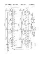
- FIG. 1 is a schematic diagram of a portion of the transfer apparatus illustrating the delivery conveyor and the inputs to the hard wired portions of the system that determine the presence of undersize bars, oversize bars, and bars that are too closely spaced.
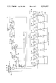
- FIG. 2 is a schematic diagram of a portion of the transfer apparatus illustrating the bar pulse shift register and a representative connection to an air jet.
- FIG. 3 is a schematic diagram of a portion of a transfer apparatus illustrating the full bar shift register.
- FIG. 4 is a schematic diagram of a portion of the transfer apparatus illustrating the receiving conveyor and the inputs to the pocket shift register.
- FIG. 5 is a block diagram of the transfer apparatus illustrating the operation of the system.
- FIG. 6 is a perspective view of the conveyors, air jets, bars, sensors, and the backstop panel illustrating the transfer of the bars.
- FIGS. 7, 8, and 9. together, form the logic flow chart for the Central Processor Unit operation, which erases information relating to oversize bars and a leading bar that is too close to a following bar, when the figures are joined at the connection points E, G and H.
- An apparatus is provided to effect the transfer of objects from the delivery conveyor, whether randomly or uniformly spaced, to pockets on a receiving conveyor which may themselves be uniformly or randomly spaced. The transfer may be conditioned on the object meeting selected size criteria as well as having a satisfactory position relative to other objects on the delivery conveyor.
- the candy bars 20 are transferred from a bulk product conveyor 22 onto a delivery conveyor 24 traveling in the direction of the arrow 26.
- the spacing of the bars 20 is random.
- the delivery conveyor 24 is moving faster than the bulk product conveyor 22 so that some spacing of the product is achieved.
- An adjacent conveyor 28 for receiving the bars 20 has receiving sections, or pockets 30 defined by separating pusher bars 32.
- the receiving conveyor, traveling in the direction of the arrow 34 delivers the bars, with no more than one per section 30, to a wrapping machine, not shown.
- the bars 20 are transferred from the delivery conveyors 24 to the receiving conveyor 28, by transfer devices such as the eight air jets 36 illustrated in FIG. 6. They are sequentially spaced along the delivery conveyor to direct a stream of air 38 across the conveyor to blow the bars into the pockets 30 when a bar is opposite a jet and an empty pocket.
- the air jets 36 contain a control valve 40 which permits selective actuation of an individual air jet. In an actual operation of the preferred embodiment, where the bars 20 were an average of 21/4" in length and the pockets ranged generally from 4 to 8" in length, an air jet spacing of approximately 2" was used and found satisfactory.
- the backstop prevents the bars from overshooting the receiving conveyor and preferably has a downtilted portion 43 to deflect the bars down into the pockets of the receiving conveyor.
- the pockets of the conveyor may be shaped with an integral bumper or the conveyor may be of a width such that the use of a backstop may be unnecessary.
- the delivery conveyor 24 delivered bars at a variable rate up to 400 bars per minute and the receiving conveyor could feed up to 200 bars per minute to the wrapper.
- the first two, or upstream air jets 36 operated on a regular basis. The alignment required usually occurred before the bars passed the second air jet.
- the apparatus may be used with one or more transfer devices and is not limited to use with eight transfer devices.
- FIG. 5 illustrates the operation of the transfer apparatus.
- Bar position information is fed into an adjustable delay 50 which accounts for the positioning of sensors in the system.
- This delay information is fed into a bar shift register 52 which stores and shifts information relating to the bar in a manner corresponding to the movement of the bars on the delivery conveyor.
- Input to the bar shift register 52 relating to the delivery conveyor position controls the speed of shifting. The information can be considered to shift in the direction of the arrow 54.
- a filter system screens out bars which are considered too large or too small so that they will not be transferred.
- An undersize bar detection system 56 monitors the bar information in the bar shift register 52 and erases the information from the bar shift register 52 relating to undersize bars.
- An adjustable oversize bar detection system 58 also monitors the information in the bar shift register 52 and generates an output when an oversize bar is found.
- An undersize spacing detection system 60 having an input from a gap size adjustment 62 likewise monitors the bar shift register 52. It provides an output signal when the space between two objects is too small. This information may be important because the transfer device such as an air jet may not work properly if the bars are too closely spaced.
- a logic system such as a central processing unit, CPU, 64 erases the information in the bar shift register 52 relating to the oversize bar or one of the bars which are too closely spaced.
- Information arriving at the far end 66 of the bar shift register 52 will contain only information relating to bars which are suitable for transfer to the receiving conveyor.
- a pulse representing the front of a bar is derived at 68 from the filtered, or processed, bar information.
- An adjustment 70 is provided.
- the pulse is placed in a bar pulse shift register 72.
- the shift register 72 has a plurality of outputs 74 having positions that correspond to the position of the air jets 36.
- a bar pulse then appears at an output when the leading edge of the corresponding bar is adjacent the corresponding air jet.
- the filtered information from the bar shift register 52 after passing through an adjustment 76, enters a full bar shift register 78.
- This register also has outputs 80 which correspond to the location of the air jets 36.
- a parallel information system processes information relating to the pockets in the receiving conveyor.
- Information on the position of a pocket, after being processed in an adjustable delay 82 is fed into a window pulse generator 84.
- the window pulse generator generates a pulse of an adjustable length which is movable by the window position adjust 86 to represent the desired range of placement of a bar in a pocket.
- the window information is deposited in a pocket shift register 88 which shifts the information in a manner corresponding to the movement of the receiving conveyor.
- the pocket shift register 88 has a plurality of outputs 90 having positions that correspond to the position of the air jets.
- the CPU is connected to and AND's the outputs of the pocket shift register 88 with the corresponding outputs of the bar pulse shift register 72.
- An AND condition will occur when an air jet, bar, and pocket are in a sufficiently aligned relationship for a transfer of the bar to be possible.
- the CPU then turns on the corresponding air jet to effectuate a transfer.
- the same signal that turns on the air jets is input at 92 and 94 on the pocket shift register 88 and bar pulse shift register 72 respectively to prevent the placement of another bar in a full pocket or the actuation of a second air jet where a bar was previously transferred.
- the outputs 80 to the full bar shift register turn the air jets off after a period of time corresponding to the length of the bar.
- control system shown in the block diagram of FIG. 5, is shown in more detail in FIGS. 1 through 4.
- FIG. 1 represents that portion of the system wherein information relating to bars is filtered to avoid the transfer of undersize or oversize bars and processed to detect and react to undersized gaps between bars.
- the undersize and/or oversize bar detection circuits may be omitted from the apparatus as may the undersize gap detection system if desired.
- a detector such as a photo detector 100, provides information on the passage of bars 20 along the delivery conveyor 24.
- the output of the photo detector 100 is adjustably delayed by connection of the data input of a multiple bit shift register 102.
- the shift register has its clock terminal connected to a detector, such as a pulse generator 104 connected to the delivery conveyor, which indicates movement of the delivery conveyor.
- the output of the shift register 102 is connected by an adjustable connection 106 to the data input of a multi-bit shift register 108 composed of a series of 4 bit shift registers, 110 through 125.
- Each shift register has its clock input tied to the pulse generator.
- Information relating to undersize bars is erased by OR'ing two outputs of the shift register 108 such as, 126 and 128 as through the NOR gate 130.
- the output of the NOR gate is connected to the reset inputs of shift registers 110 and 111.
- the resets to the shift registers are held in the reset mode.
- a bar is so small that it falls between the points represented by 128 and 126 the information relating to that bar is erased. No action will be taken on the undersized bar since it appears to be removed.
- a series of outputs such as those to shift registers 110, 111, 112, and 113 are AND'ed.
- the outputs are connected through the parallel NAND gates 132 and 134 which are OR'd through the NOR gate 136 and inverter 138.
- the output of the inverter 138 is connected to the reset of a counter 140 connected to the delivery conveyor pulse generator.
- the counter is reset and held from counting until all the outputs of the shift registers 110-113 ae filled indicating a bar of a base size is present. The value of the counter then represents the dimension by which the bar exceeds the base size.
- the pulse generator indicated every 1/8" movement of the delivery conveyor as in the example, then the base size would be 2" since there are 16 increments AND'ed.
- the output of the counter is connected to a comparator 142 which generates an output at 144 determined by the value selected on the four bit, binary switch 146.
- the comparator indicates when a bar over maximum desired size has been found. This is indicated by the counter achieving a value corresponding to the number of increments by which the maximum bar size exceeds the base size.
- the output of the comparator is fed to the CPU which responds in a manner described below to erase the information relating to the oversize bar. If desired the AND circuit could be omitted and the counter connected to a shift register output to see how many increments long a bar is from one end to the other.
- the circuit using the NAND gate 148, the flip-flop 150, and the inverters 151, 152, and 154 provide a one increment pulse at output 156 when there is a high-low-high condition on connections 158, 160, 162, respectively. This indicates that the end of a leading bar is between 158 and 160 and the leading edge of thee following bar is close enough to reach the output contacted by variable connection 162, which determines the size of the minimum allowable gap.
- the output on 156 goes to the CPU which responds in a manner described below to erase information relating to the leading bar.
- the output 164 connects to the CPU to allow the computer to detect the position of a bar.
- the flip-flop 166 and its associated inverters and amplifiers 167-170 receive signals from the delivery conveyor pulse generator to cycle the CPU after receiving an acknowledgement of response to the previous signal to cycle.
- the operation of the CPU in erasing bar information is illustrated by the flow chart in FIGS. 7, 8 and 9.
- the preferred form of central processing unit is based on an INTEL 8080 microprocessor described in more detail in the manufacturer's publication INTEL 8080 Microcomputer Systems User's Manual--September 1975, #98-153c, 1976, published by Intel Corporation, 3065 Bowers Avenue, Santa Clara, California 95051 and programmed in accordance with the flow chart illustrated herein and in a manner more fully detailed in Intel 8080 Assembly Language Programming Manual, #98-004C Rev. C, 1976, published also by the manufacturer.
- the CPU Upon receiving a signal from connection 200, shown on FIG. 1, indicating that the delivery conveyor has advanced the CPU starts through the erase logic system at 202. It first reads an error buffer which is initially at zero as are the other buffers in the system. If this is zero, as it will initially be, the error port is read. The error port holds a signal which is zero unless an oversize bar has been detected or an undersize gap has been detected and indicated on connections 144 and 156, respectively, in FIG. 1. If no error condition is present the routine is terminated until the system is incremented by another pulse from the delivery conveyor pulse generator 104 to start the routine again. If an error is found the error buffer is set to a non-zero condition and the first bar port is read. The first bar port is the eight outputs of shift registers 114 and 115. The second bar port is the eight outputs of shift registers 116 and 117, and so on; there being a total of four bar ports.
- a number indicating that the entire shift register pair 114 and 115 may be reset is placed in the pre-reset buffer. The next bar port is then read. If this is full a new number is placed in the pre-reset buffer and then bar port #3 is read. If full the pre-reset buffer is again given a new number and bar port #4 is read. If bar port #4 is also full the reset port is loaded with the binary number shown, a number which will cause the shift registers 114 through 121 to be reset. Then the pre-reset buffer is read, it will not be zero, and the bar status is read. The bar status is connected to connection 164 shown on FIG. 1.
- the bar status is not zero until the oversize bar or the leading bar which is too close has its trailing edge enter shift register 114.
- the non-zero condition causes the resets on the full shift registers to remain on, since the routine is terminated until the system is incremented again, to erase the trailing edge of a bar being erased. If the bar status is zero, as after sufficient incrementing occurs, the reset port is zeroed to remove the reset signals from the shift registers and the pre-reset buffer is zeroed. Then the final reset buffer, which deals with erasure of partially full registers and is described more fully below, is read, if this final reset buffer is not zero indicating that there was a partially full shift register the routine is terminated until incremented again. If it is zero, as it would be initially, the error buffer is zeroed and the routine is terminated until the system is incremented and another error is found.
- a wait state is a number that corresponds to the number of increments it will take to clear the "good" bar. This is done by counting the number of rotations right of the bar port reading until there is a zero in the least significant bit.
- a reading of [11 11 00 00] indicates a zero wait state because there is no prior bar present and a reading of [11 00 00 11] indicates a wait state of two. If the wait state is zero the wait buffer is zeroed as is the final reset buffer and the reset port is loaded with the number [00 00 11 11] to cause shift registers 114, 115, 116 and 117 to be reset. If the wait state is not zero the wait buffer is loaded with the wait state, the final reset buffer is loaded with the number which will, when used later, cause the partially full register pair to be reset, and the reset port is loaded to erase the registers for the ports which are full.
- the wait buffer is decreased by one to see if the register pair can be reset. If not the CPU proceeds to see whether any shift register pairs previously reset should now have their reset signals removed. If the partially full register pair can be reset then the final reset buffer is added to the reset port then subtracted to reset the partially full register pair. The final reset buffer is zeroed to indicate that the partially full register pair has been reset. The pre-reset buffer is then read to see if any full register pairs are still held on and if not the error buffer is zeroed.
- the leading bar is erased because it may impact on an attempt to transfer it with the trailing bar. This is because the bar will lose some of its forward momentum when hit with the air blast. This causes the bars to exit at a less than ninety degree angle to the direction of conveyor travel and possibly strike following bars.
- the information entering shift registers 122-125 shown in FIG. 1 relates only to bars which are to be transferred.
- the flip-flop 220 is connected by the adjustable connections 222 and 224 to outputs from these shift registers.
- the flip-flop provides an output at 226 in the form of a pulse representing the leading edge of the bar. This output is connected to the data input 228 of a multibit, bar pulse shift register 230 shown in FIG. 2.
- the clock terminals of the shift register components are connected to the delivery conveyor pulse generator.
- Outputs 232-239 from the shift register correspond to the position of the air jets 1-8 respectively.
- Eight binary controlled switches 240 permit the adjustment of the output connections 232-239 to the shift register 230.
- the selection of the shift register output positions to be monitored is controlled by a binary input signal on control connections 242.
- the control connections are coded by manual switches in the CPU.
- a second multibit shift register 244 has its data input 246 connected to connection 224 and its clock connected to the delivery conveyor pulse generator 104. This forms the full bar shift register which carries information on the bar sizes.
- the outputs 247-254 from the shift register correspond to the positions of the air jets 1-8, respectively.
- the binary controlled switches work as described above to permit adjustment of the output connections.
- a third multibit shift register 256 forms a window shift register which contains information relating to the size and location of pockets 30 on the receiving conveyor 28 which are to be filled.
- the pocket detection system preferably consists of a sensor, such as the proximity switch 258, for detecting the passage of a pocket by sensing the passage of the pusher bars 32. Limit switches or other sensors may be used equally well.
- the pocket detection system also includes a conveyor movement detector such as the pulse generator 260 connected to the conveyor. The outputs from these sensors are fed into a shift register 262 which provides an adjustable signal delay like shift register 102, in FIG. 1.
- the output of the pulse generator 260 is also fed into an octal counter 263, such as an CMOS Ic 4022, after passing through a Schmitt trigger 264 and inverter 266 to provide sharp input signals.
- the reset of the counter is connected to the output of the shift register 262.
- the counter provides a pulse at its output 268 of a length which depends on the place to which the adjustable loop connection 270 is connected. A pulse is generated for each pocket 30 that passes.
- the output of the counter 263 is passed through shift registers 270-274 to permit further delay before it enters the data input of the window shift register 256. This results in a signal entering the shift register representing a target position in the pocket, or window.
- the window's position and size determines where the bar will be placed in a pocket 30.
- the shift register 256 has outputs 275-282 which correspond to the position of the air jets 1-8 respectively.
- the CPU monitors outputs 275-282 of the window shift register and outputs 232-239 of the bar pulse shift register.
- the computer AND's these to determine when a bar 20, air jet 36, and window are aligned.
- the CPU provides a signal on connection 284 to actuate the air jet latch 286 which turns on the valve 36 for air jet #8 shown in FIG. 2.
- the same signal is attached to reset connections 288 and 290 on the bar pulse shift register 230 and window shift register 256 respectively to erase the signals corresponding to the bar transferred and the pocket filled. Similar connections are provided which correspond to the other air jets.
- the NOR gates 292 and inverters 294 are provided to effectively erase all the window information from the window shift register 256.
- the outputs 247-254 from the full bar shift register are connected through an inverter 296 to the corresponding reset of the air jet latch, as shown for air jet #8 in FIG. 2; to turn off the air jet after the bar would have passed.
Landscapes
- Engineering & Computer Science (AREA)
- Mechanical Engineering (AREA)
- Control Of Conveyors (AREA)
Priority Applications (2)
| Application Number | Priority Date | Filing Date | Title |
|---|---|---|---|
| US05/814,427 US4214663A (en) | 1977-07-11 | 1977-07-11 | Transfer apparatus for selectively transferring objects from a delivery conveyor to selected sections of a receiving conveyor |
| CA305,796A CA1093594A (fr) | 1977-07-11 | 1978-06-20 | Traduction non-disponible |
Applications Claiming Priority (1)
| Application Number | Priority Date | Filing Date | Title |
|---|---|---|---|
| US05/814,427 US4214663A (en) | 1977-07-11 | 1977-07-11 | Transfer apparatus for selectively transferring objects from a delivery conveyor to selected sections of a receiving conveyor |
Publications (1)
| Publication Number | Publication Date |
|---|---|
| US4214663A true US4214663A (en) | 1980-07-29 |
Family
ID=25215027
Family Applications (1)
| Application Number | Title | Priority Date | Filing Date |
|---|---|---|---|
| US05/814,427 Expired - Lifetime US4214663A (en) | 1977-07-11 | 1977-07-11 | Transfer apparatus for selectively transferring objects from a delivery conveyor to selected sections of a receiving conveyor |
Country Status (2)
| Country | Link |
|---|---|
| US (1) | US4214663A (fr) |
| CA (1) | CA1093594A (fr) |
Cited By (41)
| Publication number | Priority date | Publication date | Assignee | Title |
|---|---|---|---|---|
| FR2505231A1 (fr) * | 1981-05-09 | 1982-11-12 | Hajime Industries | Systeme de rejet de produits defectueux |
| US4406230A (en) * | 1979-02-27 | 1983-09-27 | Villemaud Jean E | Automatic conveyor system |
| US4672553A (en) * | 1983-02-03 | 1987-06-09 | Goody Products, Inc. | Order processing method and apparatus |
| US4758778A (en) * | 1985-01-02 | 1988-07-19 | Rafagnataekni (Electronics) | Method and an apparatus for determining the degree of freshness of pieces of food |
| US4773524A (en) * | 1986-03-12 | 1988-09-27 | Cambridge Consultants (Systems Engineering) Limited | Transfer arrangement |
| USRE33357E (en) * | 1983-05-27 | 1990-09-25 | Key Technology, Inc. | Optical inspection apparatus for moving articles |
| US5018073A (en) * | 1989-03-21 | 1991-05-21 | Goody Products, Inc. | High density loaded sorting conveyors |
| US5048665A (en) * | 1989-01-12 | 1991-09-17 | Dexion (Australia) Pty. Limited | Diverter mechanism |
| US5131523A (en) * | 1991-05-06 | 1992-07-21 | Fmc Corporation | Slide transfer |
| US5141094A (en) * | 1991-01-22 | 1992-08-25 | White Conveyors, Inc. | Apparatus for unloading articles |
| US5165515A (en) * | 1991-03-29 | 1992-11-24 | Rapistan Demag Corporation | Segmented pusher control for conveying system |
| US5165520A (en) * | 1990-09-04 | 1992-11-24 | La Poste | Device for controlling and regularizing the spacing objects such as parcels, packages |
| US5193685A (en) * | 1991-06-20 | 1993-03-16 | Trevithick William J | Gemstone sorting apparatus and methods |
| US5322152A (en) * | 1990-07-06 | 1994-06-21 | Halton Oy | Method and apparatus for sorting returnables |
| US5351803A (en) * | 1993-04-15 | 1994-10-04 | White Conveyors, Inc. | Apparatus and method for retrieving articles |
| US5405016A (en) * | 1992-12-08 | 1995-04-11 | Rwe Entsorgung Aktiengesellschaft | Method to separate objects of an object mixture and facility to implement such a method |
| US5603199A (en) * | 1994-05-03 | 1997-02-18 | Pvt Piepenbrock Verpackungstechnik Gmbh | System for feeding and distributing articles |
| US5657851A (en) * | 1995-07-19 | 1997-08-19 | White Conveyors, Inc. | Powered storage rail for transporting articles |
| US5660261A (en) * | 1995-07-19 | 1997-08-26 | White Conveyors, Inc. | Single latch loader and method for loading |
| US5687850A (en) * | 1995-07-19 | 1997-11-18 | White Conveyors, Inc. | Conveyor system with a computer controlled first sort conveyor |
| US5897677A (en) * | 1997-07-24 | 1999-04-27 | Owens-Brockway Glass Contianer Inc. | Sampling of hot glassware in a glassware manufacturing system |
| US5896999A (en) * | 1996-10-16 | 1999-04-27 | United Parcel Service Of America, Inc. | Sorting system |
| US5927465A (en) * | 1996-10-08 | 1999-07-27 | Mannesmann Dematic Rapistan Corp. | Conveyor sortation system with parallel divert |
| EP0982249A1 (fr) * | 1998-08-24 | 2000-03-01 | General Motors Corporation | Contrôle et appareil pour la prévention de l'accumulation des objets transportés entre des stations en série de traitement |
| US6145650A (en) * | 1999-01-29 | 2000-11-14 | Graham Packaging Company L.P. | Apparatus and method for transferring blow-molded containers to a trimmer |
| US6202825B1 (en) * | 1997-12-17 | 2001-03-20 | Vanderlande Industries Nederland B.V. | Conveyor |
| US6359247B1 (en) * | 1999-07-06 | 2002-03-19 | Quantum Conveyor Systems, Llc | Multi-fire and variable fire diverter conveyor system and method |
| EP1199264A1 (fr) * | 2000-10-17 | 2002-04-24 | G.D Societa' per Azioni | Unité de rejet de produits |
| US6513642B1 (en) | 2000-06-29 | 2003-02-04 | Rapistan Systems Advertising Corp. | Conveyor system with diverting track network |
| FR2869889A1 (fr) * | 2004-05-07 | 2005-11-11 | Materiel Arboriculture | Dispositif ejecteur pneumatique pour ligne de convoyage de produits tels que des fruits |
| US20050269185A1 (en) * | 2004-06-04 | 2005-12-08 | Roll Eric A | High speed diverter |
| US7080962B1 (en) | 2005-05-31 | 2006-07-25 | Kimberly-Clark Worldwide, Inc. | Air conveyance apparatus |
| CN1317085C (zh) * | 2003-11-20 | 2007-05-23 | 中国农业大学 | 带有气动分级机构的水果输送装置 |
| FR2902093A1 (fr) * | 2006-06-13 | 2007-12-14 | Sarl Ets Leopold Prono Sarl | Distributeur automatique pour tapis cadenceur |
| US20090272624A1 (en) * | 2008-04-30 | 2009-11-05 | Blesco, Inc. | Conveyor assembly with air assisted sorting |
| US20100084246A1 (en) * | 2008-10-06 | 2010-04-08 | Pitney Bowes Inc. | Item transport system with air divert module |
| US20120079869A1 (en) * | 2006-07-21 | 2012-04-05 | Intelligrated Headquarters, Llc | Sort Gap Control |
| CN103994710A (zh) * | 2014-05-19 | 2014-08-20 | 上海大学 | 全自动圆形零件外径检测装置 |
| US20180003544A1 (en) * | 2015-01-16 | 2018-01-04 | Marel A/S | A food processing system for processing and batching food items |
| US20240317506A1 (en) * | 2023-03-22 | 2024-09-26 | Innovation Associates, Inc. | Medication container air sorting system and apparatus |
| US12617629B2 (en) * | 2024-03-21 | 2026-05-05 | Innovation Associates, Inc. | Medication container air sorting system and apparatus |
Citations (5)
| Publication number | Priority date | Publication date | Assignee | Title |
|---|---|---|---|---|
| US2609947A (en) * | 1950-08-01 | 1952-09-09 | Jr Robert Couchman | Package distribution system |
| US3140771A (en) * | 1961-09-19 | 1964-07-14 | Prospect Mfg Co Inc | Delivery apparatus |
| US3471012A (en) * | 1967-08-16 | 1969-10-07 | Industrial Dynamics Co | Ejector mechanism and control device |
| US3955678A (en) * | 1974-08-09 | 1976-05-11 | American Chain & Cable Company, Inc. | Sorting system |
| US3982625A (en) * | 1971-09-03 | 1976-09-28 | American Chain & Cable Company, Inc. | Sorter induction system |
-
1977
- 1977-07-11 US US05/814,427 patent/US4214663A/en not_active Expired - Lifetime
-
1978
- 1978-06-20 CA CA305,796A patent/CA1093594A/fr not_active Expired
Patent Citations (5)
| Publication number | Priority date | Publication date | Assignee | Title |
|---|---|---|---|---|
| US2609947A (en) * | 1950-08-01 | 1952-09-09 | Jr Robert Couchman | Package distribution system |
| US3140771A (en) * | 1961-09-19 | 1964-07-14 | Prospect Mfg Co Inc | Delivery apparatus |
| US3471012A (en) * | 1967-08-16 | 1969-10-07 | Industrial Dynamics Co | Ejector mechanism and control device |
| US3982625A (en) * | 1971-09-03 | 1976-09-28 | American Chain & Cable Company, Inc. | Sorter induction system |
| US3955678A (en) * | 1974-08-09 | 1976-05-11 | American Chain & Cable Company, Inc. | Sorting system |
Cited By (53)
| Publication number | Priority date | Publication date | Assignee | Title |
|---|---|---|---|---|
| US4406230A (en) * | 1979-02-27 | 1983-09-27 | Villemaud Jean E | Automatic conveyor system |
| FR2505231A1 (fr) * | 1981-05-09 | 1982-11-12 | Hajime Industries | Systeme de rejet de produits defectueux |
| US4672553A (en) * | 1983-02-03 | 1987-06-09 | Goody Products, Inc. | Order processing method and apparatus |
| USRE33357E (en) * | 1983-05-27 | 1990-09-25 | Key Technology, Inc. | Optical inspection apparatus for moving articles |
| US4758778A (en) * | 1985-01-02 | 1988-07-19 | Rafagnataekni (Electronics) | Method and an apparatus for determining the degree of freshness of pieces of food |
| US4773524A (en) * | 1986-03-12 | 1988-09-27 | Cambridge Consultants (Systems Engineering) Limited | Transfer arrangement |
| US5048665A (en) * | 1989-01-12 | 1991-09-17 | Dexion (Australia) Pty. Limited | Diverter mechanism |
| US5018073A (en) * | 1989-03-21 | 1991-05-21 | Goody Products, Inc. | High density loaded sorting conveyors |
| US5322152A (en) * | 1990-07-06 | 1994-06-21 | Halton Oy | Method and apparatus for sorting returnables |
| US5165520A (en) * | 1990-09-04 | 1992-11-24 | La Poste | Device for controlling and regularizing the spacing objects such as parcels, packages |
| US5141094A (en) * | 1991-01-22 | 1992-08-25 | White Conveyors, Inc. | Apparatus for unloading articles |
| US5165515A (en) * | 1991-03-29 | 1992-11-24 | Rapistan Demag Corporation | Segmented pusher control for conveying system |
| US5131523A (en) * | 1991-05-06 | 1992-07-21 | Fmc Corporation | Slide transfer |
| US5193685A (en) * | 1991-06-20 | 1993-03-16 | Trevithick William J | Gemstone sorting apparatus and methods |
| US5405016A (en) * | 1992-12-08 | 1995-04-11 | Rwe Entsorgung Aktiengesellschaft | Method to separate objects of an object mixture and facility to implement such a method |
| US5351803A (en) * | 1993-04-15 | 1994-10-04 | White Conveyors, Inc. | Apparatus and method for retrieving articles |
| US5603199A (en) * | 1994-05-03 | 1997-02-18 | Pvt Piepenbrock Verpackungstechnik Gmbh | System for feeding and distributing articles |
| US5657851A (en) * | 1995-07-19 | 1997-08-19 | White Conveyors, Inc. | Powered storage rail for transporting articles |
| US5660261A (en) * | 1995-07-19 | 1997-08-26 | White Conveyors, Inc. | Single latch loader and method for loading |
| US5687850A (en) * | 1995-07-19 | 1997-11-18 | White Conveyors, Inc. | Conveyor system with a computer controlled first sort conveyor |
| US5927465A (en) * | 1996-10-08 | 1999-07-27 | Mannesmann Dematic Rapistan Corp. | Conveyor sortation system with parallel divert |
| US6041909A (en) * | 1996-10-08 | 2000-03-28 | Mannesmann Dematic Rapistan Corp. | Conveyor sortation system with parallel divert |
| US5896999A (en) * | 1996-10-16 | 1999-04-27 | United Parcel Service Of America, Inc. | Sorting system |
| US5897677A (en) * | 1997-07-24 | 1999-04-27 | Owens-Brockway Glass Contianer Inc. | Sampling of hot glassware in a glassware manufacturing system |
| US6202825B1 (en) * | 1997-12-17 | 2001-03-20 | Vanderlande Industries Nederland B.V. | Conveyor |
| US6152289A (en) * | 1998-08-24 | 2000-11-28 | General Motors Corporation | Line balance and jam prevention apparatus for parts conveyed between serially coupled manufacturing stations |
| EP0982249A1 (fr) * | 1998-08-24 | 2000-03-01 | General Motors Corporation | Contrôle et appareil pour la prévention de l'accumulation des objets transportés entre des stations en série de traitement |
| US6145650A (en) * | 1999-01-29 | 2000-11-14 | Graham Packaging Company L.P. | Apparatus and method for transferring blow-molded containers to a trimmer |
| US6359247B1 (en) * | 1999-07-06 | 2002-03-19 | Quantum Conveyor Systems, Llc | Multi-fire and variable fire diverter conveyor system and method |
| US6660953B2 (en) | 1999-07-06 | 2003-12-09 | Quantum Conveyor Systems, Llc | Multi-fire and variable fire diverter conveyor system and method |
| WO2001016000A3 (fr) * | 1999-07-06 | 2008-03-06 | Quantum Conveyor Systems Llc | Procede et systeme de transporteur comprenant un deviateur a mode de declenchement multiple et variable |
| US6513642B1 (en) | 2000-06-29 | 2003-02-04 | Rapistan Systems Advertising Corp. | Conveyor system with diverting track network |
| EP1199264A1 (fr) * | 2000-10-17 | 2002-04-24 | G.D Societa' per Azioni | Unité de rejet de produits |
| CN1317085C (zh) * | 2003-11-20 | 2007-05-23 | 中国农业大学 | 带有气动分级机构的水果输送装置 |
| ES2275404A1 (es) * | 2004-05-07 | 2007-06-01 | Materiel Pour L'arboriculture Fruitiere | Dispositivo expulsor neumatico para linea de transporte de productos tales como frutas. |
| FR2869889A1 (fr) * | 2004-05-07 | 2005-11-11 | Materiel Arboriculture | Dispositif ejecteur pneumatique pour ligne de convoyage de produits tels que des fruits |
| ES2275404B2 (es) * | 2004-05-07 | 2008-06-16 | Materiel Pour L'arboriculture Fruitiere | Dispositivo expulsor neumatico para linea de transporte de productos tales como frutas. |
| US7637366B2 (en) | 2004-06-04 | 2009-12-29 | Shuttleworth, Inc. | High speed diverter |
| US20050269185A1 (en) * | 2004-06-04 | 2005-12-08 | Roll Eric A | High speed diverter |
| US7165918B2 (en) | 2005-05-31 | 2007-01-23 | Kimberly-Clark Worldwide, Inc. | Air conveyance system |
| US7080962B1 (en) | 2005-05-31 | 2006-07-25 | Kimberly-Clark Worldwide, Inc. | Air conveyance apparatus |
| US20060266621A1 (en) * | 2005-05-31 | 2006-11-30 | Kruse Mark W | Air Conveyance System |
| FR2902093A1 (fr) * | 2006-06-13 | 2007-12-14 | Sarl Ets Leopold Prono Sarl | Distributeur automatique pour tapis cadenceur |
| US20120079869A1 (en) * | 2006-07-21 | 2012-04-05 | Intelligrated Headquarters, Llc | Sort Gap Control |
| US8167111B2 (en) * | 2006-07-21 | 2012-05-01 | Intelligrated Headquarters Llc | Sort gap control |
| US20090272624A1 (en) * | 2008-04-30 | 2009-11-05 | Blesco, Inc. | Conveyor assembly with air assisted sorting |
| US20100084246A1 (en) * | 2008-10-06 | 2010-04-08 | Pitney Bowes Inc. | Item transport system with air divert module |
| CN103994710A (zh) * | 2014-05-19 | 2014-08-20 | 上海大学 | 全自动圆形零件外径检测装置 |
| CN103994710B (zh) * | 2014-05-19 | 2017-06-23 | 上海大学 | 全自动圆形零件外径检测装置 |
| US20180003544A1 (en) * | 2015-01-16 | 2018-01-04 | Marel A/S | A food processing system for processing and batching food items |
| US10712195B2 (en) * | 2015-01-16 | 2020-07-14 | Marel A/S | Food processing system for processing and batching food items |
| US20240317506A1 (en) * | 2023-03-22 | 2024-09-26 | Innovation Associates, Inc. | Medication container air sorting system and apparatus |
| US12617629B2 (en) * | 2024-03-21 | 2026-05-05 | Innovation Associates, Inc. | Medication container air sorting system and apparatus |
Also Published As
| Publication number | Publication date |
|---|---|
| CA1093594A (fr) | 1981-01-13 |
Similar Documents
| Publication | Publication Date | Title |
|---|---|---|
| US4214663A (en) | Transfer apparatus for selectively transferring objects from a delivery conveyor to selected sections of a receiving conveyor | |
| CA1133610A (fr) | Transporteur a postes de tri | |
| EP1419368B1 (fr) | Procede et appareil permettant la mesure et la deviation d'un objet a partir d'un convoyeur a grande vitesse | |
| US5444749A (en) | Apparatus for collecting an article | |
| EP0648695A2 (fr) | Système et procédé pour séparer des pièces en matériau ayant des dimensions et formes différentes | |
| GB1571889A (en) | Separating apparatus | |
| US5651446A (en) | Optoelectronic object spacing apparatus and method for operating the same | |
| US3810540A (en) | Component sorting and segregating system | |
| US5275295A (en) | Sortation system for recovering tobacco from cigarette packs | |
| KR850001855B1 (ko) | 다큐먼트 피드-잼 검출기 | |
| CA2021403A1 (fr) | Dispositif pour lever ou separer les filets | |
| GB2131402A (en) | Monitoring production in bag making machines | |
| US4966354A (en) | Method of and machine for gathering paper sheets and the like | |
| US5904236A (en) | Optoelectronic object spacing apparatus and method for operating the same | |
| US4180153A (en) | High speed batch counting apparatus | |
| EP0166394B1 (fr) | Machine avec transport automatique des articles | |
| JPS6016622B2 (ja) | 複写機のジヤム検知方式 | |
| JPS6126272Y2 (fr) | ||
| JP6936466B2 (ja) | 物品検査システム | |
| JP2601325B2 (ja) | 物品の仕分け方法 | |
| JPS6362785B2 (fr) | ||
| JPH04298412A (ja) | 商品の搬送順序並べ替え装置 | |
| CN107533662B (zh) | 用于对物品进行计数的装置及方法 | |
| EP0515700A1 (fr) | Dispositif de ramassage d'articles | |
| EP0146054B1 (fr) | Méthode et appareil pour former des espaces dépourvus d'éléments d'accouplement dans une chaine constitue de fermeture ce glissière munie de pattes pour braguettes |
Legal Events
| Date | Code | Title | Description |
|---|---|---|---|
| AS | Assignment |
Owner name: OSCAR LUCKS COMPANY Free format text: CHANGE OF NAME;ASSIGNOR:OSCAR LUCKS COMPANY;REEL/FRAME:004186/0317 Effective date: 19830429 |
|
| AS | Assignment |
Owner name: CONGRESS FINANCIAL CORPORATION (WESTERN), CALIFORN Free format text: SECURITY INTEREST;ASSIGNOR:LUKCS COMPANY, THE;REEL/FRAME:006289/0337 Effective date: 19921022 |
|
| AS | Assignment |
Owner name: CONGRESS FINANCIAL CORPORATION (NORTHWEST), OREGON Free format text: SECURITY INTEREST;ASSIGNOR:CONGRESS FINANCIAL CORPORATION ( WESTERN);REEL/FRAME:006878/0889 Effective date: 19930701 |