US4227854A - Apparatus for removing heat exchanger tube bundles - Google Patents
Apparatus for removing heat exchanger tube bundles Download PDFInfo
- Publication number
- US4227854A US4227854A US05/923,443 US92344378A US4227854A US 4227854 A US4227854 A US 4227854A US 92344378 A US92344378 A US 92344378A US 4227854 A US4227854 A US 4227854A
- Authority
- US
- United States
- Prior art keywords
- heat exchanger
- frame
- linear
- tube bundle
- exchanger shell
- Prior art date
- Legal status (The legal status is an assumption and is not a legal conclusion. Google has not performed a legal analysis and makes no representation as to the accuracy of the status listed.)
- Expired - Lifetime
Links
Images




Classifications
-
- B—PERFORMING OPERATIONS; TRANSPORTING
- B25—HAND TOOLS; PORTABLE POWER-DRIVEN TOOLS; MANIPULATORS
- B25B—TOOLS OR BENCH DEVICES NOT OTHERWISE PROVIDED FOR, FOR FASTENING, CONNECTING, DISENGAGING, OR HOLDING
- B25B27/00—Hand tools, specially adapted for fitting together or separating parts or objects whether or not involving some deformation, not otherwise provided for
- B25B27/02—Hand tools, specially adapted for fitting together or separating parts or objects whether or not involving some deformation, not otherwise provided for for connecting objects by press fit or detaching same
- B25B27/026—Hand tools, specially adapted for fitting together or separating parts or objects whether or not involving some deformation, not otherwise provided for for connecting objects by press fit or detaching same fluid driven
-
- B—PERFORMING OPERATIONS; TRANSPORTING
- B23—MACHINE TOOLS; METAL-WORKING NOT OTHERWISE PROVIDED FOR
- B23P—METAL-WORKING NOT OTHERWISE PROVIDED FOR; COMBINED OPERATIONS; UNIVERSAL MACHINE TOOLS
- B23P19/00—Machines for simply fitting together or separating metal parts or objects, or metal and non-metal parts, whether or not involving some deformation; Tools or devices therefor so far as not provided for in other classes
- B23P19/02—Machines for simply fitting together or separating metal parts or objects, or metal and non-metal parts, whether or not involving some deformation; Tools or devices therefor so far as not provided for in other classes for connecting objects by press fit or for detaching same
- B23P19/022—Extracting or inserting relatively long parts
- B23P19/024—Extracting or inserting relatively long parts tube bundles
-
- Y—GENERAL TAGGING OF NEW TECHNOLOGICAL DEVELOPMENTS; GENERAL TAGGING OF CROSS-SECTIONAL TECHNOLOGIES SPANNING OVER SEVERAL SECTIONS OF THE IPC; TECHNICAL SUBJECTS COVERED BY FORMER USPC CROSS-REFERENCE ART COLLECTIONS [XRACs] AND DIGESTS
- Y10—TECHNICAL SUBJECTS COVERED BY FORMER USPC
- Y10T—TECHNICAL SUBJECTS COVERED BY FORMER US CLASSIFICATION
- Y10T29/00—Metal working
- Y10T29/53—Means to assemble or disassemble
- Y10T29/53113—Heat exchanger
- Y10T29/53117—Heat exchanger including means to manipulate heat exchanger tube bundle
Definitions
- the present invention relates to an apparatus for moving a heat exchanger tube bundle out of or into the shell of a heat exchanger.
- Heat exchangers are widely employed in chemical and oil processing plants and they are often very large in size, for example of the order of 24 feet long, up to 6 feet in diameter and weighing up to 20 tons or even more. Heat exchangers may be located at ground level or at elevations of as much as 50 to 100 feet above ground.
- Heat exchangers are usually constructed with a horizontal cylindrical shell containing within it a tube bundle comprising many metal tubes.
- the tubes are supported within the shell by tube sheets or plates at one or both ends of the shell. Additional support is provided by baffles positioned at intervals along the length of the shell.
- the metal tubes are connected to receive a stream of process fluid and to exchange the heat from the stream with another stream of cooling or heating fluid flowing through the shell.
- a heat exchanger may perform satisfactorily for long periods of time which may extend into years. Sooner or later, however, servicing by way of maintenance or repair will be necessary and the tube bundle will have to be removed from the shell. In some plants, it has been the practice to provide permanent auxiliary frameworks or scaffolding to facilitate withdrawal and servicing of the tube bundle. Such frameworks are costly to install and inevitably stand idle for long periods of time.
- apparatus for moving a tube bundle out of or into a heat exchanger shell comprises an elongated frame structure including a pair of parallel spaced beams, a mobile carriage for supporting the tube bundle, said carriage being mounted on the parallel spaced beams for movement along the beams, means to connect and lock the elongated frame structure to the shell of the heat exchanger, a frame movable along the length of the elongated frame structure and carrying a force-exerting mechanism to exert a longitudinal force on the tube bundle to move the bundle into or out of the heat exchanger shell, and a plurality of lateral thrust surfaces spaced apart along the length of the elongated frame structure intermittently to afford locations along the length of traverse of the said mobile frame whereby to present opposing thrust surfaces to the thrust of the force-exerting mechanism and effect traverse, when the apparatus is in use, of the tube bundle along the elongated frame structure.
- the thrust surfaces have a first mode of operation in which movement of the mobile frame, and hence the tube bundle, is allowed in a first direction along the axis of the apparatus but is resisted by the thrust surfaces in the reverse direction and a second mode of operation in which movement of the mobile frame in said reverse direction is allowed but is resisted in said first direction.
- Preferred thrust surfaces comprise abutments or stops positioned laterally at intervals along the length of the elongated frame structure.
- An alternative form of thrust surfaces comprises a reversible ratchet system as hereinafter described in more detail.
- the force-exerting mechanism is hydraulically operated and comprises a main hydraulic cylinder, principally used to free the tube bundle from the heat exchanger shell, and at least one, and preferably two, less-powerful auxiliary hydraulic cylinders which are used to effect movement of the tube bundle once it has been freed from the heat exchanger shell.
- FIGS. 4 to 9 are to a somewhat larger scale than FIGS. 1, 2 3 and 10.
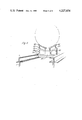
- FIG. 1 is a perspective view in elevation of the general arrangement of a preferred embodiment of the invention in which, for clarity, some parts of the equipment viz the force-exerting mechanism, the tube bundle support trolley and certain pieces of apparatus, have not been shown.
- FIG. 2 is a perspective view of the elongated frame structure of the extractor.
- FIG. 3 is a perspective view of the main clamps for connecting the extractor to the shell of the heat exchanger.
- FIG. 4 is a perspective view of the hydraulically operated force-exerting mechanism.
- FIG. 5 is a plan view, partly in section showing the pulling arms connected to a pulling plate.
- FIG. 6 is a perspective view of one form of stops used to control movement of the force-existing mechanism.
- FIG. 7 is a perspective view, partly cut away, of an alternative form of stops used to control movement of the force-exerting mechanism.
- FIG. 8 is a side elevation of the alternative form of stops shown in FIG. 7.
- FIG. 9 is a perspective view of a mobile carriage used to support the tube bundle.
- FIG. 10 is a perspective view in elevation of a lifting frame for lifting the extractor for use above ground level.
- FIG. 11 is a plan view in schematic form of the force-exerting mechanism connected to the shell of the heat exchanger.
- inboard end and outboard end mean respectively the end of the extractor which is nearer the heat exchanger and the end of the extractor which is further from the heat exchanger.
- a heat exchanger tube bundle extractor has a main structure which consists of two braced main beams 1 on top of which are welded channels 2 which form a track for bundle support trolleys 33 (described hereinafter).
- Four vertical struts 3 are attached to the main beams 1 by side members 4.
- the vertical struts 3 are provided at their upper ends with lifting eyes 5.
- each of the main beams 1 is provided at convenient intervals along its length with a number of further lifting eyes 6 (of which, for convenience, only one is shown in FIGS. 1 and 2).
- the provision of the lifting eyes 5 and 6 means that the structure can be readily balanced when it is lifted, no matter what the length of heat exchanger bundle being handled.
- a hinge support frame 7 consisting of two suitably braced vertical columns 8.
- At the inboard end of the main structure is a support frame 9 on which are mounted guide cylinders 10 for the main arms 11 (FIG. 3).
- the main structure contains a sub-frame within it which consists of two main arms 11, each constructed from a pair of channel beams, and having hinges 12 at the outboard end of the extractor. As shown in FIG. 1, the hinges 12 are supported in the support frame 7. The main arms 11 are fitted with connecting arms 13 and hydraulic clamps 14 at the inboard end. The position of main arms 11 is altered by operation of the guide cylinders 10 (FIG. 2).
- a fabricated sub-frame 15 is so made as to be slidable between the pair of channel beams which form the main arms 11 (See FIGS. 1 and 2).
- a main hydraulic cylinder 16 is mounted centrally on sub-frame 15. Extraction force exerted by cylinder 16 is transmitted via beam 17 to two pulling arms 18. Cylinder 16 is provided with an adjustable relief valve (not shown) so that the hydraulic pressure can be limited, if necessary.
- the arms 18, which are opened and shut using operating cylinder 19, are connectable to a pulling plate 20 which in use is bolted to the tube plate 21 of the tube bundle 22. Referring to FIG. 5, the pulling arms 18 are shown locked to the pulling plate 20 and ready for use. The rest position of arms 18 is indicated by the dotted lines in FIG.
- Two smaller hydraulic cylinders 23 mounted on a crossbar 24 are also connected to the sub-frame 15.
- Each cylinder 23 is provided with an air-pilot operated directional control valve (not shown) to control the pressure.
- the operating controls for the valves are conveniently mounted on a pendant or control console.
- FIG. 6 illustrates one form
- FIGS. 7 and 8 illustrate an alternative and preferred arrangement, of stops for the sub-frame 15.
- each stop 26 (of which, for clarity, only two are shown) has a small weight 27 which can be fitted in either one of two positions (depending on whether a tube bundle is being withdrawn or replaced), thus creating a reversible ratchet system. (In FIG. 6, the alternative position for weight 27 is shown by dotted lines). After the crossbar 24 has passed a stop 26, the latter will swing back and provide a firm stop (thrust surface) for the next stage of tube bundle removal or replacement.
- a series of connecting arms 28 is welded to each main arm 11 at intervals along its length.
- Corresponding series of chamfered stops (thrust surfaces) 29 are welded to main arms 11 immediately adjacent to and on the inner side of arms 28 (In FIG. 7, one arm 28 is shown partially cut away so as to illustrate a stop 29 more clearly).
- Supported in bearings mounted on each end of cross-bar 24 is a pivotable and reversible cam member 30 adapted to travel along the beam with the sub-frame 15. (Movement along the beam can be assisted by fitting rollers 31 to cross-bar 24--the rollers are omitted for clarity from FIGS. 4, 6 and 7, but are shown in FIG. 8).
- cam member 30 As the rounded end 32 of the cam member 30 reaches a stop 29, the cam member rides up over the chamfered edge of the stop.
- the opposite end of the cam member is designed to fit substantially flush against the stop 29.
- the cam member is reversible so that when the extractor unit reaches the limit of the structure in one direction, the cam member can be reversed so as to allow motion in the opposite mode.
- each trolley 33 has a rigid frame 34 supported on four wheels 35 and the trolley runs with the wheels 35 trapped in channel track 2 welded to the main beams 1.
- each trolley 33 has a pair of angled bundle support plates 36 each of which is supported by a single-acting cylinder hydraulic or screw jack 37.
- the provision of several positioning points 38 for the jacks 37 enables the angle of each support plate 36 to be varied so as to more adequately support tube bundles of a range of sizes.
- the height of the inner supports 39 for the plates 36 can be similarly varied to provide further adjustment and support.
- FIG. 10 illustrates an auxiliary piece of equipment for use with the extractor when the latter is used to extract tube bundles positioned at a height above ground level.
- the lifting frame illustrated in FIG. 10 consists of a rigid, rectangular frame 40 provided with lifting eyes 41, 42 at each of its four upper and four lower corners.
- the four lower eyes 42 engage the lifting eyes 5 on the struts 3 of the main structure by means of high tensile steel bolts and nuts.
- the four upper eyes 41 are used to connect the ropes 43 of a rope sling to a crane hook at point 44.
- the heat exchanger Before using the extractor, the heat exchanger is prepared by removal of its channel box cover and channel box, dome end cover and floating head when fitted. The pulling plate 20 is then bolted to the bundle tube plate 21 (see FIG. 11).
- the extractor itself is either suspended from a crane using an intermediate lifting frame (as illustrated in FIG. 10) or is supported from the ground or suitable elevated structure.
- Power for the extractor is provided by an air motor (not shown) permanently attached to the extractor structure.
- a hosed air supply is coupled to the extractor in a conventional way and the relief valve on the main cylinder 16 is adjusted to the correct setting. This setting is so chosen that the hydraulic pressure (and hence the extraction force) is limited to a value which does not overstress the tube bundle, particularly during the initial stages of withdrawal when greater force is likely to be needed than later in the withdrawal operation.
- the operation of the embodiment of the extractor which uses the bi-directional stops 26 will be described first.
- the series of bi-directional stops 26 are set to the appropriate operating mode using the weights 27.
- the appropriate outboard stop 26, that is the stop positioned at about the same distance from the tube plate 21 as the length of the tube bundle is reversed.
- the main arms clamps 14 are kept in a relaxed position and the main arms 11 are opened fully by operation of the guide cylinders 10.
- the extractor is then raised to the required elevation using a crane and lifting frame 40, and the main arms 11 are clamped with clamps 14 to the shell flange 45 (FIG. 11) on the exchanger centre line.
- Correct positioning of the clamps 14 relative to the shell flange 45 and to each other is of some importance if proper use is to be made of the pulling/pushing forces involved in the use of the extractor.
- This guide can take the form of one or more gauges to indicate the angle at which the arms 13 and clamps 14 are positioned.
- colour charts across which needles move in response to the position of the arms 13 and clamps 14 can be provided on the extractor so that all the operator has to do is to ensure that each needle is in the appropriately coloured section of its chart. Alignment of the apparatus in this way ensures that best use is made of the forces involved and that unwanted torque moments are avoided.
- the clamps 14 and guide cylinders 10 are then locked in position. Using cylinder 19, the pulling arms 18 are opened from the rest position and then closed around the arms of the plate 20 (FIGS. 4, 5 and 11), thus connecting the sub-frame 15 to the pulling plate 20 and the bundle tube plate 21.
- the final step in preparing the extractor for use is to ensure that the small hydraulic cylinders 23 are fully extended and that the sub-frame 15 is in contact at its inboard end with the stop formed by the outboard end 25 of the connecting arms 13.
- Pulling force is now applied to the tube bundle plate 21 by operating the main hydraulic cylinder 16, care being taken, as hereinbefore mentioned, to ensure that the cylinder pressure does not exceed the predetermined safe limit.
- the main hydraulic cylinder 16 is extended to its maximum travel.
- the small hydraulic cylinders 23 are retracted so as to continue extraction of the tube bundle until cylinders 23 are fully retracted.
- Cylinders 23 are then operated in the reverse direction, i.e. extended, until they have moved crossbar 24 beyond the next stop 26 (toward the outboard end of the extractor) and the stop has swung back into position.
- the sequence of operations involving retraction and then extension of cylinders 23 is repeated until the cross-bar 24 comes up against the outboard reversed stop 26.
- main cylinder 16 is used only in the initial freeing of the tube bundle from the heat exchanger. Withdrawal of the bundle is completed using the smaller hydraulic cylinders 23 which are used to exert a pushing force against the outboard side of stops 26 so that the corresponding reaction forces pull the sub-frame 15 and the tube bundle out of the heat exchanger.
- the tube bundle is locked to the extractor by moving the sub-frame 15 past its nearest adjacent stop by continued retraction of cylinders 23, followed by extension of cylinders 23 so as to cause the sub-frame 15 to bear against the back (i.e. the outboard side) of the stop which it has just passed.
- the support trolleys 33 are parked at the inboard end of the channel track 2.
- the trolley jacks 37 and inner supports 39 are adjusted to provide support for the tube bundle. As more and more of the bundle is extracted, so more and more trolleys are brought into use to support it.
- the rounded end 32 of cam member 30 should be directed toward the outboard end of the extractor so that its other end can lie flush against the stops 29 and so that as crossbar 24 is moved toward the outboard end of the extractor, the rounded end 32 can ride up and over the chamfered edges of the welded stops 29.
- the heat exchanger is positioned at a height above the ground and the loaded extractor must be lowered using a crane, it is desirable to check whether the loaded extractor is balanced before lowering takes place. This can be done by partially releasing the shell flange hydraulic clamps 14 and observing whether the extractor tilts.
- the extractor frame can be provided with a pendulum to indicate whether or not it is level. If it is necessary, the balance can be corrected by fine adjustment of the tube bundle using the main hydraulic cylinder 16.
- the clamps 14 are released fully and the loaded extractor lowered to the ground using the lifting frame 40.
- the tube bundle is released from the extractor for cleaning and repair by disconnecting the lifting frame 40 and releasing the pulling arms 18.
- the sequence of operations is reversed to replace a tube bundle within a heat exchanger.
- the small weights 27 are re-positioned (see FIG. 6).
- the pivotable cam member 30 is reversed so that its rounded end is directed toward the inboard end of the extractor.
- crossbar 24 bears against the inboard side of the stops 26 or 29 as pushing force is applied to the bundle.
- the sub-frame 15 can be provided with a brake to prevent inadvertent movement of the frame and tube bundle.
- a convenient form of brake is a retractable tenon on the underside of the sub-frame which is adapted to engage appropriately positioned slots either in or under main beam 11.
- the controls of the extractor can be interlocked to prevent inadvertent or conflicting operations during use of the extractor, for example so that clamps cannot be freed from the exchanger shell unless the brake on the extractor has been applied.
- the extractor according to this invention provides significant advantages over prior art extractors.
- the use of ropes and cables is avoided.
- the pulling/pushing forces are applied substantially symmetrically about the tube bundle centre line rather than, say, at the periphery of the tube bundle as has been the case in some earlier prior art extractors.
Landscapes
- Engineering & Computer Science (AREA)
- Mechanical Engineering (AREA)
- Automatic Assembly (AREA)
- Hand Tools For Fitting Together And Separating, Or Other Hand Tools (AREA)
- Processing And Handling Of Plastics And Other Materials For Molding In General (AREA)
Applications Claiming Priority (2)
| Application Number | Priority Date | Filing Date | Title |
|---|---|---|---|
| GB28985/77 | 1977-07-11 | ||
| GB2898577 | 1977-07-11 |
Publications (1)
| Publication Number | Publication Date |
|---|---|
| US4227854A true US4227854A (en) | 1980-10-14 |
Family
ID=10284415
Family Applications (1)
| Application Number | Title | Priority Date | Filing Date |
|---|---|---|---|
| US05/923,443 Expired - Lifetime US4227854A (en) | 1977-07-11 | 1978-07-10 | Apparatus for removing heat exchanger tube bundles |
Country Status (10)
| Country | Link |
|---|---|
| US (1) | US4227854A (fr) |
| JP (1) | JPS5439249A (fr) |
| AU (1) | AU527358B2 (fr) |
| BE (1) | BE868806A (fr) |
| CA (1) | CA1094302A (fr) |
| DE (1) | DE2830233A1 (fr) |
| FR (1) | FR2397614A1 (fr) |
| IT (1) | IT1097499B (fr) |
| NL (1) | NL7807281A (fr) |
| NO (1) | NO150237C (fr) |
Cited By (27)
| Publication number | Priority date | Publication date | Assignee | Title |
|---|---|---|---|---|
| US4299531A (en) * | 1979-06-22 | 1981-11-10 | Edmonton Exchanger And Refinery Services Ltd. | Carriage for supporting a tube bundle on a tube bundle puller |
| US4312124A (en) * | 1979-11-27 | 1982-01-26 | Westinghouse Electric Corp. | Multiple tube pulling apparatus |
| US4323398A (en) * | 1980-04-07 | 1982-04-06 | Andrew Simon | Performing maintenance operations on heat exchanger tube bundles |
| US4358242A (en) * | 1979-12-11 | 1982-11-09 | Industrial And Overseas Securities Limited | Core extraction and insertion apparatus |
| US4571820A (en) * | 1984-02-17 | 1986-02-25 | Ishikawajima-Harima Jukogyo Kabushiki Kaisha | Device for disassembling and reassembling a main steam isolation valve of a nuclear reactor |
| US4575305A (en) * | 1983-11-18 | 1986-03-11 | Bon Ton Rolle Limited | Truck mounted tube bundle pulling apparatus |
| US4666365A (en) * | 1983-11-18 | 1987-05-19 | Bon Ton Rolle Limited | Tube bundle pulling apparatus |
| US4707912A (en) * | 1985-06-14 | 1987-11-24 | Brown Boveri Reaktor Gmbh | Crash protection apparatus for a device for pulling a tube out of a tube sheet of a heat exchanger |
| US4869638A (en) * | 1987-11-04 | 1989-09-26 | Serv-Tech, Inc. | Aerial bundle puller |
| US5032054A (en) * | 1987-11-04 | 1991-07-16 | Serv-Tech, Inc. | Aerial bundle puller |
| EP0555571A1 (fr) * | 1991-01-17 | 1993-08-18 | Ohmstede Mechanical Services, Inc. | Extracteur détachable, actionné par une grue ou une flèche pour les faisceaux des tubes d'échangeurs thermiques |
| US5562400A (en) * | 1994-05-12 | 1996-10-08 | Travis; Bobby J. | Self-propelled lifting apparatus |
| US6685423B1 (en) | 2000-09-25 | 2004-02-03 | Starcon International, Inc. | Method and apparatus for extracting and installing heat exchanger bundles |
| US6729833B2 (en) * | 2000-09-25 | 2004-05-04 | Starcon International, Inc. | Method and apparatus for extracting and installing heat exchanger bundles |
| WO2004010069A3 (fr) * | 2002-07-23 | 2004-08-12 | Starcon International Inc | Procede et appareil permettant le retrait et l'installation de faisceaux d'echangeur de chaleur |
| US7080864B2 (en) | 2002-05-03 | 2006-07-25 | Drilltec Patents & Technologies Company, Inc. | Apparatus for shipping and storing elongated members |
| ITMI20082004A1 (it) * | 2008-11-12 | 2010-05-13 | Maus Italia F Agostino & C S A S | Dispositivo e procedimento per l inserzione di un fascio tubiero in un mantello di uno scambiatore di calore |
| CN101813311A (zh) * | 2010-05-06 | 2010-08-25 | 哈尔滨哈锅锅炉容器工程有限责任公司 | 余热模块式锅炉的受热面总成 |
| US20110110755A1 (en) * | 2009-11-11 | 2011-05-12 | Peinemann Equipment B.V. | Device and Method for Removing a Bundle from a Heat Exchanger |
| US20110223116A1 (en) * | 2010-03-09 | 2011-09-15 | Penn-Century, Inc. | Apparatus and method for aerosol delivery to the lungs or other locations of the body |
| WO2011110844A1 (fr) * | 2010-03-08 | 2011-09-15 | Ross Offshore Consultancy Limited | Dispositif modulaire pour extraire un faisceau d'échangeur de chaleur |
| EP2799803A1 (fr) * | 2013-05-03 | 2014-11-05 | Howden UK Limited | Système de levage pour paniers d'élément à profil bas pour préchauffeurs d'air régénératifs rotatifs |
| US20160033210A1 (en) * | 2014-07-31 | 2016-02-04 | Altex Industries Inc. | Support for a heat exchanger tube bundle |
| US10280046B2 (en) * | 2014-08-06 | 2019-05-07 | Idrojet Srl | Machine for aerial handling of loads |
| US10399192B2 (en) * | 2016-08-12 | 2019-09-03 | Chiyoda Corporation | Machinery installation method, machinery inspection method, machinery linkage inspection method, and supporting structures |
| IT201900001825A1 (it) * | 2019-02-08 | 2020-08-08 | Maus Italia S P A | Estrattore di fasci tubieri di scambiatori di calore |
| US11187467B2 (en) * | 2019-10-08 | 2021-11-30 | Air Products And Chemicals, Inc. | Heat exchange system and method of assembly |
Families Citing this family (3)
| Publication number | Priority date | Publication date | Assignee | Title |
|---|---|---|---|---|
| DE3046467A1 (de) * | 1980-12-10 | 1982-07-01 | Ludwig Ing.(grad.) 8079 Egweil Bauch | Vorrichtung zum herausziehen und hineinschieben von rohrbuendeln bei waermetauschern |
| JPS62246440A (ja) * | 1986-04-18 | 1987-10-27 | Ishikawajima Harima Heavy Ind Co Ltd | 伝熱管の組込み方法 |
| CN112045626B (zh) * | 2020-08-21 | 2022-03-11 | 中国长江三峡集团有限公司 | 垂直升船机大型卧倒式平面闸门支铰轴承高效检修装置及方法 |
Citations (8)
| Publication number | Priority date | Publication date | Assignee | Title |
|---|---|---|---|---|
| US2318567A (en) * | 1940-04-23 | 1943-05-04 | Campbell Soup Co | Conveyer release mechanism |
| GB951564A (en) * | 1962-07-16 | 1964-03-04 | Texaco Development Corp | Apparatus for removing heat exchanger tube bundles |
| GB963243A (en) * | 1961-10-02 | 1964-07-08 | California Research Corp | Tube bundle extractor for heat exchangers |
| US3567044A (en) * | 1968-09-03 | 1971-03-02 | Bobby J Travis | Apparatus for force application |
| US3870279A (en) * | 1972-09-11 | 1975-03-11 | Allied Steel Tractor Prod Inc | Stepper carriage advancement system |
| US3958698A (en) * | 1973-05-21 | 1976-05-25 | N.V. Machinefabriek Stork-Jaffa | Pipe bundle extracting/inserting device |
| US4032112A (en) * | 1973-03-07 | 1977-06-28 | Enor Nominees Pty Limited | Climbing jack |
| US4053062A (en) * | 1975-09-26 | 1977-10-11 | Travis Bobby J | Tube bundle extractor for use with heat exchangers |
Family Cites Families (2)
| Publication number | Priority date | Publication date | Assignee | Title |
|---|---|---|---|---|
| NL7307083A (fr) * | 1973-05-21 | 1974-11-25 | ||
| DE2336470A1 (de) * | 1973-07-18 | 1975-02-06 | Siac Ges Fuer Elektrotechnik U | Zug-drueckvorrichtung fuer waermetauscher |
-
1978
- 1978-06-30 NO NO782270A patent/NO150237C/no unknown
- 1978-07-05 NL NL7807281A patent/NL7807281A/xx not_active Application Discontinuation
- 1978-07-06 IT IT25434/78A patent/IT1097499B/it active
- 1978-07-06 AU AU37799/78A patent/AU527358B2/en not_active Expired
- 1978-07-06 BE BE189131A patent/BE868806A/fr not_active IP Right Cessation
- 1978-07-07 CA CA307,012A patent/CA1094302A/fr not_active Expired
- 1978-07-10 US US05/923,443 patent/US4227854A/en not_active Expired - Lifetime
- 1978-07-10 FR FR7820566A patent/FR2397614A1/fr active Granted
- 1978-07-10 DE DE19782830233 patent/DE2830233A1/de not_active Withdrawn
- 1978-07-11 JP JP8450678A patent/JPS5439249A/ja active Pending
Patent Citations (8)
| Publication number | Priority date | Publication date | Assignee | Title |
|---|---|---|---|---|
| US2318567A (en) * | 1940-04-23 | 1943-05-04 | Campbell Soup Co | Conveyer release mechanism |
| GB963243A (en) * | 1961-10-02 | 1964-07-08 | California Research Corp | Tube bundle extractor for heat exchangers |
| GB951564A (en) * | 1962-07-16 | 1964-03-04 | Texaco Development Corp | Apparatus for removing heat exchanger tube bundles |
| US3567044A (en) * | 1968-09-03 | 1971-03-02 | Bobby J Travis | Apparatus for force application |
| US3870279A (en) * | 1972-09-11 | 1975-03-11 | Allied Steel Tractor Prod Inc | Stepper carriage advancement system |
| US4032112A (en) * | 1973-03-07 | 1977-06-28 | Enor Nominees Pty Limited | Climbing jack |
| US3958698A (en) * | 1973-05-21 | 1976-05-25 | N.V. Machinefabriek Stork-Jaffa | Pipe bundle extracting/inserting device |
| US4053062A (en) * | 1975-09-26 | 1977-10-11 | Travis Bobby J | Tube bundle extractor for use with heat exchangers |
Non-Patent Citations (1)
| Title |
|---|
| Hydro-Extractors, Inc. Brochure, 1973. * |
Cited By (34)
| Publication number | Priority date | Publication date | Assignee | Title |
|---|---|---|---|---|
| US4299531A (en) * | 1979-06-22 | 1981-11-10 | Edmonton Exchanger And Refinery Services Ltd. | Carriage for supporting a tube bundle on a tube bundle puller |
| US4312124A (en) * | 1979-11-27 | 1982-01-26 | Westinghouse Electric Corp. | Multiple tube pulling apparatus |
| US4358242A (en) * | 1979-12-11 | 1982-11-09 | Industrial And Overseas Securities Limited | Core extraction and insertion apparatus |
| US4323398A (en) * | 1980-04-07 | 1982-04-06 | Andrew Simon | Performing maintenance operations on heat exchanger tube bundles |
| US4575305A (en) * | 1983-11-18 | 1986-03-11 | Bon Ton Rolle Limited | Truck mounted tube bundle pulling apparatus |
| US4666365A (en) * | 1983-11-18 | 1987-05-19 | Bon Ton Rolle Limited | Tube bundle pulling apparatus |
| US4571820A (en) * | 1984-02-17 | 1986-02-25 | Ishikawajima-Harima Jukogyo Kabushiki Kaisha | Device for disassembling and reassembling a main steam isolation valve of a nuclear reactor |
| US4707912A (en) * | 1985-06-14 | 1987-11-24 | Brown Boveri Reaktor Gmbh | Crash protection apparatus for a device for pulling a tube out of a tube sheet of a heat exchanger |
| US4869638A (en) * | 1987-11-04 | 1989-09-26 | Serv-Tech, Inc. | Aerial bundle puller |
| US5032054A (en) * | 1987-11-04 | 1991-07-16 | Serv-Tech, Inc. | Aerial bundle puller |
| EP0555571A1 (fr) * | 1991-01-17 | 1993-08-18 | Ohmstede Mechanical Services, Inc. | Extracteur détachable, actionné par une grue ou une flèche pour les faisceaux des tubes d'échangeurs thermiques |
| US5562400A (en) * | 1994-05-12 | 1996-10-08 | Travis; Bobby J. | Self-propelled lifting apparatus |
| US6685423B1 (en) | 2000-09-25 | 2004-02-03 | Starcon International, Inc. | Method and apparatus for extracting and installing heat exchanger bundles |
| US6729833B2 (en) * | 2000-09-25 | 2004-05-04 | Starcon International, Inc. | Method and apparatus for extracting and installing heat exchanger bundles |
| US7080864B2 (en) | 2002-05-03 | 2006-07-25 | Drilltec Patents & Technologies Company, Inc. | Apparatus for shipping and storing elongated members |
| WO2004010069A3 (fr) * | 2002-07-23 | 2004-08-12 | Starcon International Inc | Procede et appareil permettant le retrait et l'installation de faisceaux d'echangeur de chaleur |
| ITMI20082004A1 (it) * | 2008-11-12 | 2010-05-13 | Maus Italia F Agostino & C S A S | Dispositivo e procedimento per l inserzione di un fascio tubiero in un mantello di uno scambiatore di calore |
| US20110110755A1 (en) * | 2009-11-11 | 2011-05-12 | Peinemann Equipment B.V. | Device and Method for Removing a Bundle from a Heat Exchanger |
| US8317455B2 (en) * | 2009-11-11 | 2012-11-27 | Peinemann Equipment B.V. | Device and method for removing a bundle from a heat exchanger |
| WO2011110844A1 (fr) * | 2010-03-08 | 2011-09-15 | Ross Offshore Consultancy Limited | Dispositif modulaire pour extraire un faisceau d'échangeur de chaleur |
| US8974771B2 (en) | 2010-03-09 | 2015-03-10 | Penn-Century, Inc. | Apparatus and method for aerosol delivery to the lungs or other locations of the body |
| US20110223116A1 (en) * | 2010-03-09 | 2011-09-15 | Penn-Century, Inc. | Apparatus and method for aerosol delivery to the lungs or other locations of the body |
| CN101813311A (zh) * | 2010-05-06 | 2010-08-25 | 哈尔滨哈锅锅炉容器工程有限责任公司 | 余热模块式锅炉的受热面总成 |
| US9352938B2 (en) | 2013-05-03 | 2016-05-31 | Howden Uk Limited | Lifting system for low profile element baskets for rotary regenerative air preheaters |
| EP2799803A1 (fr) * | 2013-05-03 | 2014-11-05 | Howden UK Limited | Système de levage pour paniers d'élément à profil bas pour préchauffeurs d'air régénératifs rotatifs |
| US20160033210A1 (en) * | 2014-07-31 | 2016-02-04 | Altex Industries Inc. | Support for a heat exchanger tube bundle |
| US9612063B2 (en) * | 2014-07-31 | 2017-04-04 | Altex Industries Inc. | Support for a heat exchanger tube bundle |
| US10280046B2 (en) * | 2014-08-06 | 2019-05-07 | Idrojet Srl | Machine for aerial handling of loads |
| US10399192B2 (en) * | 2016-08-12 | 2019-09-03 | Chiyoda Corporation | Machinery installation method, machinery inspection method, machinery linkage inspection method, and supporting structures |
| IT201900001825A1 (it) * | 2019-02-08 | 2020-08-08 | Maus Italia S P A | Estrattore di fasci tubieri di scambiatori di calore |
| WO2020161756A1 (fr) * | 2019-02-08 | 2020-08-13 | Maus Italia S.P.A. | Extracteur de faisceaux de tubes pour échangeurs de chaleur |
| US11187467B2 (en) * | 2019-10-08 | 2021-11-30 | Air Products And Chemicals, Inc. | Heat exchange system and method of assembly |
| US11391512B2 (en) | 2019-10-08 | 2022-07-19 | Air Products And Chemicals, Inc. | Heat exchange system and method of assembly |
| US11859903B2 (en) | 2019-10-08 | 2024-01-02 | Air Products And Chemicals, Inc. | Heat exchange system and method of assembly |
Also Published As
| Publication number | Publication date |
|---|---|
| IT1097499B (it) | 1985-08-31 |
| CA1094302A (fr) | 1981-01-27 |
| NO782270L (no) | 1979-01-12 |
| AU527358B2 (en) | 1983-03-03 |
| NO150237B (no) | 1984-06-04 |
| JPS5439249A (en) | 1979-03-26 |
| NL7807281A (nl) | 1979-01-15 |
| FR2397614A1 (fr) | 1979-02-09 |
| NO150237C (no) | 1984-09-12 |
| BE868806A (fr) | 1979-01-08 |
| AU3779978A (en) | 1980-01-10 |
| FR2397614B1 (fr) | 1983-12-02 |
| DE2830233A1 (de) | 1979-01-25 |
| IT7825434A0 (it) | 1978-07-06 |
Similar Documents
| Publication | Publication Date | Title |
|---|---|---|
| CA1094302A (fr) | Dispositif pour l'extraction du faisceau de tubes d'un echangeur de chaleur | |
| DE68906235T2 (de) | Kran zum Heben und Aussetzen von Booten auf einem Kai bzw. von einem Kai. | |
| US3630066A (en) | Apparatus for returning vehicle body and frame components to their original locations during repair and servicing of vehicles | |
| US4392524A (en) | Apparatus for removing a tube core from and inserting same into a heat exchanger | |
| JPS62146387A (ja) | 掘削塔の掘削シヤフトの垂直ラツキング方法及び装置 | |
| FI82132C (fi) | Apparat foer utfoerande av aotgaerder pao en undervattensventil. | |
| US4865513A (en) | Portable manway cover handling apparatus | |
| CN116969303B (zh) | 一种钢屋盖吊装设备 | |
| DE3410949C2 (de) | Metallurgisches Gefäß, insbesondere auswechselbarer Stahlwerkskonverter | |
| DE3342265A1 (de) | Demontagevorrichtung fuer einen turmkranausleger | |
| GB1564493A (en) | Apparatus for supporting pipelines | |
| DE2029681A1 (de) | Krangehänge | |
| GB2101701A (en) | Connecting submerged conduit sections | |
| EP0585448B1 (fr) | Appareil de remplacement d'une tete d'injection en exploitation petroliere au large | |
| CN214329949U (zh) | 一种竖向钢筋网片绑扎用竖向钢筋吊装结构 | |
| GB2056408A (en) | Jacking device | |
| DE102022104895A1 (de) | Hebevorrichtung zum Anheben eines Rotorblattes und Haltevorrichtung dafür | |
| CN221403007U (zh) | 一种锅炉固定支架 | |
| CN219823466U (zh) | 一种钢梁构件翻转装置 | |
| CN220352637U (zh) | 一种桥梁护栏施工用移动挂篮 | |
| EP1505249B1 (fr) | Dispositif de démontage et de remplacement des éléments encombrants et lourds | |
| CN223922003U (zh) | 一种钢结构桥梁支撑架 | |
| RU2295468C1 (ru) | Транспортно-установочный агрегат | |
| CN113233375B (zh) | 一种篦架用夹持小车 | |
| GB2063753A (en) | Core extraction and insertion apparatus |