US4233115A - Safety apparatus for a nuclear reactor - Google Patents
Safety apparatus for a nuclear reactor Download PDFInfo
- Publication number
- US4233115A US4233115A US05/894,002 US89400278A US4233115A US 4233115 A US4233115 A US 4233115A US 89400278 A US89400278 A US 89400278A US 4233115 A US4233115 A US 4233115A
- Authority
- US
- United States
- Prior art keywords
- operating rod
- head
- absorbing element
- armature
- length
- Prior art date
- Legal status (The legal status is an assumption and is not a legal conclusion. Google has not performed a legal analysis and makes no representation as to the accuracy of the status listed.)
- Expired - Lifetime
Links
- 239000002184 metal Substances 0.000 claims abstract description 11
- 229910052751 metal Inorganic materials 0.000 claims abstract description 11
- 230000005484 gravity Effects 0.000 claims abstract description 6
- 238000006073 displacement reaction Methods 0.000 claims description 5
- 230000000694 effects Effects 0.000 claims 6
- 229910001338 liquidmetal Inorganic materials 0.000 description 6
- 238000000926 separation method Methods 0.000 description 5
- DGAQECJNVWCQMB-PUAWFVPOSA-M Ilexoside XXIX Chemical compound C[C@@H]1CC[C@@]2(CC[C@@]3(C(=CC[C@H]4[C@]3(CC[C@@H]5[C@@]4(CC[C@@H](C5(C)C)OS(=O)(=O)[O-])C)C)[C@@H]2[C@]1(C)O)C)C(=O)O[C@H]6[C@@H]([C@H]([C@@H]([C@H](O6)CO)O)O)O.[Na+] DGAQECJNVWCQMB-PUAWFVPOSA-M 0.000 description 3
- XEEYBQQBJWHFJM-UHFFFAOYSA-N Iron Chemical compound [Fe] XEEYBQQBJWHFJM-UHFFFAOYSA-N 0.000 description 3
- 230000000712 assembly Effects 0.000 description 3
- 238000000429 assembly Methods 0.000 description 3
- 238000006243 chemical reaction Methods 0.000 description 3
- 238000001816 cooling Methods 0.000 description 3
- 239000000463 material Substances 0.000 description 3
- 230000001681 protective effect Effects 0.000 description 3
- 229910052708 sodium Inorganic materials 0.000 description 3
- 239000011734 sodium Substances 0.000 description 3
- 230000002159 abnormal effect Effects 0.000 description 2
- 230000007423 decrease Effects 0.000 description 2
- 239000000446 fuel Substances 0.000 description 2
- 230000001105 regulatory effect Effects 0.000 description 2
- 239000010935 stainless steel Substances 0.000 description 2
- 229910001220 stainless steel Inorganic materials 0.000 description 2
- 239000006096 absorbing agent Substances 0.000 description 1
- 229910045601 alloy Inorganic materials 0.000 description 1
- 239000000956 alloy Substances 0.000 description 1
- 238000010276 construction Methods 0.000 description 1
- 230000001276 controlling effect Effects 0.000 description 1
- 230000007812 deficiency Effects 0.000 description 1
- 230000002950 deficient Effects 0.000 description 1
- 239000007788 liquid Substances 0.000 description 1
- 239000011344 liquid material Substances 0.000 description 1
- 238000012986 modification Methods 0.000 description 1
- 230000004048 modification Effects 0.000 description 1
- 230000007935 neutral effect Effects 0.000 description 1
- 239000003758 nuclear fuel Substances 0.000 description 1
- 230000002093 peripheral effect Effects 0.000 description 1
- 230000009467 reduction Effects 0.000 description 1
- 230000035939 shock Effects 0.000 description 1
Images

Classifications
-
- G—PHYSICS
- G21—NUCLEAR PHYSICS; NUCLEAR ENGINEERING
- G21C—NUCLEAR REACTORS
- G21C7/00—Control of nuclear reaction
- G21C7/06—Control of nuclear reaction by application of neutron-absorbing material, i.e. material with absorption cross-section very much in excess of reflection cross-section
- G21C7/08—Control of nuclear reaction by application of neutron-absorbing material, i.e. material with absorption cross-section very much in excess of reflection cross-section by displacement of solid control elements, e.g. control rods
- G21C7/12—Means for moving control elements to desired position
-
- G—PHYSICS
- G21—NUCLEAR PHYSICS; NUCLEAR ENGINEERING
- G21C—NUCLEAR REACTORS
- G21C9/00—Emergency protection arrangements structurally associated with the reactor, e.g. safety valves provided with pressure equalisation devices
- G21C9/02—Means for effecting very rapid reduction of the reactivity factor under fault conditions, e.g. reactor fuse; Control elements having arrangements activated in an emergency
- G21C9/027—Means for effecting very rapid reduction of the reactivity factor under fault conditions, e.g. reactor fuse; Control elements having arrangements activated in an emergency by fast movement of a solid, e.g. pebbles
-
- Y—GENERAL TAGGING OF NEW TECHNOLOGICAL DEVELOPMENTS; GENERAL TAGGING OF CROSS-SECTIONAL TECHNOLOGIES SPANNING OVER SEVERAL SECTIONS OF THE IPC; TECHNICAL SUBJECTS COVERED BY FORMER USPC CROSS-REFERENCE ART COLLECTIONS [XRACs] AND DIGESTS
- Y02—TECHNOLOGIES OR APPLICATIONS FOR MITIGATION OR ADAPTATION AGAINST CLIMATE CHANGE
- Y02E—REDUCTION OF GREENHOUSE GAS [GHG] EMISSIONS, RELATED TO ENERGY GENERATION, TRANSMISSION OR DISTRIBUTION
- Y02E30/00—Energy generation of nuclear origin
- Y02E30/30—Nuclear fission reactors
Definitions
- the present invention relates to a safety apparatus for a nuclear reactor, particularly a fast neutron reactor whose core, cooled by the circulation of a liquid metal, in general sodium, has a central area called the fuel area and a peripheral covering area surrounding the said central area.
- the disconnectable linkage between the head of the absorbing element and the end of the operating rod is arranged, with the element in the upper position, in the upper part and at least partly within the open container, the absorbing element extending into said container in the core covering area outside the central area.
- the disconnectable linkage is realised by means of an electromagnet armature fitted at the lower end of the operating rod.
- the absorbing element is constructed in articulated form by means of absorbing links joined to one another beneath the head of the element and cooperating in the lower engagement position in the core with an internal abutment of the container, whereby a shock absorber system is preferably provided at the end of the travel.
- the present invention relates to a safety apparatus which meets this requirement.
- this apparatus relates more particularly to an absorbing element comprising a support head joined by a disconnectable linkage constituted by the armature of an electromagnet to the end of an axially movable vertical operating rod, said linkage being such that in the case of a disconnection the absorbing element slides by gravity in a passage bounded in an open container through the reactor core, wherein the operating rod is associated with a metal member having an expansion coefficient which is significantly higher than that of the armature of the electromagnet and in the case of an abnormal temperature rise it exerts a separating force between the head of the absorbing element and the operating rod.
- the metal member comprises a jacket or sleeve carried by the operating rod and surrounding with a clearance the end of said rod, whereby its edge is flush with the head of the absorbing element.
- the metal member comprises a finger disposed axially in the rod and traversing the armature of the electromagnet
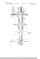
- FIG. 1 a diagrammatic sectional view of the core of a fast neutron reactor with an axially movable operating rod for controlling the position of the absorbing element;
- FIG. 2 a larger scale detail of the end of the operating rod and the head of the absorbing element illustrating the safety apparatus according to the invention in a first embodiment
- FIG. 3 a view identical to that of FIG. 2 illustrating another embodiment of the apparatus.
- the reference numeral 1 diagrammatically designates the core of a nuclear reactor, more particularly of the fast neutron type.
- This core is immersed in an appropriate volume 2 of a liquid cooling metal which is generally sodium and contained within a not shown vessel.
- a neutral gas cushion 3 Above the sodium in the vessel is provided a neutral gas cushion 3, whilst the upper part of said vessel is sealed by a horizontal protective slab 4 comprising a lower metal base plate 5 and a sufficient thickness 6 of a protective material such as concrete.
- the fissionable and fertile assemblies necessary for establishing and maintaining the nuclear reaction are distributed in known manner within core 1. These assemblies are not shown in the drawings for reasons of clarity. It is only possible to see the upper open end of a container 7 positioned among the other assemblies of the core and having the same geometrical shape as the latter and within which slides an absorbing element 8. The upper part of the latter is provided with a head 9 permitting the attachment of element 8 with the lower end of an axial control rod 10.
- the detailed construction of absorbing element 8 is preferably the same as that described and represented in the U.S. patent application Ser. No. 521, 900 filed on Nov. 7, 1974.
- connection between the axial operating rod 10 and head 9 of absorbing elements 8 is disconnectable and is provided by means of an electromagnet 11 in order to permit in the manner described in the above-mentioned patent a violent drop into container 7 by simply interrupting the power supply to the electromagnet.
- the displacement of rod 10 outside container 7 is effective through the sliding of said rod within a guide tube 12, whereby the rod has at its upper end a control system 13 in this case constituted by a nut 14 cooperating with a threaded rod 15.
- any equivalent control system constituted for example by a rack and pinion mechanism.
- Laterally nut 14 has a key 16 sliding in a groove 17 of guide tube 12 in order to transform the rotary movement of threaded rod 15 into an axial displacement movement for rod 10.
- the assembly constituted by guide rod 12 and rod 10 is carried by a plug member 18 which engages in an appropriate passage provided in the protective slab 4.
- FIG. 2 illustrates on a larger scale the lower end of operating rod 10 provided with the electromagnet 11.
- the latter is surrounded, whilst leaving an appropriate clearance, by a coaxial jacket 19 made from a material (metal or alloy) having an expansion coefficient which is significantly higher than that of the core of the electromagnet.
- the lower end 20 of jacket 19 is flush with head 9 of element 8 in such a way that under normal operating conditions armature 21 of electromagnet 11 provides an air gap 22 which maintains element 8.
- any temperature rise in the core for example, due to a blockage of the liquid metal circulating pumps leads to an increase in the longitudinal dimensions of jacket 19 so that end 20 thereof thrusts the head 9 of absorbing element 8, thereby bringing about the separation of its connection with armature 21 and the drop of said element into container 7.
- the disengagement temperature of element 8 can easily be regulated as a function of the initial position of jacket 19 and the magnitude of the gap 22 of the electromagnet.
- the metal member carried by electromagnet 11 is in the form of an axial rod 23 traversing the armature 21 of the electromagnet and then again bears on head 9 of absorbing element 8 in such a way as to cause as hereinbefore as a result of a temperature rise the separation of the connection with the operating rod and the drop into the core.
- the jacket or axial finger on the head of the actual absorbing element and not around or in the electromagnet in order to bring about in an identical manner the separation of said rod and said element. It should be noted that an appropriate clearance 30 (FIG. 2) is always provided between jacket 19 and electromagnet 11 in order to permit the corresponding retraction of the jacket during temperature reductions.
- the ratio of the expansion coefficients between the material constituting the electromagnet preferably made from ARMCO iron or very pure electrolytic iron and that of the axial finger or jacket mounted in the electromagnet and constituted by stainless steel is equal to or close to 2, these coefficients being of the order of 1 mm/m/100° C. for ARMCO iron and 2 mm/m/100° C. for stainless steel type "316L".
- a 500 mm long cylindrical jacket will have an elongation in excess of 5/10 mm compared with that of the electromagnet if the liquid metal temperature rises from 545° C., which is the normal operating temperature, to for example 645° C. which is very adequate for ensuring the disconnecton of the electromagnet and the absorbing element with a sufficiently small response time.
Landscapes
- Physics & Mathematics (AREA)
- Engineering & Computer Science (AREA)
- Plasma & Fusion (AREA)
- General Engineering & Computer Science (AREA)
- High Energy & Nuclear Physics (AREA)
- Chemical & Material Sciences (AREA)
- Chemical Kinetics & Catalysis (AREA)
- Structure Of Emergency Protection For Nuclear Reactors (AREA)
- Magnetic Resonance Imaging Apparatus (AREA)
- Monitoring And Testing Of Nuclear Reactors (AREA)
Applications Claiming Priority (2)
| Application Number | Priority Date | Filing Date | Title |
|---|---|---|---|
| FR7711418 | 1977-04-15 | ||
| FR7711418A FR2387495A1 (fr) | 1977-04-15 | 1977-04-15 | Dispositif de securite pour reacteur nucleaire |
Publications (1)
| Publication Number | Publication Date |
|---|---|
| US4233115A true US4233115A (en) | 1980-11-11 |
Family
ID=9189467
Family Applications (1)
| Application Number | Title | Priority Date | Filing Date |
|---|---|---|---|
| US05/894,002 Expired - Lifetime US4233115A (en) | 1977-04-15 | 1978-04-06 | Safety apparatus for a nuclear reactor |
Country Status (8)
| Country | Link |
|---|---|
| US (1) | US4233115A (it) |
| JP (1) | JPS53129797A (it) |
| BE (1) | BE865945A (it) |
| DE (1) | DE2815424C2 (it) |
| ES (1) | ES468781A1 (it) |
| FR (1) | FR2387495A1 (it) |
| GB (1) | GB1583306A (it) |
| IT (1) | IT1108625B (it) |
Cited By (3)
| Publication number | Priority date | Publication date | Assignee | Title |
|---|---|---|---|---|
| US4423002A (en) * | 1979-12-19 | 1983-12-27 | Framatome | Apparatus for controlling a nuclear reactor by vertical displacement of a unit absorbing neutrons |
| US4645639A (en) * | 1984-03-30 | 1987-02-24 | The United States Of America As Represented By The United States Department Of Energy | Pushrod assembly |
| US5114663A (en) * | 1990-08-16 | 1992-05-19 | Doryokuro Kakunenryo Kaihatsu Jigyodan | Electromagnet for nuclear reactor shutdown system |
Families Citing this family (3)
| Publication number | Priority date | Publication date | Assignee | Title |
|---|---|---|---|---|
| JPS56137271A (en) * | 1980-03-31 | 1981-10-27 | Tokyo Shibaura Electric Co | Nuclear reactor shutdown device |
| JPS5767892A (en) * | 1980-10-15 | 1982-04-24 | Tokyo Shibaura Electric Co | Nuclear reactor shutdown device |
| GB9017682D0 (en) * | 1990-08-13 | 1990-09-26 | Nnc Ltd | Nuclear reactors |
Citations (5)
| Publication number | Priority date | Publication date | Assignee | Title |
|---|---|---|---|---|
| GB965014A (en) * | 1962-03-02 | 1964-07-29 | Atomic Energy Authority Uk | Nuclear reactor control |
| US3546996A (en) * | 1969-04-10 | 1970-12-15 | Atomic Energy Commission | Release latch actuated by temperature excursion |
| US3976540A (en) * | 1975-04-03 | 1976-08-24 | The United States Of America As Represented By The United States Energy Research And Development Administration | Magnetic latch trigger for inherent shutdown assembly |
| US3976543A (en) * | 1975-11-14 | 1976-08-24 | The United States Of America As Represented By The United States Energy Research And Development Administration | Temperature actuated shutdown assembly for a nuclear reactor |
| US4019954A (en) * | 1974-11-07 | 1977-04-26 | Commissariat A L'energie Atomique | Safety device for a nuclear reactor and especially a fast reactor |
Family Cites Families (2)
| Publication number | Priority date | Publication date | Assignee | Title |
|---|---|---|---|---|
| IT957627B (it) * | 1972-04-14 | 1973-10-20 | Cnen | Dispositivo elettromagnetico di sicurezza per l agganciamento delle barre di controllo e sicurez za di un reattore nucleare con logi ca di sgancio intrinseca |
| FR2251079B1 (it) * | 1973-11-08 | 1976-12-03 | Commissariat Energie Atomique |
-
1977
- 1977-04-15 FR FR7711418A patent/FR2387495A1/fr active Granted
-
1978
- 1978-03-31 GB GB12713/78A patent/GB1583306A/en not_active Expired
- 1978-04-06 US US05/894,002 patent/US4233115A/en not_active Expired - Lifetime
- 1978-04-10 DE DE2815424A patent/DE2815424C2/de not_active Expired
- 1978-04-12 JP JP4221878A patent/JPS53129797A/ja active Pending
- 1978-04-13 ES ES468781A patent/ES468781A1/es not_active Expired
- 1978-04-13 BE BE186762A patent/BE865945A/xx not_active IP Right Cessation
- 1978-04-14 IT IT67844/78A patent/IT1108625B/it active
Patent Citations (5)
| Publication number | Priority date | Publication date | Assignee | Title |
|---|---|---|---|---|
| GB965014A (en) * | 1962-03-02 | 1964-07-29 | Atomic Energy Authority Uk | Nuclear reactor control |
| US3546996A (en) * | 1969-04-10 | 1970-12-15 | Atomic Energy Commission | Release latch actuated by temperature excursion |
| US4019954A (en) * | 1974-11-07 | 1977-04-26 | Commissariat A L'energie Atomique | Safety device for a nuclear reactor and especially a fast reactor |
| US3976540A (en) * | 1975-04-03 | 1976-08-24 | The United States Of America As Represented By The United States Energy Research And Development Administration | Magnetic latch trigger for inherent shutdown assembly |
| US3976543A (en) * | 1975-11-14 | 1976-08-24 | The United States Of America As Represented By The United States Energy Research And Development Administration | Temperature actuated shutdown assembly for a nuclear reactor |
Non-Patent Citations (1)
| Title |
|---|
| UAC-29384, ANL/CT-76-2 (8/75) Josephson et al. Final Report Development of Self-actuated Shutdown Systems for LMFbR Plants pp. 1-11, 181. * |
Cited By (3)
| Publication number | Priority date | Publication date | Assignee | Title |
|---|---|---|---|---|
| US4423002A (en) * | 1979-12-19 | 1983-12-27 | Framatome | Apparatus for controlling a nuclear reactor by vertical displacement of a unit absorbing neutrons |
| US4645639A (en) * | 1984-03-30 | 1987-02-24 | The United States Of America As Represented By The United States Department Of Energy | Pushrod assembly |
| US5114663A (en) * | 1990-08-16 | 1992-05-19 | Doryokuro Kakunenryo Kaihatsu Jigyodan | Electromagnet for nuclear reactor shutdown system |
Also Published As
| Publication number | Publication date |
|---|---|
| IT7867844A0 (it) | 1978-04-14 |
| FR2387495A1 (fr) | 1978-11-10 |
| IT1108625B (it) | 1985-12-09 |
| DE2815424A1 (de) | 1978-10-19 |
| JPS53129797A (en) | 1978-11-13 |
| BE865945A (fr) | 1978-07-31 |
| ES468781A1 (es) | 1979-02-01 |
| GB1583306A (en) | 1981-01-21 |
| DE2815424C2 (de) | 1983-12-15 |
| FR2387495B1 (it) | 1980-07-04 |
Similar Documents
| Publication | Publication Date | Title |
|---|---|---|
| US3607639A (en) | Fuel assembly for nuclear reactors | |
| US3770583A (en) | Fuel assembly hold-down device | |
| US4019954A (en) | Safety device for a nuclear reactor and especially a fast reactor | |
| USRE30065E (en) | Nuclear reactor | |
| US4420458A (en) | Nuclear fuel assembly with coolant conducting tube | |
| US4233115A (en) | Safety apparatus for a nuclear reactor | |
| DE2322118A1 (de) | Vorrichtung zum normalisieren der wandungen eines kernreaktorbehaelters | |
| US4169760A (en) | Nuclear reactor with scrammable part length rod | |
| US4035230A (en) | Shock buffer for nuclear control assembly | |
| US4187145A (en) | Hydraulic latch scram release mechanism | |
| GB1580322A (en) | Temperature sensitive self -actuated scram mechanism | |
| US4169759A (en) | Method for operating a nuclear reactor with scrammable part length rod | |
| US4062725A (en) | Part length control rod | |
| US4131510A (en) | Magnetic nuclear core restraint and control | |
| US5051229A (en) | Thermally responsive trigger devices and their use in shut-down devices for nuclear reactors | |
| US4623512A (en) | Device for fixing a fuel array to the lower core-supporting plate in a nuclear reactor | |
| US4167443A (en) | Self-actuated rate of change of pressure scram device for nuclear reactors | |
| US4889683A (en) | Thermally responsive trigger devices and their use in shut-down devices for nuclear reactors | |
| ES431612A1 (es) | Dispositivo de seguridad para reactor nuclear de neutrones rapidos. | |
| US4462958A (en) | LMFBR fuel assembly design for HCDA fuel dispersal | |
| US3518162A (en) | Nuclear reactor control element drive apparatus | |
| US4770845A (en) | Self-actuating reactor shutdown system | |
| JPH0650356B2 (ja) | 制御棒駆動装置 | |
| EP4323999B1 (en) | Nuclear fuel assembly top nozzle comprising a hold-down device | |
| CN1010137B (zh) | 核反应堆控制棒驱动装置 |