US4236586A - Land leveling apparatus with section blade assembly - Google Patents
Land leveling apparatus with section blade assembly Download PDFInfo
- Publication number
- US4236586A US4236586A US05/869,852 US86985278A US4236586A US 4236586 A US4236586 A US 4236586A US 86985278 A US86985278 A US 86985278A US 4236586 A US4236586 A US 4236586A
- Authority
- US
- United States
- Prior art keywords
- blade section
- central
- tractor
- central blade
- sections
- Prior art date
- Legal status (The legal status is an assumption and is not a legal conclusion. Google has not performed a legal analysis and makes no representation as to the accuracy of the status listed.)
- Expired - Lifetime
Links
- 238000007790 scraping Methods 0.000 claims abstract description 26
- 210000003127 knee Anatomy 0.000 claims description 12
- 230000001154 acute effect Effects 0.000 claims description 2
- 210000003414 extremity Anatomy 0.000 claims description 2
- 230000001419 dependent effect Effects 0.000 claims 1
- 230000002401 inhibitory effect Effects 0.000 claims 1
- 230000008878 coupling Effects 0.000 abstract description 2
- 238000010168 coupling process Methods 0.000 abstract description 2
- 238000005859 coupling reaction Methods 0.000 abstract description 2
- 230000004044 response Effects 0.000 abstract description 2
- 238000010276 construction Methods 0.000 description 4
- 239000012530 fluid Substances 0.000 description 2
- 238000009499 grossing Methods 0.000 description 2
- 230000000712 assembly Effects 0.000 description 1
- 238000000429 assembly Methods 0.000 description 1
- 239000002131 composite material Substances 0.000 description 1
- 238000012423 maintenance Methods 0.000 description 1
- 238000005096 rolling process Methods 0.000 description 1
- 238000004904 shortening Methods 0.000 description 1
- 239000002689 soil Substances 0.000 description 1
- 238000003971 tillage Methods 0.000 description 1
Images


Classifications
-
- E—FIXED CONSTRUCTIONS
- E02—HYDRAULIC ENGINEERING; FOUNDATIONS; SOIL SHIFTING
- E02F—DREDGING; SOIL-SHIFTING
- E02F3/00—Dredgers; Soil-shifting machines
- E02F3/04—Dredgers; Soil-shifting machines mechanically-driven
- E02F3/76—Graders, bulldozers, or the like with scraper plates or ploughshare-like elements; Levelling scarifying devices
- E02F3/80—Component parts
- E02F3/815—Blades; Levelling or scarifying tools
-
- E—FIXED CONSTRUCTIONS
- E02—HYDRAULIC ENGINEERING; FOUNDATIONS; SOIL SHIFTING
- E02F—DREDGING; SOIL-SHIFTING
- E02F3/00—Dredgers; Soil-shifting machines
- E02F3/04—Dredgers; Soil-shifting machines mechanically-driven
- E02F3/76—Graders, bulldozers, or the like with scraper plates or ploughshare-like elements; Levelling scarifying devices
- E02F3/7663—Graders with the scraper blade mounted under a frame supported by wheels, or the like
Definitions
- This invention relates generally to earth moving equipment and more particularly to improvements in land leveling apparatus.
- Apparatus for leveling and smoothing land has heretofore been used for a variety of agricultural and industrial applications for maintenance and tillage operations. In humid areas this equipment has been used to correct surface drainage and for seed bed filling, and on rolling fields to fill and erase small washes and gullies, smooth terraces and benches, and shape up waterways. For industrial applications land levelers are used to work and smooth the land for landscaping and by contractors.
- Another object of the present invention is to provide a novel land leveling apparatus having a substantially greater leveling capacity.
- Still another object of the present invention is to provide a novel land leveling attachment having articulated side blade sections that fold up for transport purposes, have upper and lower level adjustments and are positively locked in the lowered working position.
- a further object of the present invention is to provide a novel and improved hitch for a land leveling attachment that affords efficient coupling and decoupling with a conventional hydraulically powered tractor linkage and allows both vertical and twisting motion of the tractor independently of the leveling attachment.
- Yet another object of the present invention is to provide a novel and improved automatic leveling assembly for a land leveling apparatus that adjusts as the tractor moves up and down to maintain the scraping edge of the scraping blade in the ground plane of the rear leveler frame wheels and front tractor wheels independently of the vertical movement of the rear tractor wheels.
- Still a further object of the present invention is to provide a novel and improved land leveling attachment that is readily adapted to different categories of tractor linkages.
- the land leveling apparatus disclosed includes a land leveling attachment releasably hitched to the hydraulically operated three-point linkage on a tractor.
- the attachment has articulated side blade sections pivotally connected to a central blade section that are hydraulically moved via linkage arms between raised and lowered positions and are positively locked in the lowered position by an over-center linkage lock together with upper and lower level adjustments for the side blade sections.
- a hitch on the leveling attachment includes a pair of lower hitch arms that are pivotally connected at their rear ends to said central blade section to provide a rotary or twisting motion of the lower hitch arms relative to said central blade section about both a longitudinal axis and a lateral axis.
- the lower hitch arms have downfacing receiving sockets at the forward ends which cooperate with an adjustable-length crossbar secured to the rear links of the tractor linkage.
- the lower hitch arms are adjustable to more than one hitch category.
- An automatic leveling frame with rear wheels connects at the front end to the central blade section and the hitch, central blade section, and tractor linkage form a four-bar leveling linkage with pivot points at each corner that maintains the scraping blade edge in a grading plane contacted by the front wheels of the tractor and the leveling frame rear wheels independently of the vertical movement of the rear wheels of the tractor.
- a setting of the caster and camber on the rear wheels avoids undue digging in of the scraping edge at the ends on turns.
- FIG. 1 is a rear perspective view of land leveling apparatus embodying features of the present invention with the articulated side blade sections in the raised transport position;
- FIG. 2 is a rear perspective view of the land leveling apparatus shown in FIG. 1 with the articulated side blade sections in a lowered working position;
- FIG. 3 is a top plan view of the apparatus shown in FIG. 2 with only the rear portion of the pulling tractor shown;
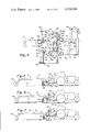
- FIG. 4 is a sectional view taken along lines 4--4 of FIG. 3;
- FIG. 5 is a side elevational view of the land leveling apparatus shown in FIGS. 1-4 on a flat or level grade plane with positions of the apparatus illustrated generally and some portions removed for clarity;
- FIG. 6 is a side elevational view of the apparatus shown in FIG. 5 with the rear wheels in a recess and the front wheels raised as they move over a hump;
- FIG. 7 is a side elevational view of the apparatus shown in FIG. 5 with the rear wheels raised to be on the hump;
- FIG. 8 is a front elevational view of a central portion of the land leveling attachment shown in FIGS. 1-7 with the side blade sections in the lowered working position and the lower hitch arms in the raised, non-hitch position;
- FIG. 9 is a front elevational view of the central portion of the land leveling attachment shown in FIG. 8 with the side sections in the raised inboard transport position;
- FIG. 10 is a rear elevational view of a lower level adjustment between the central and side blade sections with portions shown in section;
- FIG. 11 is a side elevational view of one of the lower hitch arms connected to the tractor linkage with a range of pivotal movement in the raised position shown in dashed lines;
- FIG. 12 is a sectional view taken along lines 12--12 of FIG. 11;
- FIG. 13 is an enlarged sectional view of the ball connector pivotally securing the rear end of each of the lower hitch arms to the central blade section;
- FIG. 14 is a side elevational view of one of the leveling frame wheels.
- FIG. 15 is a rear end view of one of the leveling frame wheels.
- a prime mover 9 in the form of a farm tractor to which is releasably hitched a land leveling implement or attachment 10 that is pulled by the tractor in a land leveling operation.
- the tractor 9 shown has a pair of front wheels 11, two pairs of rear wheels 12, and a rear axle housing 13.
- the hitching linkage shown attached to the rear axle housing 13 of the tractor 10 is a conventional arrangement for the releasable attachment of the tractor to a three-point hitch implement and is hydraulically powered by the hydraulic power equipment on the tractor.
- This three-point hitching linkage carried by the tractor includes an adjustable upper link 15 arranged along a longitudinal center line of the attachment and a pair of laterally spaced lower links 16 on opposite sides of a longitudinal center line of the attachment each articulated or pivotally connected to the rear axle 13 at its forward end and releasably connected to a crossbar 17 of a particular construction at its rear end.
- the pivotal connection of the upper link 15 to the rear axle housing 13 is referred to as the upper link point 18 and the pivotal connection of each of the lower links to the tractor is referred to as a lower link point 19.
- Each of the lower links is moved up and down relative to the lower link points 19 by means of a link 21 connected at one end to an intermediate position on lower link 16 at a pivot 22 and at the other end to a link 23 at a pivot 24.
- a two-way hydraulic cylinder 25 is connected to link 23 at a pivot 26 and to link 16 at a pivot 27.
- Cylinder 25 is coupled to the hydraulic system of the tractor to raise and lower the lower links relative to the lower link points 19 in response to hydraulic fluid being supplied to cylinder 25.
- the land leveling attachment 10 in general includes a blade assembly 28, a hitch assembly 29 secured to and extending forwardly of the blade assembly, and a leveling assembly 31 secured to and extending rearwardly of the blade assembly.
- the blade assembly 28 has a sectional scraping blade SB and includes a central blade section A which in turn has two articulated left and right side blade sections B anc C, respectively, pivotally connected at forward and rear pivots 32 and forward and rear pivots 33, respectively, these pivots being on the upper part at the opposite ends of the central blade section A.
- the side blade sections B and C pivot relative to the central blade section between a lowered working position (FIG. 2) in which the side blade sections extend laterally out from the ends of the central blade section and a raised inboard position (FIG. 1) in which they extend up from the ends of the central section.
- the central blade section A has a supporting frame including a tubular cross frame member 35 of square cross section with three laterally spaced knee frames 36 at an intermediate and end positions each connected to the back side of the cross frame member 35 and extending rearwardly and downwardly therefrom.
- An arcuate scraping blade member 39 is mounted in a depending manner from the underside of a horizontal portion of each of the knee frames and is affixed at the back to an upright portion of each of the knee frames and has a lower scraping edge 39a.
- An upper crossbar 41 and a lower crossbar 42 extend across the back of the upper and lower portions, respectively, of the blade and intermediate back braces 43 are provided between the knee frames along the back side for additional strength.
- Each of the side blade sections B and C is of an identical construction arranged for left and right side operation and is of a construction similar to the central blade section A.
- Each side blade section has a tubular cross frame member 45 of square cross section with knee frames 46, one at an intermediate position and another at an inner end position, and an outer end plate 49 that also forms a structural support like a third knee frame at the outer end.
- Each side section has an arcuate scraping blade member 51 aligned with scraping blade member 39 mounted in a depending manner affixed to the back of the knee frame 46, an upper crossbar 52, a lower crossbar 53, and back braces 54.
- Scraping blade members 51 and 39 arranged end-to-end in the working position form the composite scraping blade designated SB.
- Each linkage assembly 56 is connected between each side blade section B and C and the central blade section A which in general serves to lock the associated side section in the lowered working position and is responsive to the linear movement of a common two-way hydraulic actuator 58 to simultaneously raise and lower the side blade sections and to hold the side blade sections in the raised position.
- Each linkage assembly 56 includes a lever arm 59 fulcrumed at a pivot 61 between a front support plate 62 and rear support plate 63 that is secured to and projects up from the cross frame member 35.
- An adjustable line 64 has one end pivotally connected at pivot 65 to one end of the lever arm 59 and the other end is pivotally connected at a pivot 66 on a bracket plate 67 projecting up from the top of the associated side blade section.
- the adjustable link 64 and lever arm 59 are substantially end-to-end and substantially in line with the pivot 65 at a slight over-center position below a horizontal line passing through pivots at 61 and 66.
- This over-center arrangement locks the side blade sections in the lowered working position.
- a stop 68 is provided on the lever arm 59 against which the free end of the adjustable link 64 will abut to prevent the link 64 and lever arm 59 from going too far past the over-center position.
- the opposite ends of the two-way hydraulic actuating cylinder 58 are pivotally connected at a pivot 71 on each lever arm 59 opposite pivot 65 and offset to one side of a line passing through pivots 61 and 65 so that, as the actuating cylinder 58 is expanded to increase the effective length between the ends thereof, both lever arms 59 rotate or swing simultaneously from a generally laterally outwardly extending position to an upright position, which pulls the adjustable link 64 from a horizontal to an upwardly and inwardly inclined position forming an acute inside angle between the lever arm 59 and the associated link 64, causing the side blade sections B and C to pivot to the upright position about their respective pivots 32 and 33.
- the side sections B and C are then held in the upright or folded position by the pair of linkage assemblies 56 and hydraulic actuator 58 powered by the hydraulic system of the tractor.
- the lower level adjustment 76 includes an externally threaded member 78 affixed at one end to the central blade section A as by welds 79 and further by a bracket 81 secured to the knee frame 36 and to the threaded member at welds 82.
- the threaded member 78 projects laterally out and terminates in a narrowed stepped end portion 83 that is slidably inserted into an aperture in sleeve 84 affixed to the knee frame 46 of blade section B by welds at 85 and to a bracket 86 as by welds indicated at 87.
- An adjustment nut 88 threads on the end of the threaded member against the bracket 86 so that threading in one direction will raise the side blade section B slightly and in the other direction will lower the side blade section B slightly.
- a lock nut 89 threads on the threaded member 78 against nut 88 to lock the level adjustment at a particular setting.
- the lower level adjustment is normally set with the side blade section B level and does not require further adjustment.
- the upper level adjustment is provided by threading the adjustable links 64 in the linkage 56 used for raising and lowering the side blade sections, as above described.
- the hitch assembly 29 includes an upright mast plate 96 affixed to the front support plate 62 and further supported by an inclined brace 97 connected between mast plate 96 and knee frame 36.
- the mast plate 96 shown has two laterally spaced, parallel, forwardly projecting flanges 101 and 102 provided with three pairs of vertically spaced apertures 104, 105 and 106 each adapted to slidably receive an upper hitch pin defining a pivot 107.
- the rear end of the upper link 15 inserts between flanges 101 and 102 and has an aperture that aligns with a pair of aligned apertures in the mast plate flanges and the hitch pin 107 slide-fits in one of the three aligned apertures to pivotally and releasably connect the rear end of the upper link 15 to the mast plate 96 at a pivot 107.
- the hitch assembly 29 further includes two laterally spaced lower hitch arms 108 each pivotally connected at its rear end to the central blade section A at a side pivot connection.
- Each side pivot connection is of a universal-type joint with a ball connector 111 mounted on a lateral shaft 113 supported in a housing 115 affixed to blade section A.
- Each ball connector 111 is provided with an outer spherical race 111a inserted into and held in an aperture 119 in the rear end of arm 108 and an inner ball portion 111b movable in the race that is affixed to shaft 113 so that each hitch arm 108 rotates relative to blade section A about both a longitudinal axis and a lateral axis at its pivotal connection, providing for limited up and down movement and also twisting movement about a longitudinal axis of the tractor independently of the position of the blade sections.
- a single common center point pivotal connection may be used in place of the two side pivot connections wherein the rear ends of both hitch arms are secured to and pivot with a common crossbar pivoted at its center by an enlarged version of fixed center pivot pin 129 described hereinafter.
- Each housing 115 has a back wall portion 115a and a lower wall portion 115b on which the associated hitch arm 108 rests in a lowered position, as shown in dashed lines in FIG. 11.
- the housing 115 shown is constructed with an intermediate wall portion 115c providing a section for a category II hitch and a section for a category III hitch.
- each hitch arm 108 is secured against lateral movement during turns by a cross link 127.
- Cross link 127 is pivotally connected to pivot in a vertical plane at an inside end at a common center fixed pivot pin 129 on a bracket 131 affixed to the center frame member 35.
- Each cross link 127 is provided with a second aperture 133 to facilitate adjustment for a category II hitch.
- each cross link 127 is pivotally connected to an associated lower hitch arm 108 by a ball connector 132 having a pivot pin 134 connected to a bracket 136 secured to the inside of the hitch arm 108 between the front and rear ends of the hitch arm.
- No cross links 127 or associated structure is required for the center pivot hitch connection.
- Each hitch arm 108 is normally held in the upper position, shown in FIG. 11, during transport by a pin 141 on a bracket 142 and a pin 143 on front plate 62.
- the same link 144 with holes at the opposite ends preferably is used as that which releasably holds the crossbar 17 to the lower hitch arms 108.
- Each of the hitch arms 108 has a down-facing socket 151 at its front end that slidably receives an end portion of cross-bar 17 carried by the lower draft links 16 and 17 of the tractor.
- Each hitch arm 108 is of a bifurcated construction including a pair of laterally spaced arm plate portions 108a and 108b joined at their rear ends which carry the ball connector 111 and open at the front ends to slidably receive the rear end portion of a lower draft link 16.
- the two bifurcated plate portions 108a and 108b are each provided with a down-facing slot alined with one another having rounded corners to form the socket 151 at the front end that slidably receives the crossbar 17.
- the crossbar 17 is normally lowered under the sockets and raised into position by actuating cylinder 25.
- the plates are wider at the front end and have a notched area 158 at the rear that fits up against the frame member 35 in the raised transport position, as shown in dashed lines in FIG. 11.
- the link 144 with holes at each end is releasably supported across the slot opening on arm 108 by pins 161 and 162 to releasably fasten the crossbar to the lower hitch arms.
- the crossbar 17 has a lengthwise adjustment feature to facilitate its use with either a category II or a category III hitch.
- the hitch is shown in a category III setting.
- the adjustable crossbar 17 includes a central tubular member 164 in which end tubular members 165 and 166 are telescopically and slidably received. Adjustment bolts 167 and apertures in members 164, 165 and 166 facilitate the shortening of the effective length thereof.
- Each end tubular member has an external guide flange 168 that guides the crossbar into position between the plates 108a and 108b of the bifurcated lower hitch arms 108.
- Each end tubular member 166 carries an end shaft 171 with an external diameter that slides into a ball connector 172 in the lower link 16 and an end section 173 of reduced diameter that extends beyond the associated lower hitch arm 108.
- the crossbar 17 is shortened in length and the base connectors 111 are positioned in the inside sections of housing 115.
- the automatic leveling assembly 31 includes a generally open, box-shaped, leveling frame including two laterally spaced, parallel, hollow side members 175 on opposite sides of a longitudinal center line, a hollow front cross member 176, and a hollow rear cross member 177.
- Each side member has a downturned front end portion 178 pivotally connected to the rear outer end portion of cross frame member 35 at a pair of laterally spaced pivots 30 on opposite sides of a longitudinal center line of the attachment.
- the rear end of the leveling frame is supported for vehicular movement on a pair of laterally spaced wheels 181 mounted on end extensions of the rear cross member 177.
- each wheel 181 is carried by a caster bracket 182 with a stub shaft 183 rotated in a journal 184.
- the journal 184 is secured to the end extension of the cross member 177.
- the wheels are set on a selected caster designated by angle E and a camber designated by angle F in FIGS. 14 and 15 to avoid a digging in at the ends of the side blade sections during a turning movement.
- a preferred caster angle E is about three degrees and a preferred camber angle F is about one-half degree.
- the depth of the scraper blade may be selectively, manually adjusted by means of a four-sided or four-bar linkage arrangement including a link 188 connected at a pivot 189 to the cross member 176 having one end connected to one end of a two-way hydraulic cylinder 191 at a pivot 192.
- the other end of the cylinder 191 is connected at a pivot 193 to the mast plate 96.
- An adjustable link 194 is connected at a pivot 195 to the other end of link 188 and to the mast plate at a pivot 196 below pivot 193.
- Pivots 193 and 195 are positioned at spaced locations on the back side of the mast plate.
- the automatic level-adjusting assembly 31 hitched to the tractor as above described is shown to comprise an essentially four-sided or four-bar leveling linkage with opposite bars non-parallel to one another and with a pivot at each corner and functions to maintain the cutting blade assembly on a grade line designated P contacted by the front wheels 11 of the tractor and the trailing wheels 181 independently of the movement of the rear tractor wheels 12, as shown in FIGS. 5-7.
- This automatic leveling linkage is comprised of the upper link 15 pivotally connected to the tractor at pivot 18 and lower link 16 pivotally connected to the tractor at pivot 19, these links 15 and 16 being opposite and non-parallel to one another, as well as the rear axle housing 13 between pivots 18 and 19, and the rigid structure between pivots 107 and 113.
- pivots 113 and 107 The rigid structure between pivots 113 and 107 is one bar of the linkage that generally extends at a downward and rearward incline and is non-parallel to the opposite bar between pivots 18 and 19 that extends at a downward and forward incline.
- Pivot 107 is an upper rear control pivot and is adjustable up and down by virtue of the vertically spaced apertures in the mast plate.
- Pivot 113 is a lower rear pivot
- pivot 18 is an upper front pivot
- pivot 19 is a lower front pivot.
- this leveling linkage As the front wheels 11 move up over a hump and/or the rear wheels move down in a depression for an upward tilt of the tractor, the tractor pivots counterclockwise about pivot 19, pivot 18 moves rearwardly to push link 15 and control pivot 107 rearwardly and upwardly about pivot 113 with pivot 113 and leveling frame 31 raising and in turn raising and tilting the mast plate slightly forward and raising and tilting the scraping blade SB slightly forward so that the scraper blade edge remains in the grade line or plane contacted by the front wheels of the tractor and the rear wheels of the leveling frame, and soil in the blade SB fills the depression R.
- the automatic leveling assembly apparatus and operation may be further understood by considering the upper rear control pivot 107 as a common pivot at the apex of a bridge-like structure having one forwardly and downwardly inclined bridge portion extending from the pivot 107 along the tractor through approximately the front wheels of the tractor and another rearwardly and downwardly inclined bridge portion extending generally along the leveling frame from pivot 107 through the center of the rear wheels 181 with the scraping blade SB being supported in a depending manner from these bridge portions and moving up and down as the control pivot 107 moves up and down.
- the scraping blade is raised as shown in FIG. 6, the scraping blade is raised, and as the control pivot 107 is lowered as shown in FIG. 7 the scraping blade is lowered, but again at all times the triangulation of this bridge-like structure retains the scraping blade edge on a grade line or plane P contacted by the rear wheels 181 and front tractor wheels 11.
Landscapes
- Engineering & Computer Science (AREA)
- Mechanical Engineering (AREA)
- Mining & Mineral Resources (AREA)
- Civil Engineering (AREA)
- General Engineering & Computer Science (AREA)
- Structural Engineering (AREA)
- Agricultural Machines (AREA)
- Soil Working Implements (AREA)
Priority Applications (4)
| Application Number | Priority Date | Filing Date | Title |
|---|---|---|---|
| US05/869,852 US4236586A (en) | 1978-01-16 | 1978-01-16 | Land leveling apparatus with section blade assembly |
| CA313,410A CA1095237A (fr) | 1978-01-16 | 1978-10-13 | Appareil de nivelage |
| MX176200A MX147229A (es) | 1978-01-16 | 1979-01-05 | Mejoras en aparato para nivelar terrenos |
| MX19477079A MX156027A (es) | 1978-01-16 | 1979-01-05 | Mejoras a conjunto de enganche para un aparato nivelador de terremos como un tractor |
Applications Claiming Priority (1)
| Application Number | Priority Date | Filing Date | Title |
|---|---|---|---|
| US05/869,852 US4236586A (en) | 1978-01-16 | 1978-01-16 | Land leveling apparatus with section blade assembly |
Related Child Applications (1)
| Application Number | Title | Priority Date | Filing Date |
|---|---|---|---|
| US06/032,281 Division US4236587A (en) | 1979-04-23 | 1979-04-23 | Ground-working apparatus and hitch assembly therefor |
Publications (1)
| Publication Number | Publication Date |
|---|---|
| US4236586A true US4236586A (en) | 1980-12-02 |
Family
ID=25354375
Family Applications (1)
| Application Number | Title | Priority Date | Filing Date |
|---|---|---|---|
| US05/869,852 Expired - Lifetime US4236586A (en) | 1978-01-16 | 1978-01-16 | Land leveling apparatus with section blade assembly |
Country Status (3)
| Country | Link |
|---|---|
| US (1) | US4236586A (fr) |
| CA (1) | CA1095237A (fr) |
| MX (1) | MX147229A (fr) |
Cited By (12)
| Publication number | Priority date | Publication date | Assignee | Title |
|---|---|---|---|---|
| US4386662A (en) * | 1980-12-22 | 1983-06-07 | Aitan Kalif | Leveler frame attached to an agricultural tractor |
| US5213165A (en) * | 1991-11-18 | 1993-05-25 | Brandt Manufacturing Co., Inc. | Folding land plane |
| AT404370B (de) * | 1996-06-04 | 1998-11-25 | Beisteiner Peter | Vorrichtung zum planieren von anstehenden böden |
| US6021853A (en) * | 1998-12-14 | 2000-02-08 | Ralph H. Atkins | Field finishing land plane having retractable sections for road safety during towing |
| WO2003080943A1 (fr) * | 2002-03-25 | 2003-10-02 | Nicolaas Laurisse Sieling | Appareil de nivellement du sol |
| US20090200048A1 (en) * | 2008-02-11 | 2009-08-13 | Michael Frederick | Modified box scraper system and apparatus with implement for fine grading |
| US8083005B1 (en) | 2009-12-29 | 2011-12-27 | Nicolai Troy D | Land leveling device |
| RU2478757C2 (ru) * | 2011-06-10 | 2013-04-10 | Государственное образовательное учреждение высшего профессионального образования "Сибирская государственная автомобильно-дорожная академия (СибАДИ)" | Способ определения положения режущей кромки отвала автогрейдера |
| WO2013085762A1 (fr) * | 2011-12-09 | 2013-06-13 | Grossen Gary R | Machines agricoles |
| CN104372813A (zh) * | 2014-10-08 | 2015-02-25 | 华南农业大学 | 一种变幅宽可折叠式旱地平地机 |
| US9193233B2 (en) | 2013-03-15 | 2015-11-24 | Bruno Independent Living Aids, Inc. | Articulated hitch coupler |
| EP3255214A4 (fr) * | 2015-02-02 | 2018-02-14 | Daniel Villalba Hernández | Machine tractée pour le nivellement de sols et de chemins |
Families Citing this family (1)
| Publication number | Priority date | Publication date | Assignee | Title |
|---|---|---|---|---|
| CN113622472B (zh) | 2021-09-01 | 2022-08-12 | 江苏徐工工程机械研究院有限公司 | 回转架以及平地机 |
Citations (11)
| Publication number | Priority date | Publication date | Assignee | Title |
|---|---|---|---|---|
| US2478736A (en) * | 1948-08-04 | 1949-08-09 | Abram P Balzen | Vehicle coupling |
| US2583897A (en) * | 1950-07-03 | 1952-01-29 | Roy W Smeds | Automatic vineyard cultivator |
| US2697393A (en) * | 1953-01-02 | 1954-12-21 | Ferguson Harry Inc | Tractor hitch mechanism |
| US3032902A (en) * | 1960-10-03 | 1962-05-08 | Eversman Mfg Co | Tractor-mounted land leveler |
| US3090141A (en) * | 1961-05-12 | 1963-05-21 | Eversman Mfg Co | Land leveling attachment for tractors |
| US3428335A (en) * | 1967-03-08 | 1969-02-18 | David A Clark | Lift hitch assembly |
| US3524269A (en) * | 1967-09-15 | 1970-08-18 | Monarch Road Machinery Co | Mounting means for vehicular implements |
| US3967684A (en) * | 1974-08-01 | 1976-07-06 | Deere & Company | Wingfold positioning device |
| US4047574A (en) * | 1976-06-01 | 1977-09-13 | Foreman Calvin I | Implement for levelling levees |
| US4090725A (en) * | 1975-03-19 | 1978-05-23 | Ste Fiat France S.A. | Devices for automatically coupling implements to self-propelled vehicles |
| US4126328A (en) * | 1976-12-22 | 1978-11-21 | Massey-Ferguson Services N.V. | Hitches |
-
1978
- 1978-01-16 US US05/869,852 patent/US4236586A/en not_active Expired - Lifetime
- 1978-10-13 CA CA313,410A patent/CA1095237A/fr not_active Expired
-
1979
- 1979-01-05 MX MX176200A patent/MX147229A/es unknown
Patent Citations (11)
| Publication number | Priority date | Publication date | Assignee | Title |
|---|---|---|---|---|
| US2478736A (en) * | 1948-08-04 | 1949-08-09 | Abram P Balzen | Vehicle coupling |
| US2583897A (en) * | 1950-07-03 | 1952-01-29 | Roy W Smeds | Automatic vineyard cultivator |
| US2697393A (en) * | 1953-01-02 | 1954-12-21 | Ferguson Harry Inc | Tractor hitch mechanism |
| US3032902A (en) * | 1960-10-03 | 1962-05-08 | Eversman Mfg Co | Tractor-mounted land leveler |
| US3090141A (en) * | 1961-05-12 | 1963-05-21 | Eversman Mfg Co | Land leveling attachment for tractors |
| US3428335A (en) * | 1967-03-08 | 1969-02-18 | David A Clark | Lift hitch assembly |
| US3524269A (en) * | 1967-09-15 | 1970-08-18 | Monarch Road Machinery Co | Mounting means for vehicular implements |
| US3967684A (en) * | 1974-08-01 | 1976-07-06 | Deere & Company | Wingfold positioning device |
| US4090725A (en) * | 1975-03-19 | 1978-05-23 | Ste Fiat France S.A. | Devices for automatically coupling implements to self-propelled vehicles |
| US4047574A (en) * | 1976-06-01 | 1977-09-13 | Foreman Calvin I | Implement for levelling levees |
| US4126328A (en) * | 1976-12-22 | 1978-11-21 | Massey-Ferguson Services N.V. | Hitches |
Cited By (18)
| Publication number | Priority date | Publication date | Assignee | Title |
|---|---|---|---|---|
| US4386662A (en) * | 1980-12-22 | 1983-06-07 | Aitan Kalif | Leveler frame attached to an agricultural tractor |
| US5213165A (en) * | 1991-11-18 | 1993-05-25 | Brandt Manufacturing Co., Inc. | Folding land plane |
| AT404370B (de) * | 1996-06-04 | 1998-11-25 | Beisteiner Peter | Vorrichtung zum planieren von anstehenden böden |
| US6021853A (en) * | 1998-12-14 | 2000-02-08 | Ralph H. Atkins | Field finishing land plane having retractable sections for road safety during towing |
| WO2003080943A1 (fr) * | 2002-03-25 | 2003-10-02 | Nicolaas Laurisse Sieling | Appareil de nivellement du sol |
| US20050161238A1 (en) * | 2002-03-25 | 2005-07-28 | Sieling Nicolaas L. | Ground levelling apparatus |
| US7284621B2 (en) | 2002-03-25 | 2007-10-23 | Nicolaas Laurisse Sieling | Ground levelling apparatus |
| US20090200048A1 (en) * | 2008-02-11 | 2009-08-13 | Michael Frederick | Modified box scraper system and apparatus with implement for fine grading |
| US8083005B1 (en) | 2009-12-29 | 2011-12-27 | Nicolai Troy D | Land leveling device |
| RU2478757C2 (ru) * | 2011-06-10 | 2013-04-10 | Государственное образовательное учреждение высшего профессионального образования "Сибирская государственная автомобильно-дорожная академия (СибАДИ)" | Способ определения положения режущей кромки отвала автогрейдера |
| WO2013085762A1 (fr) * | 2011-12-09 | 2013-06-13 | Grossen Gary R | Machines agricoles |
| AU2012348208B2 (en) * | 2011-12-09 | 2016-11-03 | GK Machine, Inc. | Agricultural implements |
| US9193233B2 (en) | 2013-03-15 | 2015-11-24 | Bruno Independent Living Aids, Inc. | Articulated hitch coupler |
| US9844987B2 (en) | 2013-03-15 | 2017-12-19 | Bruno Independent Living Aids, Inc. | Articulated hitch coupler |
| US10576798B2 (en) | 2013-03-15 | 2020-03-03 | Bruno Independent Living Aids, Inc. | Articulated hitch coupler |
| CN104372813A (zh) * | 2014-10-08 | 2015-02-25 | 华南农业大学 | 一种变幅宽可折叠式旱地平地机 |
| CN104372813B (zh) * | 2014-10-08 | 2016-10-19 | 华南农业大学 | 一种变幅宽可折叠式旱地平地机 |
| EP3255214A4 (fr) * | 2015-02-02 | 2018-02-14 | Daniel Villalba Hernández | Machine tractée pour le nivellement de sols et de chemins |
Also Published As
| Publication number | Publication date |
|---|---|
| CA1095237A (fr) | 1981-02-10 |
| MX147229A (es) | 1982-10-26 |
Similar Documents
| Publication | Publication Date | Title |
|---|---|---|
| US5427185A (en) | Ditcher | |
| US5535832A (en) | Land leveler and cultivator | |
| US5113956A (en) | Forwardly folding tool bar | |
| US4898247A (en) | Earth scraper attachment for a tractor or the like | |
| US4576238A (en) | Folding outrigger attachment for farm implements | |
| US12012717B2 (en) | Earth working implement | |
| CA2260226C (fr) | Cadre pour engin pliant | |
| CA1281229C (fr) | Attelage pour le transport de machine agricole | |
| US4236586A (en) | Land leveling apparatus with section blade assembly | |
| US4700786A (en) | Drag-type road grader | |
| US4396069A (en) | Agricultural implement carriage system | |
| US3256942A (en) | Frame for agricultural implement having independently movable sections | |
| US6263977B1 (en) | Winged agricultural implement with headlands control system | |
| CA2132128C (fr) | Chassis pour cultivateur | |
| US4102404A (en) | Articulated cultivator | |
| US4402367A (en) | Folding tool beam and lift assembly | |
| US4236587A (en) | Ground-working apparatus and hitch assembly therefor | |
| US2968356A (en) | Telescopic beaming device | |
| US4301873A (en) | Agricultural implement having field and transport modes | |
| US3583495A (en) | Implements with tail wheel lift assists | |
| US3041751A (en) | Ditcher apparatus | |
| US4300640A (en) | Agricultural implement having field and transport modes | |
| CA1081022A (fr) | Accessoire agricole avec systeme de compensation des irregularites du terrain | |
| US4106568A (en) | Chisel plow with adjustable towing tongue and gauge wheels | |
| US4502545A (en) | Folding tool beam and lift assembly |
Legal Events
| Date | Code | Title | Description |
|---|---|---|---|
| AS | Assignment |
Owner name: EVERSMAN, INC., 1145 5TH STREET, DENVER, COLORADO Free format text: ASSIGNMENT OF ASSIGNORS INTEREST.;ASSIGNOR:EVERSMAN MFG. COMPANY, THE;REEL/FRAME:005140/0358 Effective date: 19890421 |
|
| AS | Assignment |
Owner name: ART S-WAY MANUFACTURING CO., INC., IOWA Free format text: ASSIGNMENT OF ASSIGNORS INTEREST.;ASSIGNOR:EVERSMAN, INC.;REEL/FRAME:005906/0881 Effective date: 19911018 |
|
| AS | Assignment |
Owner name: BANKAMERICA BUSINESS CREDIT, INC., ILLINOIS Free format text: SECURITY INTEREST;ASSIGNOR:ART S-WAY MANUFACTURING CO., INC.;REEL/FRAME:007629/0325 Effective date: 19950831 |