US4245439A - Element for prefabricated building and building obtained with such an element - Google Patents
Element for prefabricated building and building obtained with such an element Download PDFInfo
- Publication number
- US4245439A US4245439A US05/951,252 US95125278A US4245439A US 4245439 A US4245439 A US 4245439A US 95125278 A US95125278 A US 95125278A US 4245439 A US4245439 A US 4245439A
- Authority
- US
- United States
- Prior art keywords
- elements
- frame
- panel
- parallel relationship
- assembly
- Prior art date
- Legal status (The legal status is an assumption and is not a legal conclusion. Google has not performed a legal analysis and makes no representation as to the accuracy of the status listed.)
- Expired - Lifetime
Links
- 230000000712 assembly Effects 0.000 description 4
- 238000000429 assembly Methods 0.000 description 4
- 239000011449 brick Substances 0.000 description 1
- 239000000463 material Substances 0.000 description 1
- -1 tiles Substances 0.000 description 1
- 238000003466 welding Methods 0.000 description 1
Images




Classifications
-
- E—FIXED CONSTRUCTIONS
- E04—BUILDING
- E04B—GENERAL BUILDING CONSTRUCTIONS; WALLS, e.g. PARTITIONS; ROOFS; FLOORS; CEILINGS; INSULATION OR OTHER PROTECTION OF BUILDINGS
- E04B7/00—Roofs; Roof construction with regard to insulation
- E04B7/20—Roofs consisting of self-supporting slabs, e.g. able to be loaded
- E04B7/22—Roofs consisting of self-supporting slabs, e.g. able to be loaded the slabs having insulating properties, e.g. laminated with layers of insulating material
-
- E—FIXED CONSTRUCTIONS
- E04—BUILDING
- E04C—STRUCTURAL ELEMENTS; BUILDING MATERIALS
- E04C2/00—Building elements of relatively thin form for the construction of parts of buildings, e.g. sheet materials, slabs, or panels
- E04C2/30—Building elements of relatively thin form for the construction of parts of buildings, e.g. sheet materials, slabs, or panels characterised by the shape or structure
- E04C2/38—Building elements of relatively thin form for the construction of parts of buildings, e.g. sheet materials, slabs, or panels characterised by the shape or structure with attached ribs, flanges, or the like, e.g. framed panels
- E04C2/384—Building elements of relatively thin form for the construction of parts of buildings, e.g. sheet materials, slabs, or panels characterised by the shape or structure with attached ribs, flanges, or the like, e.g. framed panels with a metal frame
Definitions
- This invention has for object an element for prefabricated building.
- the known prefabricated elements for prefabricated buildings the invention pertains to and which will comprise all or part of the building structure as well as the various building walls have the drawback of being usable only for industrial buildings. Indeed to avoid damages during conveying, the visible walls of the elements are received within the thickness of the structure members bordering the elements to let same be stacked without any contacts between said walls. When the building is erected, the structural members remain visible and should it be desired to conceal same, there should be provided joints which project relative to said walls, which imparts to said building an unattractive appearance.
- the invention has for object to obviate this drawback and to provide prefabricated elements which allow to make building parts or buildings the walls of which are comprised of conventional materials, such as tiles, bricks, etc . . . . . and have no gap while allowing to conceal the structural members of the elements, said elements being so designed as to be completely manufactured and assembled in the works and to protect the wall associated therewith during the handling and conveying.
- said elements can comprise according to the invention, a complete from a building structure or from a building, said section being completely made and assembled in the works while having for the conveying a substantially parallelepiped shape of small size which is easy to handle and store and which can also be erected on the site with simple tooling and without trained workers.
- the element comprises at least one frame and at least one closing panel which extends between the inner edges of said frame, connecting means being provided betweeen the frame and the panel, said means being so arranged as to let the frame and panel move relative to one another, along a direction substantially in parallel relationship with the element thickness, to lie in two end positions, the one position in which the panel is received within the thickness of the frame and the other position in which the panel projects relative to said frame.
- said connecting means are so arranged as to fix in position the frame and the panel relative to one another, at least when same lie in both end positions thereof.
- the element is comprised of sections, each section comprising a frame and at least one closing panel, said sections being joined and hinged to one another to let same swing relative to one another about an axis in parallel relationship with one element edge, to fold the sections concertina-like on one another.
- the invention has also for object a building made by means of said elements.
- the building the size and shape of which may be selected by varying the number of elements which comprise same comprises joints to connect the closing panels, said joints being of the same kind as the panels to be connected, means being provided to fix in position said joints relative to the corresponding closing panels.
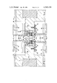
- FIG. 1 is a perspective view with parts broken away, of a prefabricated element according to the invention, the closing panel of which is shown in the position it lies in when conveying the element.
- FIG. 2 is a view similar to FIG. 1, the element closing panel being shown in that position it lies in when the element is set.
- FIGS. 3 and 4 are views similar to FIGS. 1 and 2, showing a variation in the element as shown in FIGS. 1 and 2.
- FIG. 5 is a cross-section view with parts broken away showing two elements according to the invention arranged side-by-side, said elements comprising a variation of the elements as shown in FIGS. 1 to 4, the frames of said elements being shown in solid lines in that position they lie in when conveying the elements, and in broken lines in that position they lie in when the elements are set in position.
- FIG. 6 is an elevation view with parts broken away, of an assembly of elements according to the invention which will comprise a building structure section, with a tile covering and a double-ceiling.
- FIG. 7 is a diagrammatic view in perspective showing the arrangement of four elements according to the invention which will comprise one end part of a four-sided building structure, said figure showing one element separately with the axes of those hinges allowing to fold back same for conveying, said element being shown in folded position, as well as one of the elements that form the double-ceiling and which are to be associated to said structure elements when erecting the building roof.
- FIG. 8 is a diagrammatic elevation view of a building made by means of element assemblies according to the invention, each assembly being so designated as to comprise a complete building section, namely walls, roof, ceiling or double-ceiling, the element being shown in erected position.
- FIG. 9 is a view similar to FIG. 8 with the assembly in the folded position.
- FIGS. 10 to 12 are views with parts broken away similar to FIGS. 8 and 9, showing variations of the assembly shown in FIGS. 8 and 9.
- FIG. 13 is a detailed cross-section view along line XIII--XIII in FIG. 6 showing the assembly of two elements shown in FIG. 6 as well as the joint connecting the closing panels of those elements which are to form the building roofing.
- Element 1 according to the invention and shown in FIGS. 1 and 2 comprises an undistortable frame 2 and a closing panel 3 which extends between edges 4 and 5 of the frame comprised of two U-shaped sections 6 which are assembled by means of braces 7.
- the closing panel 3 is associated with the frame 2 by connecting means 8 which are so arranged as to let the panel move substantially in parallel relationship with itself and said frame, to lie in two end positions, the one position (FIG. 1) in which the panel is received within the thickness of the frame for the handling, the storage and the conveying of element 1, and another position (FIG. 2) in which the panel projects relative to frame 2, that is the position it lies in when element 1 is associated with other elements for erecting a building.
- the element 1a as shown in FIGS. 3 and 4 comprises an undistortable frame 2 similar to the above-described frame but comprising two closing panels 3 and 3' arranged in parallel relationship within the frame, the connecting means 8 being so arranged as to let the panels 3 and 3' move relative to the frame 2 and in parallel relationship with one another along opposite directions.
- the panels as shown in FIG. 3, are received within the thickness of the frame for storing and conveying the element while as shown in FIG. 4, the panels each lie in a projecting position relative to the frame and thus comprise part of the inner and outer coverings of the building comprised of such elements.
- the connecting means 8 are for example comprised of two parallel stringers 9 made fast to the panels, said stringers in parallel relationship with the frame sections 6, being provided with tapped holes 10 with an axis at right angle to the panel movement direction, said holes being spaced regularly and located level with stud-holes 11 provided in the webs of sections 6 along a direction at right angle to the lengthwise direction of the stringers, screw-bolts 12 cooperating with holes 10 and stud-holes 11 in such a way that when said screw-bolts 12 are loosened, they let the panels move in parallel relationship with themselves and when said screw-bolts are tightened, they enable to fix the panels relative to the frame, in one or the other of said end positions.
- said elements may be provided an insulating element 70, not shown, which is fastened inside the frame in such a way as not to hamper the movements of the closing panel or panels, said panels may of course be provided with openings 19 and 20 and possibly with means 72 for closing same, associated with said closing panels.
- the elements 1b shown in FIG. 5 each comprise a frame 2 and a closing panel 3.
- the frame 2 is comprised of a first framework 44 formed by a U-shaped section 45 the flanges 46 of which face panel 3 and extend at right angle to the thickness thereof and a second framework 47 formed by an angle part 48 a flange 49 of which bears on web 50 of section 45, while the other flange 51 extends at right angle to the thickness of panel 3 and faces same.
- Panel 3 is provided along the edges thereof and opposite frame 2, with a projection 52 to which are made fast means 8 connecting panel 3 to frame 2, said connecting means 8 being comprised on the one hand, of an angle part 53 the flange 54 of which is fastened by screws 55, to projection 52 while the other flanges 56 bears on web 50 of section 45 opposite flange 49 of an angle part 48 and on the other hand by screw-bolts 57 the nut 58 of which is made fast by welding, to flange 56 of angle part 53 and the shaft 59 of which passes through openings 60 provided in flanges 49 and 56 of angle parts 48 and 53 as well as in web 50 of section 45.
- the projection 52 as well as the means 8 and said openings 60 are so arranged as to let flanges 46 and 51 of section 45 and angle part 48 be received on either side of projection 52, within the thickness of panel 3, when the elements are mounted and project on either side of panel 3 for the conveying of said elements.
- the frames 2 are covered by joints 61.
- the element assembly 1c as shown in FIG. 6 is comprised of four elements or parts or sections 13, 14, 15 and 16 in the shape of a quadrilateral with four right angles.
- Each part comprises a frame 2 and a closing panel 3, the end parts 13 and 16 being so designed as to form the structure and the double-ceiling of a building, while parts 14 and 15 comprise the roof structure and the roofing thereof.
- the part frames 2 are joined and hinged in 17, 18 and 19 to one another, in such a way that the parts may swing to be folded back on one another, concertina-like, for storing or conveying same, that is said parts are so hinged that in folded position, the outer surfaces 20 of the frames in parts 14 and 15 engage one another while the outer surfaces 21 of said frames in parts 14 and 15 engage the frames of parts 13 and 16, the size of the frames in the various parts, as considered in parallel relationship with the hinge axes, being the same while the size of the part frames as considered at right angle to the hinge axis, is the same by pair.
- the hinges 17 and 19 in FIG. 6, are staggered relative to the edges 22 of parts 14 and 15.
- FIGS. 6 and 13 show the assembly of parts together.
- a crown-post 26 joining hinge 18 to the ends 27 of parts 13 and 16.
- a joint 26' is arranged as shown in FIG. 12, between the element closing panels, said joint 26' due to the position of said panels relative to the frame, lying in the extension of said panels and concealing completely said frame.
- the hinges 17 and 19 could be located along the edges 22 of parts 14 and 15, the parts then being assembled endwise.
- elements 1 as shown in FIG. 6, in association with end elements 28, 29, 30 and 31 as shown in FIG. 7 or else when the building is of square shape, to use only elements as shown in said FIG. 7.
- Said latter elements are comprised of three parts hinged together to be foldable concertina-like for the conveying thereof, and which are each comprised of a frame with closing panel as described above.
- said end elements are supported by separate structure components which are arranged during the mounting and associated with prefabricated elements 35 which comprise the structure and the double-ceiling of the building, said elements 35 being comprised of two sections 36 and 37 hinged together in 38, the edges 39 of which are joined to the elements 28 and 29 while the edges 40 are joined to the elements 30 and 31.
- the element assembly 1d according to the invention and as shown in FIG. 8 to 11, comprises a complete section in a building.
- Said element thus comprises the walls, the roof as well as a floor or a double-ceiling.
- Said assemblies 1d comprise six parts, parts 13 and 16 which will form the building walls, parts 14 and 15 which will form the building roof and intermediate parts 42 and 43 which will comprise either a floor and the support thereof, or a double-ceiling and the support thereof.
- the intermediate parts 42 and 43 hinged in 44 and 45 on the parts 14 and 15, fit when the element lies in storage or conveying position, either as shown in FIGS. 8 and 9, within the parts 14 and 15 in such a way that the frames of parts 13 and 16 might bear on the frames of parts 14 and 15, or as shown in FIGS. 10 and 11, within parts 13 and 16, still in such a way that the frames thereof might bear on the frames of parts 14 and 15, the movable closing panels of the various parts being of course received in said part position, inside the part frames.
- element assembly 1c as shown in FIG. 6, to arrange the hinges in such a way that parts 13 and 16 fit within parts 14 and 15 when the element lies in the storage or conveying position thereof.
- the assemblies comprised of a plurality of parts comprise means so arranged as to lock the parts together when the element is erected.
- Said means may be comprised in the case of that element shown in FIG. 8, of the crown-post 26.
- Said means are also adjustable to allow from a particular element, varying the angle formed by parts 14 and 15 as well as the angle formed by each one of the parts 13 and 16 with the corresponding part 14 or 15.
- a frame 2 which would be comprised only of two parallel sections 6 between which are arranged said closing panel or panels with said connecting means 8 as described above, the stiffness of the frame-panel unit being provided when tightening the screw-bolts 12 of means 8 as the panel or panels lie in either end position thereof.
Landscapes
- Engineering & Computer Science (AREA)
- Architecture (AREA)
- Civil Engineering (AREA)
- Structural Engineering (AREA)
- Physics & Mathematics (AREA)
- Electromagnetism (AREA)
- Panels For Use In Building Construction (AREA)
- Conveying And Assembling Of Building Elements In Situ (AREA)
- Roof Covering Using Slabs Or Stiff Sheets (AREA)
- Building Environments (AREA)
Priority Applications (1)
| Application Number | Priority Date | Filing Date | Title |
|---|---|---|---|
| US06/186,343 US4314505A (en) | 1978-10-13 | 1980-09-11 | Rotary wheel type marking head |
Applications Claiming Priority (2)
| Application Number | Priority Date | Filing Date | Title |
|---|---|---|---|
| BE181691A BE859669A (fr) | 1977-10-13 | 1977-10-13 | Element pour batiment prefabrique et batiment realise a l'aide de cet element |
| BE181691 | 1977-10-13 |
Related Child Applications (1)
| Application Number | Title | Priority Date | Filing Date |
|---|---|---|---|
| US06/186,343 Continuation US4314505A (en) | 1978-10-13 | 1980-09-11 | Rotary wheel type marking head |
Publications (1)
| Publication Number | Publication Date |
|---|---|
| US4245439A true US4245439A (en) | 1981-01-20 |
Family
ID=3843050
Family Applications (1)
| Application Number | Title | Priority Date | Filing Date |
|---|---|---|---|
| US05/951,252 Expired - Lifetime US4245439A (en) | 1977-10-13 | 1978-10-13 | Element for prefabricated building and building obtained with such an element |
Country Status (7)
| Country | Link |
|---|---|
| US (1) | US4245439A (fr) |
| CA (1) | CA1107027A (fr) |
| CH (1) | CH630434A5 (fr) |
| DE (1) | DE2800769A1 (fr) |
| ES (1) | ES245518Y (fr) |
| GB (1) | GB2007283B (fr) |
| NL (1) | NL7810270A (fr) |
Cited By (5)
| Publication number | Priority date | Publication date | Assignee | Title |
|---|---|---|---|---|
| US4467573A (en) * | 1980-03-07 | 1984-08-28 | Kjessler & Mannerstrale Ab. | Container for an industry hall |
| RU2119029C1 (ru) * | 1997-08-21 | 1998-09-20 | Евгений Петрович Матвеев | Способ возведения мансардных этажей из объемных блоков |
| WO2000058579A1 (fr) * | 1999-03-16 | 2000-10-05 | Kaefer Isoliertechnik Gmbh & Co. Kg | Construction et son utilisation |
| KR100466695B1 (ko) * | 2001-08-10 | 2005-01-24 | (주)종현엔지니어링건축사사무소 | 조립식 건물의 지붕구조체와 벽체 간의 결합구조 및 방법 |
| US20080184651A1 (en) * | 2007-02-02 | 2008-08-07 | Bowman Jay J | Roof truss system |
Families Citing this family (1)
| Publication number | Priority date | Publication date | Assignee | Title |
|---|---|---|---|---|
| DE3440297A1 (de) * | 1984-11-05 | 1986-05-22 | Greschbach, Manfred, 7637 Ettenheim | Plattenfoermiges wandelement |
Citations (5)
| Publication number | Priority date | Publication date | Assignee | Title |
|---|---|---|---|---|
| GB142128A (en) * | 1918-07-25 | 1921-05-05 | Lioubicha Praportchetovitch | Improvements in or relating to collapsible folding huts |
| US2499790A (en) * | 1947-09-16 | 1950-03-07 | Wilbert P E Smith | Portable bathhouse |
| DE802594C (de) * | 1948-10-02 | 1951-02-15 | Gutehoffnungshuette Oberhausen | Behelfsheim, Scheune o. dgl. Gebaeude in Stahlbauausfuehrung |
| FR1385350A (fr) * | 1963-03-22 | 1965-01-08 | Perfectionnements apportés aux charpentes de toitures | |
| US3485346A (en) * | 1967-05-08 | 1969-12-23 | Charles M Ballard | Hinged roof structure |
Family Cites Families (8)
| Publication number | Priority date | Publication date | Assignee | Title |
|---|---|---|---|---|
| DE906505C (de) * | 1951-09-28 | 1954-03-15 | Jacques Ogg & Soehne | Satteldach-Kleinbau |
| DE1828214U (de) * | 1961-01-05 | 1961-03-16 | Walter Schulz | Aus rahmen und fuellung bestehende fertigwand, insbesondere fuer wetterschutzhallen u. dgl. |
| DE1841099U (de) * | 1961-07-24 | 1961-11-09 | Neue Heimat Gemeinnuetzige Woh | Zement- oder magnesitgebundene holzfaserplatte. |
| DE1868835U (de) * | 1962-12-17 | 1963-03-14 | Gertrud Schrettenbrunner | Montagefertige grossplattenwand. |
| US3557500A (en) * | 1968-07-26 | 1971-01-26 | Structex Corp | Foldable structure |
| GB1402359A (en) * | 1971-12-29 | 1975-08-06 | Misawa Homes Co | Prefabricated buildings |
| DK140222B (da) * | 1974-02-20 | 1979-07-09 | Joergen Skoubo Johansen | Hus- eller tagkonstruktion. |
| DE2549938A1 (de) * | 1975-11-07 | 1977-05-18 | Georg Hegger | Katastrophenbox |
-
1978
- 1978-01-09 DE DE19782800769 patent/DE2800769A1/de not_active Ceased
- 1978-10-12 NL NL7810270A patent/NL7810270A/xx not_active Application Discontinuation
- 1978-10-13 ES ES1978245518U patent/ES245518Y/es not_active Expired
- 1978-10-13 CH CH1066778A patent/CH630434A5/fr not_active IP Right Cessation
- 1978-10-13 GB GB7840523A patent/GB2007283B/en not_active Expired
- 1978-10-13 CA CA313,393A patent/CA1107027A/fr not_active Expired
- 1978-10-13 US US05/951,252 patent/US4245439A/en not_active Expired - Lifetime
Patent Citations (5)
| Publication number | Priority date | Publication date | Assignee | Title |
|---|---|---|---|---|
| GB142128A (en) * | 1918-07-25 | 1921-05-05 | Lioubicha Praportchetovitch | Improvements in or relating to collapsible folding huts |
| US2499790A (en) * | 1947-09-16 | 1950-03-07 | Wilbert P E Smith | Portable bathhouse |
| DE802594C (de) * | 1948-10-02 | 1951-02-15 | Gutehoffnungshuette Oberhausen | Behelfsheim, Scheune o. dgl. Gebaeude in Stahlbauausfuehrung |
| FR1385350A (fr) * | 1963-03-22 | 1965-01-08 | Perfectionnements apportés aux charpentes de toitures | |
| US3485346A (en) * | 1967-05-08 | 1969-12-23 | Charles M Ballard | Hinged roof structure |
Cited By (6)
| Publication number | Priority date | Publication date | Assignee | Title |
|---|---|---|---|---|
| US4467573A (en) * | 1980-03-07 | 1984-08-28 | Kjessler & Mannerstrale Ab. | Container for an industry hall |
| RU2119029C1 (ru) * | 1997-08-21 | 1998-09-20 | Евгений Петрович Матвеев | Способ возведения мансардных этажей из объемных блоков |
| WO2000058579A1 (fr) * | 1999-03-16 | 2000-10-05 | Kaefer Isoliertechnik Gmbh & Co. Kg | Construction et son utilisation |
| KR100466695B1 (ko) * | 2001-08-10 | 2005-01-24 | (주)종현엔지니어링건축사사무소 | 조립식 건물의 지붕구조체와 벽체 간의 결합구조 및 방법 |
| US20080184651A1 (en) * | 2007-02-02 | 2008-08-07 | Bowman Jay J | Roof truss system |
| US7677009B2 (en) * | 2007-02-02 | 2010-03-16 | Nova Chemicals Inc. | Roof truss system |
Also Published As
| Publication number | Publication date |
|---|---|
| GB2007283A (en) | 1979-05-16 |
| ES245518Y (es) | 1980-12-16 |
| CH630434A5 (fr) | 1982-06-15 |
| NL7810270A (nl) | 1979-04-18 |
| GB2007283B (en) | 1982-04-28 |
| CA1107027A (fr) | 1981-08-18 |
| ES245518U (es) | 1980-06-16 |
| DE2800769A1 (de) | 1979-04-19 |
Similar Documents
| Publication | Publication Date | Title |
|---|---|---|
| US4644708A (en) | Prefabricated modular building element and a building comprising such elements | |
| US4894974A (en) | Structural interlock frame system | |
| US4267682A (en) | Building panel | |
| US3738083A (en) | Prefabricated house | |
| CA2032640A1 (fr) | Coffrage prefabrique | |
| US4346540A (en) | Device relating to building frameworks | |
| US3992828A (en) | Collapsible prefabricated house | |
| US3474582A (en) | Building system | |
| US4245439A (en) | Element for prefabricated building and building obtained with such an element | |
| US4115969A (en) | Building panel and wall | |
| US4003167A (en) | Cabin construction | |
| WO1990003475A1 (fr) | Batiment prefabrique | |
| JP2587646B2 (ja) | 移動建物 | |
| JPS5834625B2 (ja) | 家屋における躯体組立用部材 | |
| JP3269936B2 (ja) | ユニット建物 | |
| US5331780A (en) | Hyperbolic paraboloid roof and sidewall system | |
| KR100391111B1 (ko) | 이동조립식 건축물 | |
| JP3448397B2 (ja) | ユニット建物 | |
| IE45787B1 (en) | Improvements in or relating to a tolerance adjustment device for wall panels | |
| JP2995002B2 (ja) | 母屋支持構造 | |
| PL210230B1 (pl) | Naroże ścian budynku | |
| JP3255496B2 (ja) | 上下階用建物ユニットの連結方法 | |
| JP3027711B2 (ja) | 妻壁パネル | |
| JP3526333B2 (ja) | ロング土台使用建物骨組構造 | |
| JPS59368Y2 (ja) | 構築物の組立ユニット |