US4251090A - Safety ski binding - Google Patents
Safety ski binding Download PDFInfo
- Publication number
- US4251090A US4251090A US06/001,364 US136479A US4251090A US 4251090 A US4251090 A US 4251090A US 136479 A US136479 A US 136479A US 4251090 A US4251090 A US 4251090A
- Authority
- US
- United States
- Prior art keywords
- ski
- sole plate
- pivotal support
- support part
- centering
- Prior art date
- Legal status (The legal status is an assumption and is not a legal conclusion. Google has not performed a legal analysis and makes no representation as to the accuracy of the status listed.)
- Expired - Lifetime
Links
Images

Classifications
-
- A—HUMAN NECESSITIES
- A63—SPORTS; GAMES; AMUSEMENTS
- A63C—SKATES; SKIS; ROLLER SKATES; DESIGN OR LAYOUT OF COURTS, RINKS OR THE LIKE
- A63C9/00—Ski bindings
- A63C9/001—Anti-friction devices
-
- A—HUMAN NECESSITIES
- A63—SPORTS; GAMES; AMUSEMENTS
- A63C—SKATES; SKIS; ROLLER SKATES; DESIGN OR LAYOUT OF COURTS, RINKS OR THE LIKE
- A63C9/00—Ski bindings
-
- A—HUMAN NECESSITIES
- A63—SPORTS; GAMES; AMUSEMENTS
- A63C—SKATES; SKIS; ROLLER SKATES; DESIGN OR LAYOUT OF COURTS, RINKS OR THE LIKE
- A63C9/00—Ski bindings
- A63C9/007—Systems preventing accumulation of forces on the binding when the ski is bending
-
- A—HUMAN NECESSITIES
- A63—SPORTS; GAMES; AMUSEMENTS
- A63C—SKATES; SKIS; ROLLER SKATES; DESIGN OR LAYOUT OF COURTS, RINKS OR THE LIKE
- A63C9/00—Ski bindings
- A63C9/08—Ski bindings yieldable or self-releasing in the event of an accident, i.e. safety bindings
- A63C9/081—Ski bindings yieldable or self-releasing in the event of an accident, i.e. safety bindings with swivel sole-plate
-
- A—HUMAN NECESSITIES
- A63—SPORTS; GAMES; AMUSEMENTS
- A63C—SKATES; SKIS; ROLLER SKATES; DESIGN OR LAYOUT OF COURTS, RINKS OR THE LIKE
- A63C9/00—Ski bindings
- A63C9/08—Ski bindings yieldable or self-releasing in the event of an accident, i.e. safety bindings
- A63C9/084—Ski bindings yieldable or self-releasing in the event of an accident, i.e. safety bindings with heel hold-downs, e.g. swingable
- A63C9/0841—Ski bindings yieldable or self-releasing in the event of an accident, i.e. safety bindings with heel hold-downs, e.g. swingable with a single jaw
Definitions
- a safety ski binding comprising a sole plate for receiving a ski boot, which sole plate engages with each of its two ends a ski-fixed holding part, is held against rotation by a spring-loaded locking mechanism, and is rotatably supported approximately in its center about a ski-fixed, vertical pivotal support part and is simultaneously secured also against release from said ski.
- a rotatably supported sole plate of the above-mentioned type is described for example in German OS No. 2 324 078.
- the sole plate consists of a base plate on the ski and a plate on the boot side.
- the space between the plates is protected against external influences by an expandable sleeve.
- the connection between the two plates is created by a bearing, the vertical pivot axis of which extends through the shin-bone axis and the horizontal pivot axis of which extends transversely with respect to the longitudinal axis of the ski in a plane of the vertical axis.
- the vertical support is constructed as a ball bearing for reducing friction
- the horizontal support consists of a sliding bearing made of bolts and tetrapolyethylene fluoride sleeves.
- the foregoing described construction of the known apparatus permits at the same time to recognize the first disadvantage of this solution, namely, the use of many structural parts and the plate also has to have a special design.
- the use of many structural parts is not only expensive, also the number of tolerance errors increase and the frictional forces which are to be overcome increase.
- a further disadvantage consists in the structural parts which determine the position of the vertical pivotal support part not permitting any play for receiving of compression forces, which are created by a bending of the ski, for example during travel over a depression. Furthermore it is absolutely necessary that the plate be permitted to pivot about an additional horizontal axis.
- This construction again has a disadvantage namely the bent areas are created automatically in the slot areas where the material thickness is the least with reference ot the width of the plate and thus breakage of the plate can easily occur.
- the tapered points serve as rests for the entire weight of the skier, since the ski supports the plate along these tapered portions.
- Similar situations also exist when the grooves are provided extending inwardly from the two sides and the connection is formed by connecting pieces which exist centrally with respect to the longitudinal axis of the ski.
- the objects of the invention are to avoid the aforementioned problems and further disadvantages of the known constructions and to provide a sole plate of the above-mentioned type as insensitive as possible also with respect to a bending of the ski. Since furthermore each screw hole in a ski weakens the ski, it is possible to secure the sole plate or its two holding parts to the upper side of the ski with as few screws as possible.
- the set objects are inventively attained by the pivot part and the two ski-fixed holding parts of the sole plate being screwed to the ski each with only one screw arranged on longitudinal axis of the ski, and the individual holding parts are each fixedly connected to one centering plate, which centering plates permit a reciprocal shifting upon a bending of the ski by the provision of one elongated hole in each centering plate and which is associated with the pivot part and forms together with the pivot part an enlarged head received in a blind hole of the sole plate, which opens upwardly and limits the vertical movement of the ski relative to the sole plate.
- the two-part construction of the centering mechanism enables a deformation-free compensation for a change in length of the ski occurring during a bending thereof.
- the pivotal support part and the blind hole are thereby inventively constructed so that they permit the sole plate to be positioned during bending of the ski on a chord with respect to an arc defined by the ski.
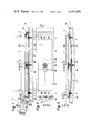
- FIG. 1 is a side view of the inventive sole plate, the spring-loaded locking mechanism and the angular holding profile, partially sectioned along the line I--I of FIG. 2;
- FIG. 2 is a top view of FIG. 1 with a common centering mechanism for the locking parts and omitting the sole plate;
- FIG. 3 illustrates in cross section the position of the sole plate and the remaining structural parts during a bending of the ski, otherwise approximately according to FIG. 1;
- FIG. 4 illustrates in cross section front and rear holding parts constructed in one piece with the respective front and rear centering plates.
- FIG. 1 illustrates a sole plate 2 which is pivotally mounted on a partially illustrated ski 1, which has a locking mechanism 6 at its rear end and a profiled holding piece 10 at its front end.
- the sole plate 2 which is designed substantially rectangularly in shape has over its length which extends parallel with respect to the upper side of the ski a uniform thickness and, approximately in the center of the sole plate 2, there is provided on the upper side 2a thereof an upwardly opening blind hole 2b.
- An opening 2c concentric with the opening 2b is provided in the bottom of the blind hole 2b, the diameter of which is approximately half the size of the diameter of the blind hole 2b.
- the opening 2c receives a pivotal support part 3 therein.
- the axis of the pivotal support part 3 which extends perpendicularly to the upper surface 1a of the ski has a flat enlarged head 3a at its end remote from the ski 1.
- the pivotal support part 3 is designed so that the upper surface of the head 3a is generally flush with the upper surface 2a of the sole plate in the normal position of use (downhill skiing position) thereof, namely when the ski 1 is not deformed by an external force applied thereto.
- the diameter of the pivotal support part 3 and of its flat head 3a are designed slightly smaller than the diameter of the opening 2c or of the blind hole 2b, in order to permit a relative movement between the pivotal support part 3 and the sole plate 2, which movement will be yet described more in detail hereinbelow.
- the pivotal support part 3 has an opening therethrough which is concentric with respect to the longitudinal axis of the pivotal support part, which opening has a countersunk surface at the end remote from the ski 1, in order to be able to receive therein a flat-head screw 3b which is connected to the ski.
- the sole plate 2 rests with its ends on a front sole plate holding part 5 and a rear sole plate holding part 6a.
- Each sole plate holding part 5, 6a is appropriately positioned by the interpositioning of a centering device 8, 9 on the upper surface 1a of the ski 1.
- the centering device is composed of a front centering plate 8 and a rear centering plate 9.
- rivets 4 connect the centering plate 8 to the front sole plate holding part 5 and the centering plate 9 to the rear sole plate holding part 6a.
- the rear sole plate holding part 6a has two bent sections 6b and 6c. The bent section 6b extends upwardly and rearwardly from the rear sole plate holding part 6a.
- the lateral edge of the first bent section 6b of the rear sole plate holding part 6a converge in the upward direction toward the second bent section 6c which extends generally horizontally.
- the bent section 6b has an opening 6d approximately in its center, which opening serves to receive a mushroomlike locking element of the spring-loaded locking mechanism 6. The release operations are controlled by this locking mechansim during twisting falls and partially during falls wherein the binding is subjected to simultaneously applied upward and sideward forces.
- the outline of the rear edge of the second bent section 6c of the rear sole plate holding part 6a is circularly constructed.
- the rear sole plate holding part 6a extends upwardly in the region of its two bent sections 6b, 6c to a height wherein the upper surface of the bent section 6c is approximately twice the thickness of the plate 2.
- the front sole plate holding part 5 which is connected to the centering plate 8 by means of rivets 4 has a doubly bent member generally defining an S-shaped member.
- the front edge of the front sole plate holding part 5 is provided with a radius which is as large as the spacing between the holding part 5 and the central axis of the pivotal support part 3, so that in spite of an interfitting relation, it is assured that the angled holding profile 10 which grips over the holding part 5 and is fixedly connected to the plate 2 will pivot with the sole plate about the axis of the pivotal support part 3.
- the sole plate holding part 5 has an overall height which is approximately twice the thickness of the material thereof. Both sole plate holding parts 5, 6a are designed as wide as the plate 2.
- the centering plates 8 and 9 are used for centering.
- the screws 7 are received in the aligned openings in the centering plates 8 and 9 and on the central longitudinal axis of the ski and in the sole plate holding parts 5, 6a.
- Each of the two centering plates 8, 9 is designed longer than half of the total length of the plate 2.
- the centering plates are riveted to the sole plate holding parts 5, 6a so that the longitudinal ends thereof project beyond the ends of the sole plate holding parts 5, 6a.
- the other ends of each of the centering plates 8, 9 project slightly beyond the region of the pivotal support part 3 and overlap.
- the centering plate 9 is bent twice, approximately at a right angle in both places and overlaps part of the centering plate 8.
- each centering plate 8, 9 has an elongated hole 8a and 9a, respectively, which extends parallel to the longitudinal axis of the ski.
- the elongated hole 8a is provided in the front centering plate 8 and the elongated hole 9a is provided in the rear centering plate 9.
- the two elongated holes 8a, 9a are constructed in the associated centering plates 8, 9 so that the pivotal support part 3 almost engages in the normal position of use according to FIGS. 1 and 2 (downhill skiing position) of the mutually adjacent ends of the two elongated holes 8a, 9a.
- FIG. 3 illustrates the ski during an externally applied force causing the ski to flex.
- the ski is bent such that the centering plates 8 and 9 define a chord of the arced ski 1.
- the centering plates 8 and 9 are thus both moved in direction toward the pivotal support part 3. This movement is made possible only through the two, already more in detail described elongated holes 8a and 9a.
- the sole plate 2 forms, as stated above, the chord for an arc described by the ski.
- the sole plate 2 is secured against loss by the enlarged head 3a of the pivotal support part 3, which permits the sole plate 2 to be lifted from the ski 1 at least in the region of its longitudinal center and permits a compensation of the bending of the ski 1, until the bottom of the blind hole 2b engages the lower surface of the enlarged head 3a of the pivotal support part 3.
- the invention is not limited to the illustrated exemplary embodiment. Various modifications are conceivable, which lie by all means within the scope of the invention.
- at least one or both of the centering plates can consist of a thin sheet material and are superposed in the region of the pivotal support part.
Landscapes
- Connection Of Plates (AREA)
- Footwear And Its Accessory, Manufacturing Method And Apparatuses (AREA)
- Drilling And Exploitation, And Mining Machines And Methods (AREA)
- Perforating, Stamping-Out Or Severing By Means Other Than Cutting (AREA)
Applications Claiming Priority (2)
| Application Number | Priority Date | Filing Date | Title |
|---|---|---|---|
| AT72/78 | 1978-01-05 | ||
| AT7278A AT357077B (de) | 1978-01-05 | 1978-01-05 | Sicherheitsskibindung |
Publications (1)
| Publication Number | Publication Date |
|---|---|
| US4251090A true US4251090A (en) | 1981-02-17 |
Family
ID=3480786
Family Applications (1)
| Application Number | Title | Priority Date | Filing Date |
|---|---|---|---|
| US06/001,364 Expired - Lifetime US4251090A (en) | 1978-01-05 | 1979-01-05 | Safety ski binding |
Country Status (6)
| Country | Link |
|---|---|
| US (1) | US4251090A (de) |
| JP (1) | JPS5555798A (de) |
| AT (1) | AT357077B (de) |
| AU (1) | AU5157079A (de) |
| CA (1) | CA1106414A (de) |
| DE (1) | DE2900240A1 (de) |
Cited By (7)
| Publication number | Priority date | Publication date | Assignee | Title |
|---|---|---|---|---|
| US4573701A (en) * | 1983-01-21 | 1986-03-04 | Tmc Corporation | Release ski binding |
| US4616843A (en) * | 1983-12-19 | 1986-10-14 | Tmc Corporation | Release ski binding |
| US5149123A (en) * | 1989-02-22 | 1992-09-22 | Varpat Patentverwertungs Ag | Ski binding with front and heel jaws connected by a carrier plate for the sole |
| US20030047910A1 (en) * | 2001-10-02 | 2003-03-13 | Eugene Golling | Apparatus for gliding over snow |
| US6616151B1 (en) * | 2001-10-02 | 2003-09-09 | Eugene Golling | Apparatus for gliding over snow |
| US9526971B1 (en) | 2015-09-18 | 2016-12-27 | Rossland Binding Company | Remote release ski binding |
| US10729968B2 (en) | 2018-05-25 | 2020-08-04 | Rossland Binding Company | Remote release snowboard binding |
Families Citing this family (4)
| Publication number | Priority date | Publication date | Assignee | Title |
|---|---|---|---|---|
| AT357079B (de) * | 1978-02-23 | 1980-06-10 | Tyrolia Freizeitgeraete | Sicherheitsskibindung |
| FR2654358B1 (fr) * | 1989-11-13 | 1992-02-28 | Rossignol Sa | Fixation de securite a plaque. |
| AT402900B (de) * | 1990-12-21 | 1997-09-25 | Varpat Patentverwertung | Kupplungsvorrichtung zwischen schi und schischuh mit einer längenverstellvorrichtung |
| FR2699418B1 (fr) * | 1992-12-17 | 1995-03-10 | Salomon Sa | Dispositif interface entre un ski et des éléments de fixation. |
Citations (7)
| Publication number | Priority date | Publication date | Assignee | Title |
|---|---|---|---|---|
| AT299030B (de) | 1970-09-28 | 1972-06-12 | Smolka & Co Wiener Metall | Sohlenplatte |
| US3813109A (en) * | 1971-03-18 | 1974-05-28 | Salomon Georges P J | Device for securing a boot to a ski |
| AT326015B (de) | 1973-02-21 | 1975-11-25 | Marker Hannes | Sicherheits-skibindung |
| AT330632B (de) | 1974-07-26 | 1976-07-12 | Smolka & Co Wiener Metall | Sicherheitsskibindung |
| US4095814A (en) * | 1975-09-24 | 1978-06-20 | Tmc Corporation | Heel holder |
| US4098522A (en) * | 1975-01-28 | 1978-07-04 | Jean Joseph Alfred Beyl | Safety ski binding |
| DE2324078C3 (de) | 1973-05-12 | 1980-09-04 | Vereinigte Baubeschlagfabriken Gretsch & Co Gmbh, 7250 Leonberg |
-
1978
- 1978-01-05 AT AT7278A patent/AT357077B/de not_active IP Right Cessation
-
1979
- 1979-01-04 DE DE19792900240 patent/DE2900240A1/de not_active Withdrawn
- 1979-01-05 US US06/001,364 patent/US4251090A/en not_active Expired - Lifetime
- 1979-09-24 CA CA336,191A patent/CA1106414A/en not_active Expired
- 1979-10-02 JP JP12722979A patent/JPS5555798A/ja active Pending
- 1979-10-08 AU AU51570/79A patent/AU5157079A/en not_active Abandoned
Patent Citations (9)
| Publication number | Priority date | Publication date | Assignee | Title |
|---|---|---|---|---|
| AT299030B (de) | 1970-09-28 | 1972-06-12 | Smolka & Co Wiener Metall | Sohlenplatte |
| US3797844A (en) * | 1970-09-28 | 1974-03-19 | Gertsch Ag | Ski binding |
| US3797839A (en) * | 1970-09-28 | 1974-03-19 | Gertsch Ag | Ski binding |
| US3813109A (en) * | 1971-03-18 | 1974-05-28 | Salomon Georges P J | Device for securing a boot to a ski |
| AT326015B (de) | 1973-02-21 | 1975-11-25 | Marker Hannes | Sicherheits-skibindung |
| DE2324078C3 (de) | 1973-05-12 | 1980-09-04 | Vereinigte Baubeschlagfabriken Gretsch & Co Gmbh, 7250 Leonberg | |
| AT330632B (de) | 1974-07-26 | 1976-07-12 | Smolka & Co Wiener Metall | Sicherheitsskibindung |
| US4098522A (en) * | 1975-01-28 | 1978-07-04 | Jean Joseph Alfred Beyl | Safety ski binding |
| US4095814A (en) * | 1975-09-24 | 1978-06-20 | Tmc Corporation | Heel holder |
Cited By (8)
| Publication number | Priority date | Publication date | Assignee | Title |
|---|---|---|---|---|
| US4573701A (en) * | 1983-01-21 | 1986-03-04 | Tmc Corporation | Release ski binding |
| US4616843A (en) * | 1983-12-19 | 1986-10-14 | Tmc Corporation | Release ski binding |
| US5149123A (en) * | 1989-02-22 | 1992-09-22 | Varpat Patentverwertungs Ag | Ski binding with front and heel jaws connected by a carrier plate for the sole |
| US20030047910A1 (en) * | 2001-10-02 | 2003-03-13 | Eugene Golling | Apparatus for gliding over snow |
| US6616151B1 (en) * | 2001-10-02 | 2003-09-09 | Eugene Golling | Apparatus for gliding over snow |
| US6983952B2 (en) * | 2001-10-02 | 2006-01-10 | Eugene Golling | Apparatus for gliding over snow |
| US9526971B1 (en) | 2015-09-18 | 2016-12-27 | Rossland Binding Company | Remote release ski binding |
| US10729968B2 (en) | 2018-05-25 | 2020-08-04 | Rossland Binding Company | Remote release snowboard binding |
Also Published As
| Publication number | Publication date |
|---|---|
| CA1106414A (en) | 1981-08-04 |
| ATA7278A (de) | 1979-10-15 |
| JPS5555798A (en) | 1980-04-23 |
| DE2900240A1 (de) | 1979-07-12 |
| AU5157079A (en) | 1980-04-17 |
| AT357077B (de) | 1979-10-15 |
Similar Documents
| Publication | Publication Date | Title |
|---|---|---|
| US3955825A (en) | Holding mechanism for ski boots | |
| US4660849A (en) | Toe piece for a safety ski-binding | |
| US4266806A (en) | Safety ski binding | |
| US4893831A (en) | Safety ski binding | |
| US4147378A (en) | Device for use with a ski binding | |
| JPH04212389A (ja) | スキー板にスキー靴を取り付ける装置 | |
| US4524990A (en) | Adjusting mechanism | |
| US4352507A (en) | Sole-support mechanism | |
| US4600213A (en) | Safety ski-binding having a sole plate | |
| US3544123A (en) | Anti-friction device for ski boots and skis | |
| US20070205583A1 (en) | Interface device for a gliding board | |
| US7100938B2 (en) | Disengageable ski binding | |
| US4134603A (en) | Safety ski binding | |
| US4371187A (en) | Ski brake | |
| US4262924A (en) | Hinge ski | |
| US5282642A (en) | Apparatus for biasing | |
| US4795185A (en) | Heel piece for safety ski binding | |
| US2338249A (en) | Disuniting ski bindings | |
| US5149124A (en) | Front jaw | |
| US4890855A (en) | Releasable ski stop | |
| US3930661A (en) | Safety ski-binding | |
| US4333667A (en) | Ski brake | |
| US4533155A (en) | Safety ski binding | |
| US4269431A (en) | Safety ski binding | |
| US3954277A (en) | Ski binding |