US4274803A - High-pressure centrifugal pump unit - Google Patents
High-pressure centrifugal pump unit Download PDFInfo
- Publication number
- US4274803A US4274803A US06/037,022 US3702279A US4274803A US 4274803 A US4274803 A US 4274803A US 3702279 A US3702279 A US 3702279A US 4274803 A US4274803 A US 4274803A
- Authority
- US
- United States
- Prior art keywords
- speed
- prime mover
- stage
- housing
- operative
- Prior art date
- Legal status (The legal status is an assumption and is not a legal conclusion. Google has not performed a legal analysis and makes no representation as to the accuracy of the status listed.)
- Expired - Lifetime
Links
- 239000007787 solid Substances 0.000 claims description 6
- 230000005540 biological transmission Effects 0.000 description 10
- 238000004519 manufacturing process Methods 0.000 description 5
- 238000010276 construction Methods 0.000 description 3
- 238000002485 combustion reaction Methods 0.000 description 2
- 239000000411 inducer Substances 0.000 description 2
- 239000007788 liquid Substances 0.000 description 2
- 239000010687 lubricating oil Substances 0.000 description 2
- 239000000463 material Substances 0.000 description 2
- 230000004048 modification Effects 0.000 description 2
- 238000012986 modification Methods 0.000 description 2
- 239000003921 oil Substances 0.000 description 2
- 238000005086 pumping Methods 0.000 description 2
- 238000004458 analytical method Methods 0.000 description 1
- 230000008878 coupling Effects 0.000 description 1
- 238000010168 coupling process Methods 0.000 description 1
- 238000005859 coupling reaction Methods 0.000 description 1
- 230000008030 elimination Effects 0.000 description 1
- 238000003379 elimination reaction Methods 0.000 description 1
- 238000005516 engineering process Methods 0.000 description 1
- 239000012530 fluid Substances 0.000 description 1
- 238000009434 installation Methods 0.000 description 1
- QSHDDOUJBYECFT-UHFFFAOYSA-N mercury Chemical compound [Hg] QSHDDOUJBYECFT-UHFFFAOYSA-N 0.000 description 1
- 238000000034 method Methods 0.000 description 1
Images


Classifications
-
- F—MECHANICAL ENGINEERING; LIGHTING; HEATING; WEAPONS; BLASTING
- F04—POSITIVE - DISPLACEMENT MACHINES FOR LIQUIDS; PUMPS FOR LIQUIDS OR ELASTIC FLUIDS
- F04D—NON-POSITIVE-DISPLACEMENT PUMPS
- F04D1/00—Radial-flow pumps, e.g. centrifugal pumps; Helico-centrifugal pumps
- F04D1/06—Multi-stage pumps
-
- F—MECHANICAL ENGINEERING; LIGHTING; HEATING; WEAPONS; BLASTING
- F04—POSITIVE - DISPLACEMENT MACHINES FOR LIQUIDS; PUMPS FOR LIQUIDS OR ELASTIC FLUIDS
- F04D—NON-POSITIVE-DISPLACEMENT PUMPS
- F04D13/00—Pumping installations or systems
- F04D13/12—Combinations of two or more pumps
- F04D13/14—Combinations of two or more pumps the pumps being all of centrifugal type
Definitions
- the invention concerns a one-stage or multi-stage high-pressure centrifugal pump unit of the vertical or horizontal type, for the delivery of liquids to higher delivery heads.
- the pumps of centrifugal pump units for the delivery of liquids to higher delivery heads are in the great majority designed as multi-stage centrifugal pumps with up to fifteen stages.
- the disadvantages of a relatively poor suction are reduced herein by an inducer arranged prior to the high-pressure stage.
- the pump has electric drive by a three-phase asynchronous motor.
- the suction stage (inducer) and the high-pressure stage are on a common shaft and rotate at the same speed.
- Instruments to monitor the operating conditions are arranged within the transmission.
- a metering oil pump maintains a continual circulation of lubricating oil within the transmission.
- the lubricating oil is regenerated by filters and heat exchangers (Kleines Pumpen Handbuch fur Chemie undtechnik Verlag Chemie GmbH, Weinheim 1967).
- the demand for a modification of the delivered flow of a centrifugal pump unit already installed in an industrial plant is met, within defined limits, in the first line by applying the uneconomical throttle regulation.
- the invention is based upon the task of developing a high-pressure centrifugal pump unit distinguished by a greater delivery head with concomitant attainment of such a degree of efficiency as can be justified economically, by very good suction characteristics of the first stage, and by a low-loss flow regulation, as well as by maintaining minimal dimensions and mass.
- this task is solved by providing within a single or multi-part pump housing a low-speed suction impeller and, arranged axially after it, one or several high-speed high-pressure stages with the drive of the suction stage and of one or several high-pressure stages, being independent of each other and at constant or variable speed.
- Another feature of the invention is the fact that the drive of the low speed suction stage is via a hollow shaft, by a known low-speed prime mover with or without variable speed, flanged onto the suction side of the pump housing, and that the drive of one or several high-speed high-pressure stages is via a solid shaft running within the hollow shaft, by a known high-speed prime mover with, or without variable speed, flanged, in tandem arrangement, onto the prime mover of the suction stage.
- the drive of one or several high-speed high-pressure stages is effected, via a hollow shaft, by a known high-speed prime mover, with, or without, variable speed, flanged onto the pressure side of the pump housing, and the drive of the low-speed suction stage is effected, via a solid shaft running through the hollow shaft, by a known low-speed prime mover with, or without, variable speed which is flanged in tandem arrangement onto the prime mover of the high-pressure stage.
- a further feature is that the drive of the low-speed suction stage is effected, via a shaft, by a known low-speed prime mover with, or without variable speed, flanged onto the suction side of the pump housing, and that the drive of one or several high-pressure stages is, via a shaft, by a known high-speed prime mover, with, or without variable speed, flanged onto the pressure side of the pump housing.
- the drive of the low-speed suction stage can be effected via a shaft, by a known low-speed prime mover with or without variable speed, flanged onto the suction side of the pump housing, and the drive of the high-speed high-pressure stage, which may consist of one or several stages, also being effected by a known low-speed prime mover, with or without speed regulation, via a transmission which is in fixed attachment to the pressure side of the pump housing and the prime mover.
- the invention is featured by the prime movers being known direct-current motors supplied from the two-phase or three-phase grid via diodes or thyristor acting as rectifiers, or frequency-controlled three-phase motors, internal combustion engines, or turbines.
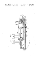
- FIG. 1 A two-stage high-pressure centrifugal pump unit with prime movers in tandem arrangement
- FIG. 2 A two-stage high-pressure centrifugal pump unit with prime movers in tandem arrangement but with pump stages being in reverse arrangement of FIG. 1
- FIG. 3 A two-stage high-pressure centrifugal pump unit, with prime movers being arranged on each side of the pump housing.
- FIG. 4 A two-stage high-pressure centrifugal pump unit, with prime movers being arranged, as per FIG. 3, however with an interposed transmission for the drive of the high-pressure stage.
- a unit is provided where a one-part or multi-part pump housing 3 contains a suction stage 1 and a high-pressure stage 2. Flanged onto the suction side of the pump housing 3, is a low-speed direct-current motor 4, with or without variable speed, which is supplied from the grid with alternating or direct current, via a diode or thyristor acting as rectifier.
- the motor 4 drives the suction stage 1 via the hollow shaft 6. Flanged in tandem arrangement onto the motor 4, is a high-speed direct-current motor 5 with, or without, variable speed, supplied from the grid with alternating or direct current, via a diode or thyristor acting as rectifier, and which drives the high-pressure stage 2 via the solid shaft 7 which runs through the hollow shaft 6.
- FIG. 2 shows an embodiment of the invention where a known high-speed, direct-current motor 5', with, or without, variable speed, supplied from the grid with alternating or direct-current, via a diode or thyristor acting as rectifier, is flanged onto the pressure side of the pump housing 3', driving, via the hollow shaft 6' the high-pressure side 2'.
- a known low-speed direct-current motor 4' which is supplied from the grid with alternating or direct-current, via a diode or thyristor acting as rectifier, driving the suction stage 1' via a solid shaft 7' which runs through the hollow shaft 6'.
- FIG. 3 shows an embodiment of the invention where the pump housing 3" contains a suction stage 1" and a high-speed stage 2". Each stage is driven, independent of each other, via the shaft 9 by a known high-speed or low-speed respectively direct-current motor 4", 5" with or without, variable speed, supplied from the grid with alternating or direct-current, via a diode or thyristor acting as rectifier.
- a two-stage unit has been designed, containing within a one-part or multi-part pump housing 3'" a suction stage 1'" and a high-speed stage 2'".
- the suction stage 1'" is directly driven via the shaft 9', by a known low-speed three-phase asynchronous motor, with, or without, variable speed, which is flanged onto the suction side of the pump housing 3'".
- a high-speed stage 2'" is driven by a three-phase asynchronous motor, also a low-speed unit.
- a transmission 8 is in firm attachment between motor 4'" and the pressure side of pump housing 3'".
- the advantages of the invention lie in the fact that a single-stage or multi-stage centrifugal pump of small dimensions and mass, with a low-speed suction stage and one or several high-speed high-pressure stages, is combined in tandem into a compact unit, the stages being driven, simultaneously but independent of each other, at constant or infinitely variable speed, each by a low-speed or high-speed prime mover respectively.
Landscapes
- Engineering & Computer Science (AREA)
- Mechanical Engineering (AREA)
- General Engineering & Computer Science (AREA)
- Structures Of Non-Positive Displacement Pumps (AREA)
Applications Claiming Priority (2)
| Application Number | Priority Date | Filing Date | Title |
|---|---|---|---|
| DD205616 | 1978-05-29 | ||
| DD78205616A DD136520A1 (de) | 1978-05-29 | 1978-05-29 | Hochdruckkreiselpumpenaggregat |
Publications (1)
| Publication Number | Publication Date |
|---|---|
| US4274803A true US4274803A (en) | 1981-06-23 |
Family
ID=5512804
Family Applications (1)
| Application Number | Title | Priority Date | Filing Date |
|---|---|---|---|
| US06/037,022 Expired - Lifetime US4274803A (en) | 1978-05-29 | 1979-05-08 | High-pressure centrifugal pump unit |
Country Status (7)
| Country | Link |
|---|---|
| US (1) | US4274803A (de) |
| JP (1) | JPS5554689A (de) |
| AT (1) | AT361778B (de) |
| DD (1) | DD136520A1 (de) |
| DE (1) | DE2912958B2 (de) |
| FR (1) | FR2427493A1 (de) |
| GB (1) | GB2024327A (de) |
Cited By (4)
| Publication number | Priority date | Publication date | Assignee | Title |
|---|---|---|---|---|
| US5704768A (en) * | 1993-10-13 | 1998-01-06 | Ebara Corporation | Motor pump family of centrifugal pumps |
| US6164910A (en) * | 1998-09-22 | 2000-12-26 | Itt Manufacturing Enterprises, Inc. | Housing assembly for a fluid-working device such as a rotary pump |
| US6350105B1 (en) * | 1997-04-25 | 2002-02-26 | Ebara Corporation | Frequency and current control for fluid machinery |
| CN103711709A (zh) * | 2012-10-09 | 2014-04-09 | 雷泽永 | 一种可取代高压电机变频调速器的节能泵 |
Families Citing this family (3)
| Publication number | Priority date | Publication date | Assignee | Title |
|---|---|---|---|---|
| DE3811773A1 (de) * | 1988-04-08 | 1989-10-19 | Pierburg Gmbh | Brennstoffversorgungseinrichtung fuer eine brennkraftmaschine |
| DE4005923C2 (de) * | 1990-02-24 | 1994-08-18 | Klein Schanzlin & Becker Ag | Kreiselpumpe mit Laufrädern unterschiedlicher Drehzahl |
| FR2787527B1 (fr) * | 1998-12-22 | 2001-03-09 | Jeumont Ind | Dispositif motorise a circulation centrifuge de fluide, tel qu'une motopompe ou un motocompresseur |
Citations (3)
| Publication number | Priority date | Publication date | Assignee | Title |
|---|---|---|---|---|
| GB157941A (en) * | 1916-10-12 | 1922-04-10 | Emil Faure | Improvements in centrifugal pumps and engines |
| US2862451A (en) * | 1956-07-16 | 1958-12-02 | John H Holstein | Centrifugal pump |
| US3791760A (en) * | 1972-07-31 | 1974-02-12 | Allis Chalmers | Universal in line and end suction pump arrangement |
-
1978
- 1978-05-29 DD DD78205616A patent/DD136520A1/de unknown
-
1979
- 1979-03-31 DE DE2912958A patent/DE2912958B2/de not_active Withdrawn
- 1979-04-04 AT AT248379A patent/AT361778B/de active
- 1979-05-08 US US06/037,022 patent/US4274803A/en not_active Expired - Lifetime
- 1979-05-16 GB GB7917051A patent/GB2024327A/en not_active Withdrawn
- 1979-05-28 FR FR7913443A patent/FR2427493A1/fr not_active Withdrawn
- 1979-05-29 JP JP6735579A patent/JPS5554689A/ja active Pending
Patent Citations (3)
| Publication number | Priority date | Publication date | Assignee | Title |
|---|---|---|---|---|
| GB157941A (en) * | 1916-10-12 | 1922-04-10 | Emil Faure | Improvements in centrifugal pumps and engines |
| US2862451A (en) * | 1956-07-16 | 1958-12-02 | John H Holstein | Centrifugal pump |
| US3791760A (en) * | 1972-07-31 | 1974-02-12 | Allis Chalmers | Universal in line and end suction pump arrangement |
Cited By (5)
| Publication number | Priority date | Publication date | Assignee | Title |
|---|---|---|---|---|
| US5704768A (en) * | 1993-10-13 | 1998-01-06 | Ebara Corporation | Motor pump family of centrifugal pumps |
| US6350105B1 (en) * | 1997-04-25 | 2002-02-26 | Ebara Corporation | Frequency and current control for fluid machinery |
| US6164910A (en) * | 1998-09-22 | 2000-12-26 | Itt Manufacturing Enterprises, Inc. | Housing assembly for a fluid-working device such as a rotary pump |
| CN103711709A (zh) * | 2012-10-09 | 2014-04-09 | 雷泽永 | 一种可取代高压电机变频调速器的节能泵 |
| CN103711709B (zh) * | 2012-10-09 | 2016-07-06 | 雷泽永 | 一种可取代高压电机变频调速器的节能泵 |
Also Published As
| Publication number | Publication date |
|---|---|
| ATA248379A (de) | 1980-08-15 |
| AT361778B (de) | 1981-03-25 |
| DE2912958A1 (de) | 1979-12-06 |
| DD136520A1 (de) | 1979-07-11 |
| JPS5554689A (en) | 1980-04-22 |
| FR2427493A1 (fr) | 1979-12-28 |
| GB2024327A (en) | 1980-01-09 |
| DE2912958B2 (de) | 1981-01-08 |
Similar Documents
| Publication | Publication Date | Title |
|---|---|---|
| US6193473B1 (en) | Direct drive compressor assembly with switched reluctance motor drive | |
| US6616421B2 (en) | Direct drive compressor assembly | |
| EP0169682B1 (de) | Fluidmaschine | |
| US2194054A (en) | Pumping system | |
| EP0837224A2 (de) | Spiralverdichter oder Turbine mit permanent Magnetgenerator/Motor | |
| US20020119040A1 (en) | Crossing spiral compressor/pump | |
| US1610454A (en) | Turbine-driven rotary pump | |
| US4274803A (en) | High-pressure centrifugal pump unit | |
| GB2023731A (en) | Multi-stage centrifugal pump | |
| US3751178A (en) | Pump | |
| US4243892A (en) | Energy-efficient fluid medium pumping system | |
| RU79623U1 (ru) | Насосная установка | |
| US5536148A (en) | Turbo vacuum pump | |
| CN110397607A (zh) | 一种高速直驱式双吸离心蒸汽压缩机 | |
| GB2417523A (en) | Multi-stage motor driven pump | |
| GB2036869A (en) | Submersible Motor Pump | |
| GB2024328A (en) | Multi-stage centrifugal compressor | |
| EP0883749B1 (de) | Kompressor | |
| GB2024943A (en) | Two-stage centrifugal pump | |
| KR100331145B1 (ko) | 유체기계시스템 | |
| US1093145A (en) | Turbine-driven auxiliaries. | |
| CN212803607U (zh) | 运行稳定的浸入式多级离心泵 | |
| US3387769A (en) | Multistage turbomachine | |
| CN1912395B (zh) | 中速高压多级离心式鼓风机 | |
| CN1789727A (zh) | 高压多级离心式鼓风机 |
Legal Events
| Date | Code | Title | Description |
|---|---|---|---|
| AS | Assignment |
Owner name: VEB KOMBINAT PUMPEN UND VERDICHTER DDR 402 HALLE T Free format text: ASSIGNMENT OF ASSIGNORS INTEREST;ASSIGNORS:SPENGLER, HANS;STOOF, KLAUS;REEL/FRAME:003812/0179 Effective date: 19790315 |