US4277192A - End of line locking mechanism for power operated typewriter - Google Patents
End of line locking mechanism for power operated typewriter Download PDFInfo
- Publication number
- US4277192A US4277192A US06/001,587 US158779A US4277192A US 4277192 A US4277192 A US 4277192A US 158779 A US158779 A US 158779A US 4277192 A US4277192 A US 4277192A
- Authority
- US
- United States
- Prior art keywords
- printing
- control lever
- lever
- clutch
- carriage
- Prior art date
- Legal status (The legal status is an assumption and is not a legal conclusion. Google has not performed a legal analysis and makes no representation as to the accuracy of the status listed.)
- Expired - Lifetime
Links
- 230000033001 locomotion Effects 0.000 claims description 17
- 230000000881 depressing effect Effects 0.000 claims 2
- 230000000994 depressogenic effect Effects 0.000 abstract description 31
- 230000008878 coupling Effects 0.000 description 10
- 238000010168 coupling process Methods 0.000 description 10
- 238000005859 coupling reaction Methods 0.000 description 10
- 230000005540 biological transmission Effects 0.000 description 2
- 230000000694 effects Effects 0.000 description 2
- 230000000717 retained effect Effects 0.000 description 2
- 230000002093 peripheral effect Effects 0.000 description 1
Images


Classifications
-
- B—PERFORMING OPERATIONS; TRANSPORTING
- B41—PRINTING; LINING MACHINES; TYPEWRITERS; STAMPS
- B41J—TYPEWRITERS; SELECTIVE PRINTING MECHANISMS, i.e. MECHANISMS PRINTING OTHERWISE THAN FROM A FORME; CORRECTION OF TYPOGRAPHICAL ERRORS
- B41J29/00—Details of, or accessories for, typewriters or selective printing mechanisms not otherwise provided for
- B41J29/54—Locking devices applied to printing mechanisms
- B41J29/58—Locking devices applied to printing mechanisms and automatically actuated
- B41J29/64—Locking devices applied to printing mechanisms and automatically actuated by a function of the printer to lock the keyboard
- B41J29/66—Locking devices actuated when platen reaches the end of a line
Definitions
- This invention relates to an end of line locking mechanism for power operated typewriters which can prevent a printing operation after the right-hand margin position has been reached and becomes operative.
- Typewriters include a right-hand margin which is operative with the movement of the carriage caused when each key or the space bar of the keyboard is depressed. There has been a need for a line lock mechanism capable of positively preventing a printing operation after the right-hand margin position has been reached and becomes operative.
- a line lock mechanism for typewriters is disclosed in Selectric Instruction Manual published in 1964 by IBM Corporation which includes a lock lever adapted to be held between two of a plurality of balls arranged in a row.
- a conventional line lock mechanism is expensive, requires higher assembling accuracy, is unsuitable for use in inexpensive typewriters, and is insufficient to fully prevent the printing operation after the right-hand margin position has been reached and becomes operative during high speed typing operation.
- Another object of the present invention is to provide a line lock mechanism for electric typewriters which can lock a printing clutch in its disengaged state when the right-hand margin position has been reached so as to prevent a printing operation thereafter.
- Still another object of the present invention is to provide a line lock mechanism particularly suitable for use in an inexpensive power operated typewriter which can prevent a printing operation after the right-hand margin position has been reached and becomes operative.
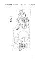
- FIGS. 1 to 5c illustrate a first embodiment of a line lock mechanism constructed in accordance with the present invention.
- FIG. 1 is a sectional view showing the main portion of a typewriter.
- FIG. 2 is a perspective view of the typewriter.
- FIG. 3 is an enlarged sectional view showing a clutch mechanism.
- FIG. 4 is an enlarged sectional view showing a clutch member, clutch control lever, holding lever, and lock member.
- FIGS. 5a to 5c are sectional views used to explain the operation of the components of FIG. 4.
- FIGS. 6 to 7c illustrate a second embodiment of the present invention.
- FIG. 6 is a sectional view showing the main portion of the second embodiment.
- FIGS. 7a to 7c are sectional views used in explaining the operation of the components of FIG. 6.
- FIGS. 8 to 10c illustrate a third embodiment of the present invention.
- FIG. 8 is a perspective view showing the main portion of the third embodiment.
- FIG. 9 is an enlarged sectional view of the main portion of FIG. 8.
- FIGS. 10a to 10c are sectional views used in explaining the operation of the components of FIG. 9.
- FIGS. 11 to 13c illustrate a fourth embodiment of the present invention.
- FIG. 11 is a perspective view showing the main portion of the fourth embodiment.
- FIG. 12 is an enlarged sectional view showing the main portion of FIG. 11.
- FIGS. 13a to 13c are sectional views used to explain the operation of the components of FIG. 12.
- FIGS. 1 to 5c there is shown a first embodiment of a line lock mechanism constructed in accordance with the present invention.
- a carriage 1 is mounted for leftward and rightward movement on a base plate 3 provided in the rear portion of a machine frame 2 and carries a platen 4 thereon.
- a support table 5 is rotatably mounted on a support shaft 6 in front of the carriage 1.
- a printing head 7 is supported for tilting and rotating motion on the support table 5 and has a number of types arranged on its outer surface in rows and columns.
- a number of key levers 8 are rotatably supported on a support shaft 9 transversely extending in the front portion of the machine frame 2, each of which has a key 8a on its upper side and a projection 8b extending downward from its lower side.
- a space bar 10 is provided for downward movement (in the right side of the keys 8a in FIG. 1).
- Resilient operation plates 11 are arranged below each projection 8b of each corresponding key lever 8 and have their front ends secured to the machine frame 2 and the other ends 11a bent downward.
- Interposers 12 are respectively arranged below each corresponding key lever 8, each of which is formed in its rear end portion with an elongated aperture 12a in which a support shaft 13 is loosely inserted to support the interposers 12 such that the interposers 12 can move rotatably and can reciprocate.
- Each of the interposers 12 has on its upper side a shoulder portion 12b facing the bent portion 11a of the corresponding operation plate 11.
- the interposer 12 also has an operating projection 12c, tilt selection stepped portions 12d and 12e, a clutch operating projection 12f, and a rotate selection projection 12g arranged on its lower side in the front-to-back direction.
- Each interposer 12 is urged upward and forward to be held in its original position by means of a leaf spring 14 secured to the machine frame 2 and placed in pressure contact with the rotate selection projection 12g thereof, and can be rotated downward from the original position through each operation plate 11 when a key lever 8 having thereon a key 8a is depressed to push down the corresponding operation plate 11.
- the operating projections 12f of the interposers 12 are in contact with a clutch operating rod 15 which is rotatably mounted at its opposite ends on the machine frame 2 and is spring biased in the counterclockwise direction in FIG. 1 by means of a tension spring 16.
- a clutch operating lever 17 is rotatably mounted on the machine frame 2 and is engaged at its upper end portion with the clutch operating rod 15 such that it can be rotated in the counterclockwise direction in FIG. 1 by the clutch operating rod 15 when an interposer 12 is pushed down, and the clutch operating lever 17 can be returned to the original position, which will be described later when the interposer 12 is released.
- a drive plate 18 is rotatably mounted through the rotary shaft 19 on the machine frame 2 in the position facing the operating projections 12c of the respective interposers 12, which is rotated a predetermined angle by a clutch mechanism to be described later to rearwardly push the operating projection 12c of the interposer 12 downwards when the corresponding key 8a is depressed.
- the rearward movement of the interposer 12 causes the stepped portions 12d and 12e to drive the tilt selection mechanism (not shown) so as to tilt the printing head 7 a predetermined angle thereby placing the desired type row into the position facing the printing position on the platen 4 and also the rotate selection projection 12g to drive the rotate selection mechanism (not shown) through the leaf spring 14 so as to rotate the printing head 7 by a predetermined angle thereby placing the desired type column into the position facing the printing position on the platen 4, whereby the type corresponding to the letter indicated on the desired key 8a can be placed into the position facing the printing position on the platen 4.
- a drive shaft 20 is rotatably mounted on the machine frame 2.
- a drive motor 21 is coupled through a suitable coupling mechanism to the drive shaft 20 to rotate it in the direction indicated by the arrow of FIG. 2.
- a drive gear 22 is rotatably mounted on the drive shaft 20 and has on its one side surface a substantially cylindrical clutch member 23 formed on its outer peripheral surface with two clutch pawls 23a.
- a clutch spring 24 is wound around the drive shaft 20 within the clutch member 23 and fixed at its one end only to the clutch member 23 as best shown in FIG. 3.
- the clutch spring 24 serves to allow rotation of the drive shaft 20 alone when rotation of the clutch member 23 is restricted, and allow the transmission of rotation of the drive shaft 20 to the clutch member 23 and the drive gear 22 when the clutch member 23 can freely rotate.
- the printing clutch mechanism is composed of clutch member 23 and the clutch spring 24.
- a clutch control lever 25 is rotatably mounted in the vicinity of the clutch member 23 on a support shaft 26 secured to the machine frame 2.
- the clutch control lever 25 has on its upper end an engagement portion 25a engageable with and disengageable from one of the clutch pawls 23a of the clutch member 23 and has on its lower end a holding portion 25b.
- a cam follower 27 is mounted on the clutch control lever 25.
- a tension spring 28 is provided to urge the clutch control lever 25 in such a direction that the engagement portion 25a is held out of engagement from the clutch pawls 23a.
- a latch lever 29 is rotatably mounted in the vicinity of the clutch control lever 25 on a support shaft 30 secured on the machine frame 2.
- the latch lever 29 has on its front end a hook portion 29a engageable with and disengageable from the holding portion 25b of the clutch control lever 25 and an arm portion 29b connected with a coupling rod 31 which extends to the clutch operating lever 17.
- a tension spring 32 is provided to bias the latch lever 29 in such a direction that the hook portion 29a can be held in engagement with the holding portion 25b of the clutch control lever 25 thereby normally holding the clutch control lever 25 in a first position where the engagement portion 25a of the clutch control lever 25 is in engagement with the clutch pawl 23a of the clutch member 23 as shown in FIG. 4 so as to release the clutch spring 24.
- a cam shaft 33 extending in parallel with the drive shaft 20 is rotatably mounted on the machine frame 2.
- the cam shaft 33 has thereon a driven gear 34 in engagement with the drive gear 22 so that rotation of the drive shaft 20 can be transmitted through the drive gear 22 and the driven gear 34 to the cam shaft 33 when a desired key lever 8 is depressed to engage the clutch spring 24.
- the driven gear 34 and the drive gear 22 are designed so as to rotate together with ratio of 2 by 1.
- a return cam 35 is secured to the cam shaft 33 adjacent to the driven gear 34. The return cam 35 is moved into engagement with the cam follower 27 with the rotation of the cam shaft 33 to temporarily return the clutch control lever 25 against the force of the tension spring 28 from the second position as shown in FIG.
- a drive cam 36 is secured to one end of the cam shaft 33 and a lever 37 is rotatably mounted on the machine frame 2 in the vicinity of the drive cam 36.
- the lever 37 has on its arm portion a cam follower 38 rotatably mounted thereon and in engagement with the drive cam 36.
- a coupling plate 39 is secured to one end of the rotary shaft 19 extending below the interposers 12.
- a coupling rod 40 connects the coupling plate 39 with the lever 37.
- a tension spring 41 is interposed between the coupling plate 39 and the machine frame 2 to urge the cam follower 38 into pressure contact with the drive cam 36 through the coupling rod 40 and also to normally hold the drive plate 18 in the upright position as shown in FIG. 1.
- a printing mechanism for operating the printing head 7 when a key lever 8 is depressed will be described.
- an operation cam 42 is secured to the cam shaft 33 and an operation lever 43 is rotatably mounted on the machine frame 2 in the vicinity of the operation cam 42.
- the operation lever 43 has on its front end a cam follower 44 rotatably mounted thereon and placed in engagement with the operation cam 42.
- the operation lever 43 also has on its rear end an operation portion 43a placed in engagement with the lower side of the support table 5 on which the printing head 7 is supported.
- a tension spring 45 is interposed between the support table 5 and the machine frame 2 to normally hold the printing head 7 in the original position as shown in FIG. 1.
- the drive plate 18 rotates to push the interposer 12 rearward thereby driving the tilt selection mechanism and the rotate selection mechanism so as to selectively place a type corresponding to the key lever 8 into the position facing the printing position on the platen 4.
- the operation cam 42 operates the operation lever 43 so as to rotate the support table 5 and thus the printing head 7 in the direction indicated by the arrow in FIG. 1, whereby the selected type can print a letter on a paper sheet placed on the platen 4.
- a rotary shaft 46 is rotatably mounted on the base plate 3, which has on its upper end a pinion 48 arranged in engagement which a rack plate 47 mounted on the lower surface of the carriage 1.
- a ratchet wheel 49 is mounted centrally on the rotary shaft 46 and biased to rotate in one direction through the rack plate 47 and the pinion 48 by a suitable biasing means (not shown) urging the carriage 1 in the letter feed direction.
- An escapement mechanism (not shown) of a conventional type having a pair of hook pawls or the like is disposed in the position facing to the ratchet wheel 49.
- the hook pawls alternatively come into engagement with the ratchet wheel 49 to move the carriage 1 half a pitch in the letter feed direction when a key lever 8 is depressed to drive the printing head 7 or when the space bar 10 is depressed and then the carriage 1 further moves half a pitch in the letter feed direction when the printing head 7 returns to the original position or the space bar 10 returns to the original position so that the carriage 1 moves one pitch in the letter feed direction every time a key lever 8 or the space bar 10 is operated.
- a line lock mechanism i.e., the so called right-hand margin lock mechanism for locking the printing clutch mechanism will now be described, which is in its disengaged condition after accomplishment of a printing operation on the last position of a printing line of the paper sheet placed on the platen 4 so as to prevent the next printing operation.
- a margin rack 50 is provided on the carriage 1.
- a right margin stop 51 is movably supported on the margin rack 50, and selectively positioned in a desired position by engaging with a rack portion of the margin rack 50 so as to define a position corresponding to a desired last printing position of the printing line.
- a carriage stopper 52 is supported in the machine frame 2 and engageable with the margin stop 51 such that it can be moved a predetermined distance in the leftward and rightward directions.
- the carriage stopper 52 has its upper side formed with an engagement projection 52a for engagement with the margin stop 51 and its lower side formed with a spring mounting leg 52b, an operation leg 52c, and an engagement pin 52d.
- a weak tension spring 53 is interposed between the spring mounting leg 52b and the machine frame 2 to urge the carriage stopper 52 in the rightward direction in FIG. 2.
- a stop lever 54 is rotatably mounted on the machine frame 2 for engagement with the engagement pin 52d and a strong tension spring 55 is interposed between the stop lever 54 and the machine frame 2 to normally hold the stop lever 54 in engagement with a fixed stopper 56.
- the carriage stopper 52 is held in its original position lying substantially midway in its movement range by the combination of the weak tension spring 53 and the stop lever 54.
- the carriage stopper 52 is adapted to come into engagement with the margin stop 51, which is moved with movement of the carriage 1 in the letter feed direction, when the carriage 1 comes to a position one letter before the last printing position.
- the carriage stopper 52 is moved one pitch leftward in FIG. 2 from the original position to the first shifting position when the carriage 1 moves to the last printing position, and is further moved one pitch leftward from the first shifting position to a second shifting position when the carriage 1 moves further from the last printing position in the letter feed direction.
- a lock member 57 is rotatably mounted on the support shaft 30 in the vicinity of the latch lever 29 and has on its front end a hook portion 57a engageable with and disengageable from the holding portion 25b of the clutch control lever 25 such that the distance L2 between the stepped portion of the hook portion 57a of the lock member 57 and the center of support shaft 30 is shorter than the distance L1 between the stepped portion of the hook portion 29a of the latch lever 29 and the center of the support shaft 30 as shown in FIG. 4.
- a tension spring 58 is provided to urge the lock member 57 toward an operative position where the hook portion 57a of the lock member 57 is engageable with the holding portion 25b of the clutch control lever 25.
- An actuating member 59 is disposed between the carriage stopper 52 and the lock member 57 and is rotatably mounted on the machine frame 2 as shown in FIG. 2.
- the actuating member 59 has a substantially L-shaped lever 60 formed at its one end with a bifurcated portion 60a holding therebetween the operating leg 52c of the carriage stopper 52, and operation plate 61 pivoted at its rear end to the other end of the L-shaped lever 60 and abutting at its front end on the lock member 57.
- the actuating member 59 is normally held in its original position as shown in FIG. 2 by the forces of the tension springs 53 and 55 acting on the carriage stopper 52 to push the lock member 57 against the force of the tension spring 58 so as to retain the lock member 57 in an inoperative position where the hook portion 57a is out of engagement from the holding portion 25b of the clutch control lever 25 as shown in FIG. 4.
- the margin stop 51 comes into engagement with the carriage stopper 52 supported on the carriage 1 positioned at one letter before the last printing position and pushes the carriage stopper 52 from its original position to the first position with movement of the carriage 1 to the last printing position as described above, the actuating member 59 moves from the original position as shown in FIG.
- FIGS. 6 to 7c illustrate a second embodiment of the present invention which is generally similar to the first described embodiment except for the latch lever and lock member arrangement. Accordingly, the same parts are designated by the same reference numerals as used in connection with the first embodiment and will not be described further.
- the latch lever 129 has an additional hook portion 129c other than the hook portion 129a (hereinafter the former is referred to as a second hook portion 129c and the latter as a first hook portion 129a).
- the arm portion 129b of this embodiment functions in the same manner as the arm portion 29b.
- the lock member 67 has on its front end a hook portion 67a engageable with and disengageable from the holding portion 25b of the clutch control lever 25.
- the lock member 67 is normally held in its inoperative position as shown in FIG. 6 where the hook portion 67a is out of engagement from the holding portion 25b of the clutch control lever 25 upon engagement of operation plate 61 of the actuating member 59 with lock member 67.
- the margin stop 51 supported on the carriage 1 comes into engagement with the carriage stopper 52 at one letter before the last printing position, and moves the carriage stopper 52 from the original position to the first position when the carriage 1 moves to the last printing position, whereby the operation plate 61 of the actuating member 59 is retracted.
- the second embodiment is constructed such that the lock member 67 can lock the clutch control lever 25 positioned in the vicinity of the first position so as to hold the clutch spring 24 in the disengaged condition with movement of the carriage stopper 52 caused when the carriage 1 moves over the last printing position.
- the lock member 67 will rotate to the operating position where it can lock the clutch control lever 25 retained in the first position by the first hook portion 29a of the latch lever 29 upon the movement of the carriage 1 over the last printing position. Under this condition, a small clearance is formed between the hook portion 67a of the lock member 67 and the holding portion 25b of the clutch control lever 25 and even if a key lever 8 is thereafter depressed to push the corresponding interposer 12 down thereby rotating the latch lever 29 in such a direction that the latch lever 29 is released from the clutch control lever 25 as shown by the dotted line in FIG.
- the lock member 67 will lock the clutch control lever 25 after the clutch control lever 25 is slightly rotated from the first position toward the second position by the force of the tension spring 28 so as to hold the clutch spring 24 in the disengaged condition thereby positively preventing any printing operation even if the key lever 8 is depressed.
- the key lever 8 is released under this condition and the latch lever 29 placed in the position as shown by the dotted line in FIG. 7 b is returned by the force of the tension spring 32, the second hook portion 29c of the latch lever 29 comes to a position opposite to the holding portion 25b of the clutch control lever 25 with a small clearance as shown in FIG. 7c.
- the latch lever 29 will hold the clutch control lever 25 in the vicinity of the first position so as to retain the clutch spring 24 in the disengaged condition thereby preventing the occurrence of mis-printing-operation.
- FIGS. 8 to 10c illustrate a third embodiment of the present invention which includes a latch lever 29 having two hook portions 129a, 129c similar to that used in the second embodiment, a lock member 57 similar to that used in the first embodiment, and another lock member 67 similar to that used in the second embodiment (hereinafter the former is referred to as a first lock member 57 and the latter as a second lock member 67).
- the first and second lock members 57 and 67 are normally held in the inoperative positions where the hook portions 57a and 67a are out of engagement from the holding portion 25b of the clutch control lever 25 by the operation plate 61 of the actuating member 59 abutting on the lock members 57 and 67.
- the margin stop 51 supported on the carriage 1 comes into engagement with the carriage stopper 52 at one letter before the last printing position of the printing line, and moves the carriage stopper 52 from the original position to the first position when the carriage 1 moves to the last printing position, whereby the operation plate 61 is retracted.
- first lock member 57 rotates to a position where it can be lockable with the clutch control lever 25 positioned in the first position or the hook portion 57a is in abutment on the upper edge of the holding portion 25b of the clutch control lever 25 and also allows the second lock member 67 to rotate to a position just before the position where the second lock member 67 can come into engagement with the holding portion 25b of the clutch control lever 25 as shown in FIG. 10a.
- the carriage stopper 52 is moved from the first position to the second position and thus the operation plate 61 is further retracted from the position as shown in FIG. 10a, whereby the second lock member 67 is rotated to a position as shown in FIG. 10b where the second lock member 67 can be lockable with the clutch control lever 25 positioned in the vicinity of the first position.
- Small clearances are formed between the first hook portion 29a of the latch lever 29 and the holding portion 25b of the clutch control lever 25 and between the hook portion 67a of the second lock member 67 and the holding portion 25b of the clutch control lever 25.
- the first lock member 57 already locks the clutch control lever 25 in the third portion so as to hold the clutch spring 24 in the disengaged condition, thereby positively preventing any printing operation.
- the escapement mechanism moves the carriage 1 from the last printing position in the letter feed direction without any printing operation.
- the carriage stopper 52 is moved from the first position to the second position and the operation plate 61 is further retracted from the position as shown in FIG. 10a.
- the hook portion 57a of the first lock member 57 is held in abutment on the upper edge of the holding portion 25b of the clutch control lever 25 as shown in FIG. 10c, whereas the second lock member 67 is rotated to the operative position where it is lockable with the clutch control lever 25 positioned in the first position with retracting movement of the operation plate 61.
- the latch lever 29 will be positioned in the position where the second hook portion 29c of the latch lever 29 can lock the clutch control lever 25 and even if the carriage 1 returns thereafter so as to rotate the second lock member 67 in such a direction that the second lock member 67 is released from the clutch control lever 25, the clutch control lever 25 will be locked in the vicinity of the first position by the second hook portion 29c, whereby the clutch spring 24 is held in the disengaged condition.
- FIGS. 11 to 13c show a fourth embodiment of the present invention which includes a latch lever 29 similar to that used in the first embodiment, a lock member 57 similar to that used in the first embodiment, and an additional lock member 77 (hereinafter the former is referred to as a first lock member 57 and the latter as a second lock member 77). As shown in FIG.
- the operation plate 61 of the actuating member 59 has at the other end a portion turned upward to form the second lock member 77 which is positioned to a position where it can come into engagement with the holding portion 25b of the clutch control lever 25 positioned in the first position so as to lock the clutch control lever 25 when the carriage 1 moves over the last printing position and the carriage stopper 52 moves from the first position to the second position to thereby retract the operation plate 61.
- first and second lock members 57 and 77 are normally held in the inoperative positions respectively as shown in FIG. 12 where they are out of engagement from the clutch control lever 25 in the same manner as described in connection with the third embodiment.
- the first lock member 57 is rotated to the position where it can come in engagement with the clutch control lever 25 positioned in the first position, as shown in FIG. 13a.
- a key lever 8 is thereafter depressed to effect a printing operation on the last printing position and the clutch control lever 25 is temporarily returned to the third position by the function of the return cam 35, the clutch control lever 25 is locked by the first lock member 57 as shown in FIG. 13b.
- a typewriter comprising a printing mechanism driven every time a key lever is depressed, an escapement mechanism driven in synchronism with the operation of the printing mechanism for intermittently moving the carriage in the letter feed direction, a printing clutch interposed between a drive motor and the printing mechanism, a control lever for engaging the printing clutch when a key lever is depressed to print a letter on the last printing position or when a space bar is depressed to move the carriage from the last printing position in the letter feed direction, and a lock member for locking the control lever so as to hold the printing clutch in its disengaged condition, which can positively prevent any printing operation even if a key lever is depressed after the carriage moves over the last printing position which is defined by the right-hand margin stop.
Landscapes
- Accessory Devices And Overall Control Thereof (AREA)
- Character Spaces And Line Spaces In Printers (AREA)
Applications Claiming Priority (2)
| Application Number | Priority Date | Filing Date | Title |
|---|---|---|---|
| JP1072978A JPS54104916A (en) | 1978-02-01 | 1978-02-01 | Lockkup mechanism for typewriter |
| JP53-10729 | 1978-02-01 |
Publications (1)
| Publication Number | Publication Date |
|---|---|
| US4277192A true US4277192A (en) | 1981-07-07 |
Family
ID=11758376
Family Applications (1)
| Application Number | Title | Priority Date | Filing Date |
|---|---|---|---|
| US06/001,587 Expired - Lifetime US4277192A (en) | 1978-02-01 | 1979-01-08 | End of line locking mechanism for power operated typewriter |
Country Status (2)
| Country | Link |
|---|---|
| US (1) | US4277192A (2) |
| JP (1) | JPS54104916A (2) |
Families Citing this family (1)
| Publication number | Priority date | Publication date | Assignee | Title |
|---|---|---|---|---|
| JPH0658973U (ja) * | 1993-01-26 | 1994-08-16 | 光初 楊 | ゲート・ボール・セット |
Citations (8)
| Publication number | Priority date | Publication date | Assignee | Title |
|---|---|---|---|---|
| US3086635A (en) * | 1961-07-14 | 1963-04-23 | Ibm | Keylever storage mechanism |
| US3195707A (en) * | 1962-07-16 | 1965-07-20 | Royal Mcbee Corp | Keylever signal storing mechanism |
| US3353646A (en) * | 1966-09-14 | 1967-11-21 | Ibm | Typewriter having means to store characters selected during carriage movements |
| US3382963A (en) * | 1966-08-17 | 1968-05-14 | Ibm | Printing apparatus with no-print feature |
| US3404766A (en) * | 1966-09-19 | 1968-10-08 | Ibm | Variable spacebar mechanism for automatically operated proportional escapement printer |
| US3592313A (en) * | 1968-07-15 | 1971-07-13 | Ibm | Encoding keyboard having dual-output shift key |
| US3827542A (en) * | 1971-11-29 | 1974-08-06 | Triumph Werke Nuernberg Ag | Character storage arrangement for a powered typewriter action |
| US3871505A (en) * | 1972-10-13 | 1975-03-18 | Olympia Werke Ag | No-print key control |
-
1978
- 1978-02-01 JP JP1072978A patent/JPS54104916A/ja active Granted
-
1979
- 1979-01-08 US US06/001,587 patent/US4277192A/en not_active Expired - Lifetime
Patent Citations (8)
| Publication number | Priority date | Publication date | Assignee | Title |
|---|---|---|---|---|
| US3086635A (en) * | 1961-07-14 | 1963-04-23 | Ibm | Keylever storage mechanism |
| US3195707A (en) * | 1962-07-16 | 1965-07-20 | Royal Mcbee Corp | Keylever signal storing mechanism |
| US3382963A (en) * | 1966-08-17 | 1968-05-14 | Ibm | Printing apparatus with no-print feature |
| US3353646A (en) * | 1966-09-14 | 1967-11-21 | Ibm | Typewriter having means to store characters selected during carriage movements |
| US3404766A (en) * | 1966-09-19 | 1968-10-08 | Ibm | Variable spacebar mechanism for automatically operated proportional escapement printer |
| US3592313A (en) * | 1968-07-15 | 1971-07-13 | Ibm | Encoding keyboard having dual-output shift key |
| US3827542A (en) * | 1971-11-29 | 1974-08-06 | Triumph Werke Nuernberg Ag | Character storage arrangement for a powered typewriter action |
| US3871505A (en) * | 1972-10-13 | 1975-03-18 | Olympia Werke Ag | No-print key control |
Non-Patent Citations (2)
| Title |
|---|
| IBM Technical Disclosure Bulletin, "Line Lock Mechanism", Palmer, vol. 10, No. 12, May 1968, p. 1911. * |
| IBM Technical Disclosure Bulletin, "Space-to-Print and Print-to-Space Interlock", EMIG, vol. 12, No. 3, Aug. 1969, pp. 471-472. * |
Also Published As
| Publication number | Publication date |
|---|---|
| JPS614672B2 (2) | 1986-02-12 |
| JPS54104916A (en) | 1979-08-17 |
Similar Documents
| Publication | Publication Date | Title |
|---|---|---|
| US2978086A (en) | Key operated machines | |
| US3239049A (en) | Impression control mechanism automatically selecting one of a plurality of cams | |
| US3618736A (en) | Variable force impact printer with backspace mechanism | |
| US3645372A (en) | Automatic type element changing mechanism for single element typewriter | |
| US4277192A (en) | End of line locking mechanism for power operated typewriter | |
| US3721327A (en) | Storing and interlocking typewriter input mechanism | |
| US3346091A (en) | Tabulation apparatus for typewriter | |
| US4172672A (en) | Device for facilitating location of the printing point and/or correction of characters | |
| US3509982A (en) | Automatic letter underscoring mechanism | |
| US4108557A (en) | Error correcting typewriter | |
| US3288262A (en) | Variable spacing mechanism for typewriters and like machines | |
| US3620344A (en) | Selection system for a dual-element typewriter | |
| US3366215A (en) | Single rack backspace | |
| US2896765A (en) | Trip pawl control mechanism | |
| US3647042A (en) | Electrical character select mechanism for typewriter | |
| US3311211A (en) | Keyboard sequence discriminator with different codes for upper and lower case | |
| US3592309A (en) | Cyclically operable typewriter | |
| US4283150A (en) | Typewriter | |
| US3532205A (en) | Printing-carriage back-spacing mechanism for teleprinters | |
| US3730323A (en) | Repeat spacing mechanism for typewriters | |
| US3346089A (en) | Carrier mechanism for proportional escapement typewriter | |
| US3581860A (en) | Method and apparatus for shifting a typing element | |
| US3814228A (en) | Repeat mechanism for a printer | |
| US3934697A (en) | Shift mechanism for typewriter apparatus | |
| US3578131A (en) | Typewriter with extended writing line |
Legal Events
| Date | Code | Title | Description |
|---|---|---|---|
| STCF | Information on status: patent grant |
Free format text: PATENTED CASE |