US4303097A - Digital fluid flow control apparatus - Google Patents
Digital fluid flow control apparatus Download PDFInfo
- Publication number
- US4303097A US4303097A US06/095,292 US9529279A US4303097A US 4303097 A US4303097 A US 4303097A US 9529279 A US9529279 A US 9529279A US 4303097 A US4303097 A US 4303097A
- Authority
- US
- United States
- Prior art keywords
- manifold
- valve body
- face
- cylindrical
- inlet
- Prior art date
- Legal status (The legal status is an assumption and is not a legal conclusion. Google has not performed a legal analysis and makes no representation as to the accuracy of the status listed.)
- Expired - Lifetime
Links
- 239000012530 fluid Substances 0.000 title claims abstract description 40
- 238000007789 sealing Methods 0.000 claims description 11
- 238000004891 communication Methods 0.000 claims description 5
- 238000004140 cleaning Methods 0.000 description 6
- 230000000717 retained effect Effects 0.000 description 6
- 238000011144 upstream manufacturing Methods 0.000 description 6
- 238000007689 inspection Methods 0.000 description 4
- 238000003466 welding Methods 0.000 description 3
- 238000005266 casting Methods 0.000 description 2
- 238000004519 manufacturing process Methods 0.000 description 2
- 230000001681 protective effect Effects 0.000 description 2
- 238000003754 machining Methods 0.000 description 1
- 238000004886 process control Methods 0.000 description 1
Images


Classifications
-
- F—MECHANICAL ENGINEERING; LIGHTING; HEATING; WEAPONS; BLASTING
- F16—ENGINEERING ELEMENTS AND UNITS; GENERAL MEASURES FOR PRODUCING AND MAINTAINING EFFECTIVE FUNCTIONING OF MACHINES OR INSTALLATIONS; THERMAL INSULATION IN GENERAL
- F16K—VALVES; TAPS; COCKS; ACTUATING-FLOATS; DEVICES FOR VENTING OR AERATING
- F16K27/00—Construction of housing; Use of materials therefor
- F16K27/003—Housing formed from a plurality of the same valve elements
-
- Y—GENERAL TAGGING OF NEW TECHNOLOGICAL DEVELOPMENTS; GENERAL TAGGING OF CROSS-SECTIONAL TECHNOLOGIES SPANNING OVER SEVERAL SECTIONS OF THE IPC; TECHNICAL SUBJECTS COVERED BY FORMER USPC CROSS-REFERENCE ART COLLECTIONS [XRACs] AND DIGESTS
- Y10—TECHNICAL SUBJECTS COVERED BY FORMER USPC
- Y10T—TECHNICAL SUBJECTS COVERED BY FORMER US CLASSIFICATION
- Y10T137/00—Fluid handling
- Y10T137/8593—Systems
- Y10T137/87265—Dividing into parallel flow paths with recombining
- Y10T137/87298—Having digital flow controller
- Y10T137/87306—Having plural branches under common control for separate valve actuators
- Y10T137/87314—Electromagnetic or electric control [e.g., digital control, bistable electro control, etc.]
Definitions
- This invention relates to the field of process control and, more particularly, to digital fluid flow control apparatus.
- a plurality of individually actuatable bistable, i.e., ON/OFF, valve elements are connected in parallel between an upstream manifold and a downstream manifold.
- the valve elements have orifices that are weighted in area, usually according to a geometric progression. By selectively opening and closing different combinations of valve elements, the fluid flow rate can be controlled over a wide range from zero to a maximum value.
- Typical digital fluid flow control apparatus is disclosed in U.S. Pat. No. 3,746,041, which is assigned to the assignee of the present application.
- valve body be capable of fabrication without necessity for welding or casting. Greater reliability can be achieved if the parts of such housing have face seals rather than piston seals.
- the invention provides digital fluid control apparatus in which the parts are easily accessible for off-line inspection, cleaning, and repair without removal of the apparatus from the fluid line.
- the apparatus can be scaled to fluid lines having a wide range of diameters.
- the parts of the valve body have face seals and need not be fabricated by welding or casting, although they can be cast if desired.
- One feature of the invention is a two-part valve body for digital fluid flow control apparatus.
- the two parts of the valve body have flat abutting faces.
- a cavity is formed in one part and is surrounded by at least a portion of the flat face of that part to form with the other flat face a first manifold.
- a second manifold is formed in the other part.
- the parts of the valve body are releasably secured with the flat faces in abutment.
- the parts of the valve body are sealed, preferably by a face seal between the flat faces, and the parts are secured by a clamp that urges the flat faces together against the face seal.
- the part in which the second manifold is formed comprises subparts that are also releasably secured.
- a valve body for digital fluid flow control apparatus has first and second laterally displaced cylindrical manifolds with aligned axes, an inlet port transverse to the manifold axes, and an outlet port transverse to the manifold axes.
- the first manifold lies between the second manifold and both ports.
- a generally cylindrical valve body has a cylindrical axis, an inlet to the valve body has an axis extending radially from the cylindrical axis, and an outlet from the valve body has an axis extending radially from the cylindrical axis in the same plane as the inlet axis.
- a cylindrical manifold is coaxially disposed in the valve body in laterally displaced relationship with the inlet and outlet.
- An annular manifold is coaxially disposed in the valve body in laterally spaced relationship with the inlet and outlet; the annular manifold lies between the cylindrical manifold and the inlet and outlet and surrounds a portion of the valve body.
- a passage extends through the valve body from the inlet to one of the manifolds.
- Another passage extends through the valve body from the outlet to the other manifold.
- the passage to the cylindrical manifold passes through the portion of the valve body surrounded by the annular manifold.
- a plurality of digital bistable valve elements connect the cylindrical manifold and the annular manifold.
- the inlet axis and outlet axis are aligned with each other. Fluid flowing through the described valve body traverses more than a 360° path.
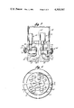
- FIG. 1 is a side-sectional view of apparatus incorporating the principles of the invention in a valve body fabricated from machined parts and;
- FIG. 1A is an enlargement of a designated portion of FIG. 1;
- FIG. 2 is a top plan view of the apparatus of FIG. 1 with the cover removed;
- FIG. 3 is a side-sectional view of apparatus incorporating the principles of the invention in a valve body fabricated from cast parts;
- FIG. 4 is a top plan view of the apparatus of FIG. 3 with the cover removed.
- a generally cylindrical valve body 10 having a cylindrical axis 18 comprises separate generally cylindrical parts 11, 12, and 13 which are clamped together by a plurality of screw fasteners 14.
- Parts 11, 12, and 13 are formed by machining cylindrical billets.
- Parts 13 and 12 have respective first and second flat abutting faces and parts 12 and 11 have respective third and fourth flat abutting faces.
- the third flat face surrounds recess 20.
- Part 11 has a plurality of screw receiving bores 15, e.g., twelve in number, arranged in a ring around axis 18 in parallel relationship thereto and a plurality of larger valve element receiving bores 16, e.g., thirteen in number, arranged in a ring around bores 15 in parallel relationship to axis 18.
- Part 12 has a coaxial cylindrical recess 20 with a diameter almost as large as part 12 formed at one end face adjacent to part 11 and a short coaxial bore 21 connecting recess 20 to the other end face of part 12.
- Part 12 also has a plurality of screw receiving bores 22 equal in number to and aligned with bores 15 and a plurality of bores 23 equal in number to and aligned with bores 16. Bores 22 and 23 each extend through part 12 from the floor of recess 20 to the opposite end face thereof.
- Part 13 has adjacent to part 12 an annular coaxial cavity or recess 24 surrounding a portion 31 of part 13, a cylindrical coaxial cavity or recess 25 surrounded by recess 24, and a plurality of threaded bores 26 equal in number to and aligned with bores 22 and 15.
- One portion of the first flat face surrounds recess 25 and another portion thereof surrounds recess 24.
- a threaded bore 27 having an axis 28 extending radially from axis 18 is formed in part 13 from the outer cylindrical surface thereof to recess 25.
- a threaded bore 29 having an axis 30 extending radially from axis 18 in alignment with axis 28 is formed in part 13 from its outer cylindrical surface to a depth short of recess 25.
- a bore 32 parallel to axis 18 extends between recess 24 and bore 29.
- Screw fasteners 14 extend through bores 15 and 22 and are threaded into bores 26 to releasably secure parts 11, 12, and 13.
- a face seal 35 is disposed between the head of each screw fastener 14, preferably recessed as shown, and the adjacent surface of part 11.
- a face seal 36 is retained in an annular groove formed in the third flat end face, i.e., the end face of part 12 adjacent to part 11. Seal 36 is disposed around the third flat face to prevent fluid leakage from recess 20 to the exterior of valve body 10 between the third and fourth flat faces.
- Face seals 37 and 38 are retained in annular grooves formed in the first flat end face, i.e., the end face of part 13 adjacent to part 12 on the inside and outside, respectively, of recess 24.
- face seal 38 is disposed around the portion of the first face surrounding recess 24, to prevent fluid leakage from recess 24 to the exterior of valve body 10 between the first and second faces
- face seal 37 is disposed around the portion of the first flat face surrounding recess 25 to prevent fluid leakage between recesses 24 and 25 through the interface formed by the first and second flat faces.
- Face seals 35 through 38 serve to seal the interior of valve body 10 effectively without necessity for piston seals, which are inherently less reliable than face seals.
- a plurality of individually actuatable bistable digital valve elements 40 are disposed in bores 16.
- Each valve element 40 comprises an electromagnetic actuator 41, a plunger 42, and a cylindrical orifice block 43, which may be attached to actuator 41.
- Valve element 40 is retained in bore 16 by a snap ring 44.
- Snap ring 44 bears against a washer 45, which in turn bears against the end of actuator 41 to urge it toward a shoulder 46 formed in bore 16.
- An O-ring 56 is retained in an annular groove around actuator 41 to seal the interface between bore 16 and actuator 41. Instead of an O-ring, a face seal could engage shoulder 46.
- Actuator 41 and plunger 42 could be constructed in the manner described in connection with FIG. 1 of the referenced co-pending application.
- Orifice block 43 lies in a shallow counter bore formed in bore 23 adjacent to recess 20.
- a face seal 47 is retained in an annular recess formed in the surface of orifice block 43 adjacent to part 12.
- Orifice block 43 has a cylindrical recess 48 facing toward actuator 41 and a central valve seat 49 extending from the floor of recess 48 toward actuator 41 in alignment with plunger 42.
- the end of plunger 42 adjacent to valve seat 49 has an elastomeric sealing insert 52.
- An orifice 50 is formed by a bore and counter bore extending through orifice block 43 from valve seat 49 to bore 23.
- Orifice 50 is the flow controlling orifice of the valve element, which determines the weighting assigned to such valve element.
- a converging-diverging nozzle could be provided as shown in FIG. 1 of the referenced co-pending application.
- the cylindrical side walls of orifice block 43 have slots 51, which permit fluid communication between recess 20 and recess 48.
- a binary electrical signal drives actuator 41. When the binary signal is one value, plunger 42 is driven against valve seat 49 as shown in FIG. 1 to seal orifice 50; when the binary signal is the other value, plunger 42 is retracted into actuator 41 to permit fluid flow through orifice 50.
- bistable valve element refers to a valve element having a plug or plunger that assumes one of two stable positions, namely, open or closed, depending upon the pressure balancing of the plug element and/or the bistable nature of the actuator and/or electrical driving signal.
- a protective cover 54 is attached to part 11 by fasteners 55.
- Bore 27 serves as an inlet to valve body 10; recess 20 and the adjacent end face of part 11, i.e., the fourth flat end face, define a cylindrical upstream manifold, bore 21 and recess 25 define an upstream connecting passage from the inlet to the cylindrical manifold; bore 29 serves as an outlet from valve body 10; recess 24 and the adjacent end face of part 12, i.e., the second flat end face, define an annular downstream manifold and bore 32 defines a downstream connecting passage from the outlet to the annular manifold.
- the downstream manifold is disposed in valve body 10 in laterally spaced relationship with the inlet and outlet and lies between the upstream manifold and the inlet and outlet.
- Fluid flowing into the inlet makes a 90° change of direction at the upstream connecting passage and another 90° change of direction at the cylindrical manifold.
- Such fluid flows from the cylindrical manifold to the annular manifold through the open valve elements, the fluid flow rate depending upon the weighting assigned to the open valve elements.
- Fluid flowing through the open valve elements from the cylindrical manifold makes a 90° change in direction and another 90° change in direction as it flows into the annular manifold.
- the fluid flows around the annular manifold to the outlet connecting passage where it makes another 90° change in direction as it flows through such passage and finally yet another 90° change in direction as it flows into the outlet.
- the fluid bends more than 360° as it traverses through valve body 10.
- This unique fluid travel configuration permits valve body 10 to be fabricated without welding from machined parts, i.e., parts 11, 12, and 13, which are sealed only by face seals, i.e., seals 35 through 38.
- valve body 10 In order to gain access to the interior of valve body 10 for inspection, cleaning, and repair, it is only necessary to remove fasteners 55 and bolts 14 and break apart parts 11, 12, and 13; it is not necessary to remove valve elements 40 from part 11 unless a specific one of such valve elements requires cleaning or repair.
- valve body 60 comprises cast parts 61 and 62 that have abutting mounting flanges 63 and 64, respectively. Flanges 63 and 64 are held together by bolts 65. When assembled as shown, valve body 60 has the same internal configuration as valve body 10 of FIGS. 1 and 2.
- a cylindrical axis 67 a threaded inlet 68 with an axis 69 extending radially from cylindrical axis 67; and outlet 70 with an axis 71 extending radially from cylindrical axis 67 in alignment with axis 69; a cylindrical manifold 72 coaxially disposed in valve body 60 in laterally displaced relationship with inlet 68 and outlet 70, and an annular manifold 73 coaxially disposed in valve body 60 in laterally spaced relationship with inlet 68 and outlet 70.
- Annular manifold 73 lies between cylindrical manifold 72 and inlet 68 and outlet 70 and surrounds a portion 74 of part 62.
- Face seals 78 and 79 are retained in annular grooves formed in the end face of part 62 adjacent to part 61 on the inside and outside, respectively, of annular manifold 73 to seal the interface between parts 61 and 62.
- a passage 84 extends through valve body 60 including portion 74, from inlet 68 to cylindrical manifold 72.
- a passage 85 extends through valve body 60 from outlet 70 to annular manifold 74. Since valve body 60 is cast, passages 84 and 85 are elbow shaped to provide the smoothest possible flow channel.
- Part 61 has a plurality of axially aligned pairs of bores 86 and 87, e.g., eight in number, arranged in a ring around axis 67, and a plurality of axially aligned pairs of bores 88 and 89, e.g., four in number, arranged in a ring around axis 67 inside of bores 86 and 87.
- a plurality of small valve elements 90 are mounted in the respective bores 86 and 87 and a plurality of large valve elements 91 are mounted in the respective bores 88 and 89.
- Valve elements 90 and 91 could, for example, take the form shown in FIG. 3 of the referenced co-pending application.
- a protective cover 92 fits over valve elements 90 and 91 at the end of part 61 opposite part 62.
- valve elements 90 and 91 do not need to be removed from part 61 unless a particular one of these valve elements needs to be cleaned or repaired.
Landscapes
- Engineering & Computer Science (AREA)
- General Engineering & Computer Science (AREA)
- Mechanical Engineering (AREA)
- Valve Housings (AREA)
- Flow Control (AREA)
- Lift Valve (AREA)
Priority Applications (7)
| Application Number | Priority Date | Filing Date | Title |
|---|---|---|---|
| US06/095,292 US4303097A (en) | 1979-11-19 | 1979-11-19 | Digital fluid flow control apparatus |
| CA000364066A CA1158132A (en) | 1979-11-19 | 1980-11-05 | Digital fluid flow control apparatus |
| DE8080107014T DE3071212D1 (en) | 1979-11-19 | 1980-11-13 | Digital fluid flow control apparatus |
| EP19800107014 EP0029225B1 (de) | 1979-11-19 | 1980-11-13 | Digitaler Fluidstrom-Steuerungsapparat |
| AT80107014T ATE16307T1 (de) | 1979-11-19 | 1980-11-13 | Digitaler fluidstrom-steuerungsapparat. |
| JP16206880A JPS5699514A (en) | 1979-11-19 | 1980-11-19 | Digital fluiddflow controller |
| CA000436542A CA1174940A (en) | 1979-11-19 | 1983-09-12 | Digital fluid flow control apparatus |
Applications Claiming Priority (1)
| Application Number | Priority Date | Filing Date | Title |
|---|---|---|---|
| US06/095,292 US4303097A (en) | 1979-11-19 | 1979-11-19 | Digital fluid flow control apparatus |
Publications (1)
| Publication Number | Publication Date |
|---|---|
| US4303097A true US4303097A (en) | 1981-12-01 |
Family
ID=22251203
Family Applications (1)
| Application Number | Title | Priority Date | Filing Date |
|---|---|---|---|
| US06/095,292 Expired - Lifetime US4303097A (en) | 1979-11-19 | 1979-11-19 | Digital fluid flow control apparatus |
Country Status (6)
| Country | Link |
|---|---|
| US (1) | US4303097A (de) |
| EP (1) | EP0029225B1 (de) |
| JP (1) | JPS5699514A (de) |
| AT (1) | ATE16307T1 (de) |
| CA (1) | CA1158132A (de) |
| DE (1) | DE3071212D1 (de) |
Cited By (11)
| Publication number | Priority date | Publication date | Assignee | Title |
|---|---|---|---|---|
| US4628961A (en) * | 1985-09-19 | 1986-12-16 | Lew Hyok S | Multiple orifice stepper control valve |
| US4768544A (en) * | 1987-05-26 | 1988-09-06 | Beam Engineering, Inc. | Digital valve flow control system |
| US5143120A (en) * | 1990-03-15 | 1992-09-01 | Firma Carl Freudenberg | Electromagnetic valve assembly |
| WO1998047748A1 (de) * | 1997-04-18 | 1998-10-29 | Continental Teves Ag & Co. Ohg | Motorgetriebenes aggregat |
| US5881767A (en) * | 1997-06-04 | 1999-03-16 | Dragerwerk Ag | Modular piezo valve arrangement |
| RU2152068C1 (ru) * | 1998-12-22 | 2000-06-27 | Галицкий Юрий Васильевич | Многопоточный клапан-дроссель |
| RU2185652C2 (ru) * | 2000-01-26 | 2002-07-20 | Открытое акционерное общество "НПО Энергомаш им. академика В.П. Глушко" | Регулятор расхода жидкости |
| RU2185651C2 (ru) * | 2000-01-26 | 2002-07-20 | Открытое акционерное общество "НПО Энергомаш им. академика В.П. Глушко" | Цифровой гидравлический дроссель |
| RU2241249C2 (ru) * | 2002-10-31 | 2004-11-27 | Грачев Вениамин Васильевич | Многопоточный дискретный клапан-дроссель |
| US20110214765A1 (en) * | 2008-11-05 | 2011-09-08 | Norgren Gmbh | Modular valve assembly |
| US20220026007A1 (en) * | 2019-02-06 | 2022-01-27 | John Thompson | Pipe Cap Assembly |
Families Citing this family (7)
| Publication number | Priority date | Publication date | Assignee | Title |
|---|---|---|---|---|
| DE3230162C2 (de) * | 1982-08-13 | 1985-03-14 | Messerschmitt-Boelkow-Blohm Gmbh, 8000 Muenchen | Elektromagnetisches Zweistoffventil |
| FR2548329B1 (fr) * | 1983-06-30 | 1986-06-20 | Bosteels Michel | Dispositif de commande de debits calibres de fluide |
| JPS6076302U (ja) * | 1983-11-01 | 1985-05-28 | 日本電信電話株式会社 | 光ケ−ブル接続部の余長処理ケ−ス |
| GB8712951D0 (en) * | 1987-06-03 | 1987-07-08 | Rolls Royce Plc | Valve |
| DE3810788A1 (de) * | 1988-03-30 | 1989-10-12 | Teves Gmbh Alfred | Ventilblockaggregat |
| JPWO2002061516A1 (ja) * | 2001-01-31 | 2004-06-03 | 株式会社荏原製作所 | バルブユニット及び流量制御システム |
| FR3072440B1 (fr) * | 2017-10-13 | 2019-11-29 | Parker Hannifin Emea S.A.R.L. | Vanne configurable pour la distribution d’un fluide et procede de parametrage de cette vanne |
Citations (9)
| Publication number | Priority date | Publication date | Assignee | Title |
|---|---|---|---|---|
| US3331393A (en) * | 1963-09-13 | 1967-07-18 | Lignes Telegraph Telephon | Digital valve |
| US3351089A (en) * | 1964-06-30 | 1967-11-07 | Garrahan Richard | Control valve for diving apparatus |
| US3375845A (en) * | 1964-04-21 | 1968-04-02 | Houdaille Industries Inc | Fluid flow device |
| US3502105A (en) * | 1966-07-27 | 1970-03-24 | Lignes Telegraph Telephon | Electromagnetic valves and application thereof to digital valves |
| US3726296A (en) * | 1971-08-09 | 1973-04-10 | Process Systems | Fluidic control system and method for calibrating same |
| US3937248A (en) * | 1968-02-06 | 1976-02-10 | Process Systems, Inc. | Fluid flow control system employing a plurality of digital valve elements |
| US4019533A (en) * | 1975-07-17 | 1977-04-26 | Digital Dynamics, Inc. | Digital valve assembly |
| US4199006A (en) * | 1978-02-28 | 1980-04-22 | The United States Of America As Represented By The Secretary Of The Navy | Pneumatic valve |
| US4248263A (en) * | 1971-08-09 | 1981-02-03 | Powell Industries, Inc. | Digital fluid flow control apparatus |
Family Cites Families (4)
| Publication number | Priority date | Publication date | Assignee | Title |
|---|---|---|---|---|
| US2229903A (en) * | 1939-02-04 | 1941-01-28 | Arthur L Parker | Metering valve |
| US2807280A (en) * | 1953-07-20 | 1957-09-24 | Arthur E Kittredge | Program control valve |
| US3746041A (en) * | 1971-02-02 | 1973-07-17 | Process Systems | Fluid flow control system |
| CA1018861A (en) * | 1974-01-10 | 1977-10-11 | Harry Friedland | Digital fluid flow control system |
-
1979
- 1979-11-19 US US06/095,292 patent/US4303097A/en not_active Expired - Lifetime
-
1980
- 1980-11-05 CA CA000364066A patent/CA1158132A/en not_active Expired
- 1980-11-13 EP EP19800107014 patent/EP0029225B1/de not_active Expired
- 1980-11-13 AT AT80107014T patent/ATE16307T1/de not_active IP Right Cessation
- 1980-11-13 DE DE8080107014T patent/DE3071212D1/de not_active Expired
- 1980-11-19 JP JP16206880A patent/JPS5699514A/ja active Pending
Patent Citations (9)
| Publication number | Priority date | Publication date | Assignee | Title |
|---|---|---|---|---|
| US3331393A (en) * | 1963-09-13 | 1967-07-18 | Lignes Telegraph Telephon | Digital valve |
| US3375845A (en) * | 1964-04-21 | 1968-04-02 | Houdaille Industries Inc | Fluid flow device |
| US3351089A (en) * | 1964-06-30 | 1967-11-07 | Garrahan Richard | Control valve for diving apparatus |
| US3502105A (en) * | 1966-07-27 | 1970-03-24 | Lignes Telegraph Telephon | Electromagnetic valves and application thereof to digital valves |
| US3937248A (en) * | 1968-02-06 | 1976-02-10 | Process Systems, Inc. | Fluid flow control system employing a plurality of digital valve elements |
| US3726296A (en) * | 1971-08-09 | 1973-04-10 | Process Systems | Fluidic control system and method for calibrating same |
| US4248263A (en) * | 1971-08-09 | 1981-02-03 | Powell Industries, Inc. | Digital fluid flow control apparatus |
| US4019533A (en) * | 1975-07-17 | 1977-04-26 | Digital Dynamics, Inc. | Digital valve assembly |
| US4199006A (en) * | 1978-02-28 | 1980-04-22 | The United States Of America As Represented By The Secretary Of The Navy | Pneumatic valve |
Cited By (13)
| Publication number | Priority date | Publication date | Assignee | Title |
|---|---|---|---|---|
| US4628961A (en) * | 1985-09-19 | 1986-12-16 | Lew Hyok S | Multiple orifice stepper control valve |
| US4768544A (en) * | 1987-05-26 | 1988-09-06 | Beam Engineering, Inc. | Digital valve flow control system |
| US5143120A (en) * | 1990-03-15 | 1992-09-01 | Firma Carl Freudenberg | Electromagnetic valve assembly |
| US6260582B1 (en) | 1997-04-18 | 2001-07-17 | Continental Teves Ag & Co., Ohg | Motor-driven unit |
| WO1998047748A1 (de) * | 1997-04-18 | 1998-10-29 | Continental Teves Ag & Co. Ohg | Motorgetriebenes aggregat |
| US5881767A (en) * | 1997-06-04 | 1999-03-16 | Dragerwerk Ag | Modular piezo valve arrangement |
| RU2152068C1 (ru) * | 1998-12-22 | 2000-06-27 | Галицкий Юрий Васильевич | Многопоточный клапан-дроссель |
| RU2185652C2 (ru) * | 2000-01-26 | 2002-07-20 | Открытое акционерное общество "НПО Энергомаш им. академика В.П. Глушко" | Регулятор расхода жидкости |
| RU2185651C2 (ru) * | 2000-01-26 | 2002-07-20 | Открытое акционерное общество "НПО Энергомаш им. академика В.П. Глушко" | Цифровой гидравлический дроссель |
| RU2241249C2 (ru) * | 2002-10-31 | 2004-11-27 | Грачев Вениамин Васильевич | Многопоточный дискретный клапан-дроссель |
| US20110214765A1 (en) * | 2008-11-05 | 2011-09-08 | Norgren Gmbh | Modular valve assembly |
| US9194508B2 (en) * | 2008-11-05 | 2015-11-24 | Norgren Gmbh | Modular valve assembly |
| US20220026007A1 (en) * | 2019-02-06 | 2022-01-27 | John Thompson | Pipe Cap Assembly |
Also Published As
| Publication number | Publication date |
|---|---|
| CA1158132A (en) | 1983-12-06 |
| DE3071212D1 (en) | 1985-12-05 |
| JPS5699514A (en) | 1981-08-10 |
| EP0029225A1 (de) | 1981-05-27 |
| EP0029225B1 (de) | 1985-10-30 |
| ATE16307T1 (de) | 1985-11-15 |
Similar Documents
| Publication | Publication Date | Title |
|---|---|---|
| CA1158132A (en) | Digital fluid flow control apparatus | |
| US4830331A (en) | High pressure fluid valve | |
| US5172728A (en) | Three-way-valve | |
| CA2105120C (en) | High differential pressure control valve | |
| CA1292463C (en) | Compact multi-service ball valve | |
| US3550621A (en) | Fluid distributing manifold for directional control valve | |
| US3942553A (en) | Digital fluid flow control system with trim adjustment | |
| US4244396A (en) | Digital fluid flow control system | |
| US4476891A (en) | Multi-component valve | |
| EP0134185B1 (de) | Wegeventil in Modulbauweise | |
| US3937248A (en) | Fluid flow control system employing a plurality of digital valve elements | |
| US4825906A (en) | Angle pattern control valve | |
| US7021332B2 (en) | Hydraulic valve section with reduced bore distortion | |
| WO1997019282B1 (en) | Distribution valve for high pressure coolant used in a metalworking machine application | |
| US5911243A (en) | Multiport conversion system for butterfly valve | |
| US5111840A (en) | Modular valve | |
| US4148340A (en) | Digital fluid flow control system | |
| US4623002A (en) | Polymer control valve | |
| CA1174940A (en) | Digital fluid flow control apparatus | |
| US4256137A (en) | Check valve | |
| US5324008A (en) | Ball valve with offset through-duct | |
| EP3891424B1 (de) | Regelventile | |
| US2998223A (en) | Valve assembly | |
| EP0356185A2 (de) | Fluidsteuerventil | |
| GB2138110A (en) | Improvement in and relating to control valves |
Legal Events
| Date | Code | Title | Description |
|---|---|---|---|
| STCF | Information on status: patent grant |
Free format text: PATENTED CASE |