US4304609A - Drill cuttings treatment apparatus and method - Google Patents
Drill cuttings treatment apparatus and method Download PDFInfo
- Publication number
- US4304609A US4304609A US06/125,531 US12553180A US4304609A US 4304609 A US4304609 A US 4304609A US 12553180 A US12553180 A US 12553180A US 4304609 A US4304609 A US 4304609A
- Authority
- US
- United States
- Prior art keywords
- vessel
- drill cuttings
- retort
- hydrocarbons
- auger
- Prior art date
- Legal status (The legal status is an assumption and is not a legal conclusion. Google has not performed a legal analysis and makes no representation as to the accuracy of the status listed.)
- Expired - Lifetime
Links
- 238000005520 cutting process Methods 0.000 title claims abstract description 41
- 238000000034 method Methods 0.000 title claims abstract description 16
- 238000010438 heat treatment Methods 0.000 claims abstract description 57
- 229930195733 hydrocarbon Natural products 0.000 claims abstract description 37
- 150000002430 hydrocarbons Chemical class 0.000 claims abstract description 37
- 239000007787 solid Substances 0.000 claims abstract description 33
- 230000006698 induction Effects 0.000 claims abstract description 31
- 238000011144 upstream manufacturing Methods 0.000 claims abstract description 14
- 239000000463 material Substances 0.000 claims description 22
- 238000007599 discharging Methods 0.000 claims description 8
- 230000005484 gravity Effects 0.000 claims description 6
- 239000011343 solid material Substances 0.000 claims description 5
- 239000004215 Carbon black (E152) Substances 0.000 abstract description 11
- 230000014759 maintenance of location Effects 0.000 abstract description 7
- 238000004880 explosion Methods 0.000 abstract description 3
- 238000004891 communication Methods 0.000 abstract description 2
- 238000003912 environmental pollution Methods 0.000 abstract description 2
- 238000005553 drilling Methods 0.000 description 12
- 239000012530 fluid Substances 0.000 description 5
- 239000007789 gas Substances 0.000 description 5
- 239000002904 solvent Substances 0.000 description 4
- 238000000197 pyrolysis Methods 0.000 description 3
- CURLTUGMZLYLDI-UHFFFAOYSA-N Carbon dioxide Chemical compound O=C=O CURLTUGMZLYLDI-UHFFFAOYSA-N 0.000 description 2
- 230000015572 biosynthetic process Effects 0.000 description 2
- 230000000694 effects Effects 0.000 description 2
- 239000013072 incoming material Substances 0.000 description 2
- 239000011261 inert gas Substances 0.000 description 2
- 238000011084 recovery Methods 0.000 description 2
- 238000007790 scraping Methods 0.000 description 2
- XLYOFNOQVPJJNP-UHFFFAOYSA-N water Substances O XLYOFNOQVPJJNP-UHFFFAOYSA-N 0.000 description 2
- 230000001464 adherent effect Effects 0.000 description 1
- 229910002092 carbon dioxide Inorganic materials 0.000 description 1
- 239000001569 carbon dioxide Substances 0.000 description 1
- 239000004568 cement Substances 0.000 description 1
- 230000005611 electricity Effects 0.000 description 1
- 238000001704 evaporation Methods 0.000 description 1
- 230000008020 evaporation Effects 0.000 description 1
- 239000003337 fertilizer Substances 0.000 description 1
- 238000009413 insulation Methods 0.000 description 1
- 239000012774 insulation material Substances 0.000 description 1
- QSHDDOUJBYECFT-UHFFFAOYSA-N mercury Chemical compound [Hg] QSHDDOUJBYECFT-UHFFFAOYSA-N 0.000 description 1
- 229910052753 mercury Inorganic materials 0.000 description 1
- 239000004058 oil shale Substances 0.000 description 1
- 239000011236 particulate material Substances 0.000 description 1
- 230000000737 periodic effect Effects 0.000 description 1
- 230000005855 radiation Effects 0.000 description 1
- 239000013557 residual solvent Substances 0.000 description 1
- 230000000717 retained effect Effects 0.000 description 1
- 239000000779 smoke Substances 0.000 description 1
- 238000000638 solvent extraction Methods 0.000 description 1
- -1 stockfeed Substances 0.000 description 1
Images


Classifications
-
- E—FIXED CONSTRUCTIONS
- E21—EARTH OR ROCK DRILLING; MINING
- E21B—EARTH OR ROCK DRILLING; OBTAINING OIL, GAS, WATER, SOLUBLE OR MELTABLE MATERIALS OR A SLURRY OF MINERALS FROM WELLS
- E21B21/00—Methods or apparatus for flushing boreholes, e.g. by use of exhaust air from motor
- E21B21/06—Arrangements for treating drilling fluids outside the borehole
- E21B21/063—Arrangements for treating drilling fluids outside the borehole by separating components
- E21B21/065—Separating solids from drilling fluids
-
- C—CHEMISTRY; METALLURGY
- C10—PETROLEUM, GAS OR COKE INDUSTRIES; TECHNICAL GASES CONTAINING CARBON MONOXIDE; FUELS; LUBRICANTS; PEAT
- C10G—CRACKING HYDROCARBON OILS; PRODUCTION OF LIQUID HYDROCARBON MIXTURES, e.g. BY DESTRUCTIVE HYDROGENATION, OLIGOMERISATION, POLYMERISATION; RECOVERY OF HYDROCARBON OILS FROM OIL-SHALE, OIL-SAND, OR GASES; REFINING MIXTURES MAINLY CONSISTING OF HYDROCARBONS; REFORMING OF NAPHTHA; MINERAL WAXES
- C10G1/00—Production of liquid hydrocarbon mixtures from oil-shale, oil-sand, or non-melting solid carbonaceous or similar materials, e.g. wood, coal
- C10G1/02—Production of liquid hydrocarbon mixtures from oil-shale, oil-sand, or non-melting solid carbonaceous or similar materials, e.g. wood, coal by distillation
-
- F—MECHANICAL ENGINEERING; LIGHTING; HEATING; WEAPONS; BLASTING
- F16—ENGINEERING ELEMENTS AND UNITS; GENERAL MEASURES FOR PRODUCING AND MAINTAINING EFFECTIVE FUNCTIONING OF MACHINES OR INSTALLATIONS; THERMAL INSULATION IN GENERAL
- F16L—PIPES; JOINTS OR FITTINGS FOR PIPES; SUPPORTS FOR PIPES, CABLES OR PROTECTIVE TUBING; MEANS FOR THERMAL INSULATION IN GENERAL
- F16L21/00—Joints with sleeve or socket
Definitions
- drill cuttings In the drilling of oil and/or gas wells, it sometimes becomes necessary to place oil or other hydrocarbons in the drilling fluid for various downhole drilling conditions.
- the drill cuttings reach the surface together with the drilling fluid, they are separated by passage over conventional equipments such as shakers.
- the drill cuttings can be disposed of by overboard disposal (if off-shore) or by land fill operation if the drilling is on land.
- oil or other hydrocarbons are used in the drilling fluid, the hydrocarbon soaked drill cuttings can not be thrown overboard because of environmental pollution.
- U.S. Pat. No. 3,658,654 is directed to an apparatus for recovering oil from oil shale and similar solid materials.
- the oil is removed from solids by a simple pyrolysis process, in the presence of hyrogen to prevent the formation of high molecular weight materials.
- the oil bearing solids are passed through an elongated substantially horizontal pyrolysis vessel having an auger-type conveyor therein. During passage through the pyrolysis vessel, the oil bearing solids are heated, and the heating means may comprise a furnace or electrical heating coils.
- U.S. Pat. No. 4,098,648 discloses a rotatably retort tube having an internal helical member which is fixed to the tube so that no relative rotation is possible.
- the patent is directed to the solvent extraction of tar sands and oil bearing shale materials, and seeks to overcome a problem regarding the removal of residual solvent from the already substantially oil free material, before returning the material to the environment.
- the patent uses a solvent recovery vessel where the solvent is heated and pumped away, and it is unnecessary to raise the temperature much above 200° F. to effect satisfactory evaporation of the solvent. Induction heating is suggested for the heating of the solvent.
- U.S. Pat. No. 1,739,066 discloses a device incorporating a counter rotating auger within a rotating drum.
- the patented device is primarily intended for mixing together particulate materials such as stockfeed, cement, fertilizers, and the like, and discloses that the counterrotating produces a good mixing effect.
- U.S. Pat. No. 4,094,769 discloses an auger/retort system for recovering oil from shale and similar materials.
- the retort is not rotatable, and may be heated using electrical resistance strip heaters extending longitudinally along the retort.
- the device is provided with an insulation material which is spaced from and completely surrounds the retort to provide good insulation properties, as well as a safety shield for the strip heaters.
- U.S. Pat. Nos. 2,973,312, 3,997,388, and 3,652,447 disclose different methods for heating material in a retort.
- the first two patents disclose the use of ultrasonic and/or microwave heating, and U.S. Pat. No. 3,652,447 suggests the pyrolytic recovery of oil by the use of pulsed laser beams.
- the present invention includes a method and apparatus for removing oil or other hydrocarbons from solids, and especially from drill cuttings, using a rotatable retort vessel having a counter-rotating auger-type conveyor therein.
- the apparatus includes a cylindrical substantially horizontal retort vessel having the aforesaid counter-rotating conveyor therein, a feed device for introducing hydrocarbon-containing drill cuttings into the vessel, a discharge device for discharging solids and hydrocarbon gases from the vessel, and a heater, preferably an induction heating coil, for heating the hydrocarbon containing solids during passage through the vessel to separate the hydrocarbons from the solids.
- the auger-type conveyor is eccentrically located in the vessel toward the bottom portion thereof to provide improved material scraping from the vessel bottom.
- the heating means is an induction heating coil which surrounds the vessel and travels along the length thereof during heating operation, so as to avoid the formation of hot spots.
- a retention plate is provided at the discharge end of the auger-type conveyor for retaining the drill cuttings or other solids moving through the vessel against the tendency for downstream movement caused by the conveyor, to thereby ensure more complete hydrocarbon removal from the solids.
- the apparatus includes two rotatable retort vessels having counter-rotating auger-type conveyors therein. One of the retort vessels is located vertically above the other retort vessel, and the discharge end of the upper retort vessel is in open communication with the upstream or feed end of the lower vessel.
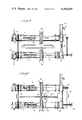
- FIG. 1 is a schematic view of the general arrangement of the apparatus, suitable for use on an off-shore drilling platform,
- FIG. 2 is a cross-sectional view of the apparatus of FIG. 1, taking along lines A-A',
- FIG. 3 is a schematic view of an alternative embodiment of the present invention.
- FIG. 4 is a cross-sectional view of the apparatus of FIG. 1, taken along sectional line B-B',
- FIG. 5 is a general schematic view of the apparatus of the present invention, showing relative material movement
- FIG. 6 is a general schematic view of the apparatus of the present invention, showing relative rotation of the various components of the apparatus.
- apparatus 1 includes upper retort vessel 2 and lower retort vessel 3.
- Upper retort vessel 2 is supported by rotation support bearings 5, whereas lower retort tube 3 is supported by rotation support bearings 6, 7.
- Each set of bearings is supported on suitable journals (not shown).
- upper retort vessel 2 Located inside of upper retort vessel 2 is auger-type conveyor 8, having the ends 9, 10 thereof supported by supporting bushing which are vertically adjustable (not shown).
- lower retort vessel 3 contains auger-type conveyor 11 having the shaft ends 12, 13 thereof supported in vertically adjustable support bushings (not shown).
- the end of upper retort vessel 2 closest to bearing 4 extends into feed box 14 through stuffing box 15.
- Feed inlet 16 is located on top of feed box 14, and contains lead seal fire dampener 17.
- the end of upper retort vessel 2 closest to bushing 5 is received into discharge box 18 and suffing box 19.
- Air eductor 29 maintains a slight vacuum inside of the apparatus to facilitate removal of gases from solids therein.
- Drive gear 30 located on lower retort vessel 3 is driven by a suitable motor (not shown) through gears (not shown) to cause the retort tube 3 to rotate.
- Slave drive 31 causes retort vessel 2 to rotate at the same speed and in the same direction as retort vessel 3.
- the outer end of shaft 13 of auger-type conveyor 11 contains an auger primary drive gear 32, which is driven by a suitable motor (not shown) by suitable gears (not shown), to cause auger 11 to rotate in a direction which is opposite the rotational direction of retort tube 3.
- Slave drive 33 extends between shaft 13 and shaft 10, and causes auger-type conveyor 8 to rotate at the same speed and in the same direction as auger 11.
- Retort vessel 2 is heated by induction heating coil 34, and retort vessel 3 is heated by induction heating coil 35, with induction heating coils 34, 35 connected by suitable leads (not shown) to a source of electricity.
- Each induction heating coil is located around its associated retort vessel, and is supported therefrom by conventional means (not shown).
- Coils 34, 35 are connected by yoke 36, which includes offset yoke segment 37, 38, which are engagable by lip 39 on spocket chain 40.
- Spocket chain 40 extends between spocket 41 and spocket 42, with spocket 42 driven by a suitable motor (not shown).
- the induction heating coils are continuously moved along the length of the retort vessels during operation.
- one or more additional sets of conduction heating coils can be installed on the retort vessels, adjacent stuffing boxes 15 or 19 or 21 or 23.
- Lines 43, 44 are provided to supply carbon dioxide or steam or other inert gas to discharge box 22 or feed box 14, respectively. In case of emergency, the passage of an inert gas through one or both of these lines will extinguish fires or reduce risk of explosion.
- hydrocarbon sniffer “detectors” and thermocouplers are located in discharge box 18, transfer tube 26, feed box 20, and discharge box 22 in order to monitor the hydrocarbon removal from the drill cuttings or other solids being treated.
- Auger-type conveyor 8 has a auger screw 45 mounted on shaft 46, and scratchers 47, suitably of springy airplane wire in the form of a figure 8, are located between the blades of the auger in order to scrape the inside surface of the retort tube to remove additional adherent residual material.
- the arrangement of auger-type conveyor 11 is similar to that of auger-type conveyor 8.
- the apparatus is suitable for use on off-shore oil and gas drilling platforms, wherein space is at a premium.
- the two augers in series ensure substantially complete removal of oil and other hydrocarbons from drill cuttings.
- With the coils traveling along the length of the retort vessels during operation a relatively uniform heat is produced in the materials inside of the vessels so that the hot spots are avoided or minimized.
- the heating be conducted by induction heating coils, as the vessel contents are thereby quickly heated to the desired temperatures and open flames are eliminated, so that risk of fire and/or explosion is minimized.
- the heating should be at least to 350° F. in order to obtain adequate hydrocarbon removal, and should be no greater than 600° F., as above that temperature the danger of fire becomes substantial.
- the vessel contents be heated to a temperature of 400° F. to 450° F. as it has been found that temperatures within this range provide good removal of hydrocarbons from the drill cuttings or other solids, without requiring undue amounts of energy.
- the speed of material travel through the apparatus depends upon the feed rate of incoming material and upon the rotation rate of the vessels and the counter rotating auger contained therein. Normally the vessel and the auger are relatively rotated at a speed of at least 1/5 of a revolution per minute, more preferably at least 1 revolution per minute, most preferably about 2 revolutions per minute. Faster speeds can, of course, be utilized but do not provide any great advantage and consume more energy. The speed should not be so fast that the hold up time of the material in the apparatus is so short that incomplete hydrocarbon removal from the drill cuttings will be achieved, and normally will not exceed 50-80 revolutions per minute.
- the vessel may be rotated slightly faster than the auger.
- induction heating coils In place of induction heating coils, other types of heating can be used as decidedly less preferred embodiments of the invention, including ultrasonic heating, microwave radiation heating, pulse laser beam heating, electrical resistance heating, open flame heating, and the like.
- the retention time of solids traveling through the apparatus of the present invention will vary from about 4 minutes to several days, preferably 5 to 25 minutes.
- the retort vessel diameter can vary from 1/2 foot or even less to a diameter of several feet or even more, but conveniently is within the range of 1-2 feet in internal diameter.
- the length of the vessel or vessels will be determined by the desired retention time of solids in the vessel, as well as the desired feed rate of solids to the vessel. Within these parameters, however, the vessel length can vary widely.
- vessels as short as 5 feet or as long as 30 feet could be, but preferably the vessel will be of a length of 8 to 15 feet. If greater vessel lengths are desired, it is possible to use an additional number of retort vessels, each with it counter-rotating auger-type conveyor therein, in addition to the two such vessels illustrated in FIG. 1.
- the augers 8, 11 in the retort vessels will preferably be eccentrically located in the retort vessel, with the auger center line being located vertically below the retort vessel center line.
- This arrangement will provide for good scraping of the materials on the bottom of the retort vessel, while providing good clearance at other points between the auger and the vessel.
- the auger has a clearance of 1/2 to 1/4 inch, preferably about 1/16 inch, at the bottom of the retort vessel, and a clearance of 1/2 inch or more at the top of the retort vessel.
- a suitable auger may be 14 inches in diameter, with the rotational axis of the auger being located 15/16 inch below the rotation axis of the retort vessel, providing a clearance of 1/16 inch on the bottom of the vessel, and of 1 and 15/16 inches at the top of the vessel.
- the auger, the vessel, or both may be subjected to periodic or continuous vibrations, but this is not normally necessary.
- the vacuum which is exerted upon the interior of apparatus 1 by air eductor 29 can vary within wide limits. Normally a vacuum of at least 0.02 inch of water, preferably about 1 inch of water, will be utilized and much higher vacuum levels, up to 15 or 20 inches of mercury, can be used but are not required.
- FIG. 2 is a cross-sectional view of the apparatus of FIG. 1 or of FIG. 3, taken along the lines B-B', and shows the eccentric placement of auger-type conveyor 11.
- Conveyor 11 includes a shaft 201 and auger screw conveyor blade 202.
- Shaft 201 is located vertically below the axis 203 of the retort vessel 3.
- FIG. 3 illustrates another embodiment of the apparatus of the present invention.
- Apparatus 301 includes upper retort vessel 2' and lower retort vessel 3', each having associated induction heating coil 34' or 35'.
- Apparatus 301 is identical to apparatus 1 of FIG. 1, except for the induction heating coil travel drive.
- Drive gear 302 is turned by a motor (not shown) operating through appropriate gears (not shown), and turns reversing or double cut induction drive helix shaft 303.
- Shaft 303 is supported by helix drive support bearings 304, 305.
- Induction heating coil drive box 306 travels along shaft 303, and is connected by way of arm 307 and 308 to induction heating coil 304' and 305' respectively.
- FIG. 4 represents a cross-sectional view of retort vessel 2 of FIG. 1 or retort vessel 2' of FIG. 3, and illustrates the retention device 401 located at the discharge end of auger-type conveyor blade 45.
- Retention plate 402 is mounted around shaft 10 at the end of blade 45. Slots 403 are formed in plate 402, and are partially blocked by adjustable plate 404. Plate 404 is adjusted by means of adjustable mounting members 405, 406, which extend out of the top of discharge box 18. Knurled adjusting nuts (not shown) on the upper threaded ends of members 405, 406 permit adjustment of plate 404. (For clarity, the ends of members 405, 406, and associated nuts, are not shown in FIGS. 3, 5 or 6).
- FIG. 5 is a schematic illustrating the flow of solid materials in the apparatus of FIG. 1.
- Material enters by way of feed inlet 16 into feed box 14, and then passes through retort vessel 2 under the influence of conveyor 8.
- the material passes into discharge box 18, from which it falls under the force of gravity to transfer tube 26 into feed box 20.
- From feed box 20 material is picked up conveyor 11 and forced through retort vessel 3 to discharge box 22, from which it falls by the force of gravity through discharge line 14.
- FIG. 6 is a schematic representation of the direction of rotation of the various elements of FIG. 3.
- Lower retort vessel 3' is rotated by a motor acting through gears upon drive gear 30', which causes retort vessel 3' to rotate in the indicated direction.
- Retort vessel 2' is caused to rotate in the same direction by way of slave drive 31'.
- Auger primary drive 32' is rotated by a motor operating through suitable gears, and auger primary drive 32' and attached shaft 13' rotate in the indicated direction which is opposite the rotation of retort vessel 3'.
- Shaft 13' in turn rotates auger-type conveyor 11' in the same relative direction, which is in counter rotation to the direction of rotation of the retort vessel 3'.
- shaft 13' causes a rotation of shaft 10', by way of slave drive 33'.
- Shaft 10' rotates in a direction opposite the direction of rotation of retort vessel 2', and in turn causes screw conveyor 8' to rotate in the same direction as shaft 10'.
- sprocket 42 of FIG. 1 causes chain 40, with associated lip 39, to revolve around sprockets 41 and 42.
- Lip 39 pushes the induction heating coils along, acting either on lip 37 or lip 38, so that coils 34, 35 travel back and forth along the length of the respective retort vessels 2, 3.
- the retort vessel diameter and length, as well as the speed of rotation of the retort vessel and the auger-type conveyor, can vary widely depending upon a number of variables, including the feed rate of incoming material, the temperature to which the material being treated is subjected, and the desired material retention time within the apparatus.
- a typical apparatus of FIG. 1 might have retort vessels 10 feet long and 123/4 inches in diameter, having a 12 inch diameter auger located therein.
- the retort vessel might rotate at a speed of 1 revolution per minute in one direction, with the auger rotating at a speed of 1 revolution per minute in the opposite direction.
- the auger may have a clearance of 1/16 to inch at the bottom of the retort vessel, with a clearance of about 11/16 inch at the top of the retort vessel.
Landscapes
- Engineering & Computer Science (AREA)
- Life Sciences & Earth Sciences (AREA)
- Chemical & Material Sciences (AREA)
- Mining & Mineral Resources (AREA)
- General Engineering & Computer Science (AREA)
- Mechanical Engineering (AREA)
- Oil, Petroleum & Natural Gas (AREA)
- Geology (AREA)
- Environmental & Geological Engineering (AREA)
- General Life Sciences & Earth Sciences (AREA)
- Geochemistry & Mineralogy (AREA)
- Wood Science & Technology (AREA)
- Fluid Mechanics (AREA)
- Chemical Kinetics & Catalysis (AREA)
- General Chemical & Material Sciences (AREA)
- Physics & Mathematics (AREA)
- Organic Chemistry (AREA)
- Processing Of Solid Wastes (AREA)
- Physical Or Chemical Processes And Apparatus (AREA)
- Furnace Charging Or Discharging (AREA)
- Drilling And Boring (AREA)
Priority Applications (10)
| Application Number | Priority Date | Filing Date | Title |
|---|---|---|---|
| US06/125,531 US4304609A (en) | 1980-02-28 | 1980-02-28 | Drill cuttings treatment apparatus and method |
| SE8100843A SE8100843L (sv) | 1980-02-28 | 1981-02-06 | Anordning och sett att avlegsna kolveten fran borrningsavfall |
| FR8102895A FR2478805A1 (fr) | 1980-02-28 | 1981-02-13 | Procede et appareil de traitement des debris de forage |
| NO81810490A NO810490L (no) | 1980-02-28 | 1981-02-13 | Anordning for behandling av borekutt og fremgangsmaate ved denne behandling. |
| DE19813106293 DE3106293A1 (de) | 1980-02-28 | 1981-02-20 | "verfahren und vorrichtung zum entfernen von kohlenwasserstoffen aus feststoffen" |
| NL8100887A NL8100887A (nl) | 1980-02-28 | 1981-02-23 | Inrichting en werkwijze voor het behandelen van losgeboord materiaal. |
| DK90381A DK90381A (da) | 1980-02-28 | 1981-02-27 | Fremgangsmaade og apparat til behandling af boremateriale ved olieboringer |
| GB8106302A GB2071138A (en) | 1980-02-28 | 1981-02-27 | Apparatus for treating drill cuttings |
| AU67944/81A AU6794481A (en) | 1980-02-28 | 1981-02-27 | Removal of hydro carbons from drill cuttings |
| US06/297,212 US4453319A (en) | 1980-02-28 | 1981-08-28 | Aqueous drill cutting treatment apparatus and method |
Applications Claiming Priority (1)
| Application Number | Priority Date | Filing Date | Title |
|---|---|---|---|
| US06/125,531 US4304609A (en) | 1980-02-28 | 1980-02-28 | Drill cuttings treatment apparatus and method |
Related Child Applications (1)
| Application Number | Title | Priority Date | Filing Date |
|---|---|---|---|
| US06/297,212 Continuation-In-Part US4453319A (en) | 1980-02-28 | 1981-08-28 | Aqueous drill cutting treatment apparatus and method |
Publications (1)
| Publication Number | Publication Date |
|---|---|
| US4304609A true US4304609A (en) | 1981-12-08 |
Family
ID=22420146
Family Applications (1)
| Application Number | Title | Priority Date | Filing Date |
|---|---|---|---|
| US06/125,531 Expired - Lifetime US4304609A (en) | 1980-02-28 | 1980-02-28 | Drill cuttings treatment apparatus and method |
Country Status (9)
| Country | Link |
|---|---|
| US (1) | US4304609A (da) |
| AU (1) | AU6794481A (da) |
| DE (1) | DE3106293A1 (da) |
| DK (1) | DK90381A (da) |
| FR (1) | FR2478805A1 (da) |
| GB (1) | GB2071138A (da) |
| NL (1) | NL8100887A (da) |
| NO (1) | NO810490L (da) |
| SE (1) | SE8100843L (da) |
Cited By (50)
| Publication number | Priority date | Publication date | Assignee | Title |
|---|---|---|---|---|
| US4453319A (en) * | 1980-02-28 | 1984-06-12 | Morris James B N | Aqueous drill cutting treatment apparatus and method |
| DE3315557A1 (de) * | 1983-04-29 | 1984-10-31 | Dr. Böing GmbH & Co Anlagen und Maschinen KG, 5800 Hagen | Verfahren und einrichtung zum reinigen feinstueckigen gutes von oeligen oder fettigen verunreinigungen, insbesondere zum reinigen mit schneidoel verunreinigter metallspaene |
| US4595422A (en) * | 1984-05-11 | 1986-06-17 | Cds Development, Inc. | Drill cutting disposal system |
| US4599117A (en) * | 1982-02-05 | 1986-07-08 | Luxemburg S Roy | Process for the decontamination of oil-contaminated particulate solids |
| US4654150A (en) * | 1985-08-12 | 1987-03-31 | Associated Oiltools, Inc. | Apparatus and method for removing combustibles from drill cuttings |
| US4836302A (en) * | 1986-12-03 | 1989-06-06 | Heilhecker Joe K | Apparatus and method for removing and recovering oil and/or other oil-based drilling mud additives from drill cuttings |
| US4908104A (en) * | 1988-12-28 | 1990-03-13 | Apv Chemical Machinery Inc. | Method of continuously carbonizing a mixture of primarily organic waste material |
| US4954223A (en) * | 1988-07-29 | 1990-09-04 | Leary Joseph E | Distillation apparatus |
| US5005655A (en) * | 1986-12-03 | 1991-04-09 | Conoco Inc. | Partially halogenated ethane solvent removal of oleophylic materials from mineral particles |
| US5017269A (en) * | 1988-12-28 | 1991-05-21 | Apv Chemical Machinery Inc. | Method of continuously carbonizing primarily organic waste material |
| US5053082A (en) * | 1990-02-28 | 1991-10-01 | Conoco Inc. | Process and apparatus for cleaning particulate solids |
| US5080721A (en) * | 1990-02-28 | 1992-01-14 | Conoco Inc. | Process for cleaning particulate solids |
| US5107874A (en) * | 1990-02-28 | 1992-04-28 | Conoco Inc. | Apparatus for cleaning particulate solids |
| WO1995006093A1 (en) * | 1993-08-20 | 1995-03-02 | Technological Resources Pty. Ltd. | Enhanced hydrocarbon recovery method |
| US5447052A (en) * | 1992-11-23 | 1995-09-05 | Texaco Inc. | Microwave hydrocarbon gas extraction system |
| US5570749A (en) * | 1995-10-05 | 1996-11-05 | Onsite Technology, L.L.C. | Drilling fluid remediation system |
| US5582118A (en) * | 1992-01-25 | 1996-12-10 | Torftech Limited | Removal of organic contaminants from solid particles |
| US5628969A (en) * | 1995-10-18 | 1997-05-13 | Mercury Treatment Alternatives, Inc. | Chemical separation and reaction apparatus |
| CN1066459C (zh) * | 1994-11-14 | 2001-05-30 | 巴斯福股份公司 | 借助包括于橡胶中并热分解时形成游离基的基团制备橡胶改性模塑材料的方法 |
| US6440312B1 (en) * | 2000-05-02 | 2002-08-27 | Kai Technologies, Inc. | Extracting oil and water from drill cuttings using RF energy |
| WO2003008651A1 (en) * | 2001-07-20 | 2003-01-30 | Kimmel's Coal And Recycling, Inc/Ghent Operation | Steel making material recycling system |
| US20030107174A1 (en) * | 2001-12-11 | 2003-06-12 | Loewenstein David Allen | Poker game |
| US20030136747A1 (en) * | 2002-01-18 | 2003-07-24 | Wood Bradford Russell | Soil cleaning systems and methods |
| US20050279715A1 (en) * | 2002-01-18 | 2005-12-22 | Strong Gary S | Thermal drill cuttings treatment with weir system |
| US20060011386A1 (en) * | 2003-04-16 | 2006-01-19 | Particle Drilling Technologies, Inc. | Impact excavation system and method with improved nozzle |
| US20060180350A1 (en) * | 2003-04-16 | 2006-08-17 | Particle Drilling Technologies, Inc. | Impact excavation system and method with particle trap |
| US20060191717A1 (en) * | 2003-04-16 | 2006-08-31 | Particle Drilling Technologies, Inc. | Impact excavation system and method with two-stage inductor |
| US7383896B2 (en) | 2003-04-16 | 2008-06-10 | Particle Drilling Technologies, Inc. | Impact excavation system and method with particle separation |
| US20090038856A1 (en) * | 2007-07-03 | 2009-02-12 | Particle Drilling Technologies, Inc. | Injection System And Method |
| US7503407B2 (en) | 2003-04-16 | 2009-03-17 | Particle Drilling Technologies, Inc. | Impact excavation system and method |
| US20090200084A1 (en) * | 2004-07-22 | 2009-08-13 | Particle Drilling Technologies, Inc. | Injection System and Method |
| US20090200080A1 (en) * | 2003-04-16 | 2009-08-13 | Tibbitts Gordon A | Impact excavation system and method with particle separation |
| US20100145129A1 (en) * | 2002-06-18 | 2010-06-10 | Awazel International Company W.L.L. | Extraction methods and apparatus |
| US20100147670A1 (en) * | 2007-05-25 | 2010-06-17 | Gebr. Lodige Maschinenbau Gmbh | Method and device for thermally disintegrating a starting material using foreign particles |
| US7757786B2 (en) | 2003-04-16 | 2010-07-20 | Pdti Holdings, Llc | Impact excavation system and method with injection system |
| US7798249B2 (en) | 2003-04-16 | 2010-09-21 | Pdti Holdings, Llc | Impact excavation system and method with suspension flow control |
| US7980326B2 (en) | 2007-11-15 | 2011-07-19 | Pdti Holdings, Llc | Method and system for controlling force in a down-hole drilling operation |
| US7987928B2 (en) | 2007-10-09 | 2011-08-02 | Pdti Holdings, Llc | Injection system and method comprising an impactor motive device |
| US8037950B2 (en) | 2008-02-01 | 2011-10-18 | Pdti Holdings, Llc | Methods of using a particle impact drilling system for removing near-borehole damage, milling objects in a wellbore, under reaming, coring, perforating, assisting annular flow, and associated methods |
| US20120027662A1 (en) * | 2010-07-27 | 2012-02-02 | Heritage Environmental Services, Llc | Induction heated gasifier |
| US20120024687A1 (en) * | 2010-07-27 | 2012-02-02 | Heritage Environmental Services, Llc | Induction heated screw |
| US8342265B2 (en) | 2003-04-16 | 2013-01-01 | Pdti Holdings, Llc | Shot blocking using drilling mud |
| US8485279B2 (en) | 2009-04-08 | 2013-07-16 | Pdti Holdings, Llc | Impactor excavation system having a drill bit discharging in a cross-over pattern |
| CN105041214A (zh) * | 2015-07-09 | 2015-11-11 | 四川川庆石油钻采科技有限公司 | 一种适用于粒子钻井的双注入泵连续注入方法 |
| US10220758B2 (en) * | 2015-02-25 | 2019-03-05 | Recover Energy Services Inc. | Heated drill cuttings transport vessel |
| US20200141220A1 (en) * | 2018-11-03 | 2020-05-07 | Taurus Investment Group Inc. | Transportable drilling fluid processing system |
| CN115751916A (zh) * | 2022-11-01 | 2023-03-07 | 长江大学 | 一种含油钻屑片状激光束快速分离装置 |
| US11970917B2 (en) | 2019-11-22 | 2024-04-30 | Elavo Energy Solutions Ltd. | System and method for removing drilling fluid from drill cuttings using direct heat |
| US12098602B2 (en) | 2019-11-22 | 2024-09-24 | Elavo Cleantech Ltd. | System and method for removing drilling fluid from drill cuttings using direct heat |
| US12623162B2 (en) | 2019-11-22 | 2026-05-12 | Elavo Energy Solutions Ltd. | System and method for removing drilling fluid from drill cuttings using direct heat |
Families Citing this family (4)
| Publication number | Priority date | Publication date | Assignee | Title |
|---|---|---|---|---|
| US4639258A (en) * | 1983-10-14 | 1987-01-27 | Leon E. Roy | Single pass mud rejuvenation system and method |
| NO155832C (no) * | 1984-10-08 | 1987-06-10 | Olav Ellingsen | Fremgangsmaate til utvinning av olje fra slam bestaaende av finfordelte uorganiske og/eller organiske partikler og olje og vann eller andre fordampbare vaesker. |
| GB201004535D0 (en) | 2010-03-18 | 2010-05-05 | William Curle Developments Ltd | Solids heat exchanger for drill cuttings |
| GB201400983D0 (en) * | 2014-01-21 | 2014-03-05 | Nov Downhole Eurasia Ltd | Extraction of hydrocarbons |
Citations (12)
| Publication number | Priority date | Publication date | Assignee | Title |
|---|---|---|---|---|
| US1604253A (en) * | 1925-02-14 | 1926-10-26 | Clarence E Barnhart | Oil-shale retort |
| US1712083A (en) * | 1922-06-28 | 1929-05-07 | Koppers Heinrich | Apparatus for distilling bituminous substances |
| US1810828A (en) * | 1927-05-16 | 1931-06-16 | Coal Carbonization Company | Method of carbonizing coal |
| US1884379A (en) * | 1930-05-03 | 1932-10-25 | Allis Chalmers Mfg Co | Carbonization device |
| US2078914A (en) * | 1933-10-28 | 1937-04-27 | Banks O Daubert | Distilling apparatus |
| US2620286A (en) * | 1948-09-03 | 1952-12-02 | Morris R Shaw | Removing carbonaceous deposits from still tubes |
| US2722589A (en) * | 1950-11-30 | 1955-11-01 | Ohio Crankshaft Co | Method and apparatus for uniformly heating intermittently moving metallic material |
| US3616266A (en) * | 1969-04-29 | 1971-10-26 | Oil Shale Corp | Horizontal retort with solid heat transfer medium |
| US3705285A (en) * | 1971-11-05 | 1972-12-05 | Growth Intern Inc | Mobile apparatus for the induction heating of metal ingots |
| US4098648A (en) * | 1975-03-25 | 1978-07-04 | Philipp Kraemer | Rotary separating and extracting devices |
| US4139462A (en) * | 1976-07-12 | 1979-02-13 | Dresser Industries, Inc. | Method for thermally treating oil well drill cuttings |
| US4210491A (en) * | 1976-11-01 | 1980-07-01 | Tosco Corporation | Method and apparatus for retorting a substance containing organic matter |
-
1980
- 1980-02-28 US US06/125,531 patent/US4304609A/en not_active Expired - Lifetime
-
1981
- 1981-02-06 SE SE8100843A patent/SE8100843L/ not_active Application Discontinuation
- 1981-02-13 FR FR8102895A patent/FR2478805A1/fr not_active Withdrawn
- 1981-02-13 NO NO81810490A patent/NO810490L/no unknown
- 1981-02-20 DE DE19813106293 patent/DE3106293A1/de not_active Withdrawn
- 1981-02-23 NL NL8100887A patent/NL8100887A/nl not_active Application Discontinuation
- 1981-02-27 GB GB8106302A patent/GB2071138A/en not_active Withdrawn
- 1981-02-27 AU AU67944/81A patent/AU6794481A/en not_active Abandoned
- 1981-02-27 DK DK90381A patent/DK90381A/da unknown
Patent Citations (12)
| Publication number | Priority date | Publication date | Assignee | Title |
|---|---|---|---|---|
| US1712083A (en) * | 1922-06-28 | 1929-05-07 | Koppers Heinrich | Apparatus for distilling bituminous substances |
| US1604253A (en) * | 1925-02-14 | 1926-10-26 | Clarence E Barnhart | Oil-shale retort |
| US1810828A (en) * | 1927-05-16 | 1931-06-16 | Coal Carbonization Company | Method of carbonizing coal |
| US1884379A (en) * | 1930-05-03 | 1932-10-25 | Allis Chalmers Mfg Co | Carbonization device |
| US2078914A (en) * | 1933-10-28 | 1937-04-27 | Banks O Daubert | Distilling apparatus |
| US2620286A (en) * | 1948-09-03 | 1952-12-02 | Morris R Shaw | Removing carbonaceous deposits from still tubes |
| US2722589A (en) * | 1950-11-30 | 1955-11-01 | Ohio Crankshaft Co | Method and apparatus for uniformly heating intermittently moving metallic material |
| US3616266A (en) * | 1969-04-29 | 1971-10-26 | Oil Shale Corp | Horizontal retort with solid heat transfer medium |
| US3705285A (en) * | 1971-11-05 | 1972-12-05 | Growth Intern Inc | Mobile apparatus for the induction heating of metal ingots |
| US4098648A (en) * | 1975-03-25 | 1978-07-04 | Philipp Kraemer | Rotary separating and extracting devices |
| US4139462A (en) * | 1976-07-12 | 1979-02-13 | Dresser Industries, Inc. | Method for thermally treating oil well drill cuttings |
| US4210491A (en) * | 1976-11-01 | 1980-07-01 | Tosco Corporation | Method and apparatus for retorting a substance containing organic matter |
Cited By (68)
| Publication number | Priority date | Publication date | Assignee | Title |
|---|---|---|---|---|
| US4453319A (en) * | 1980-02-28 | 1984-06-12 | Morris James B N | Aqueous drill cutting treatment apparatus and method |
| US4599117A (en) * | 1982-02-05 | 1986-07-08 | Luxemburg S Roy | Process for the decontamination of oil-contaminated particulate solids |
| DE3315557A1 (de) * | 1983-04-29 | 1984-10-31 | Dr. Böing GmbH & Co Anlagen und Maschinen KG, 5800 Hagen | Verfahren und einrichtung zum reinigen feinstueckigen gutes von oeligen oder fettigen verunreinigungen, insbesondere zum reinigen mit schneidoel verunreinigter metallspaene |
| US4595422A (en) * | 1984-05-11 | 1986-06-17 | Cds Development, Inc. | Drill cutting disposal system |
| US4654150A (en) * | 1985-08-12 | 1987-03-31 | Associated Oiltools, Inc. | Apparatus and method for removing combustibles from drill cuttings |
| US5005655A (en) * | 1986-12-03 | 1991-04-09 | Conoco Inc. | Partially halogenated ethane solvent removal of oleophylic materials from mineral particles |
| US4836302A (en) * | 1986-12-03 | 1989-06-06 | Heilhecker Joe K | Apparatus and method for removing and recovering oil and/or other oil-based drilling mud additives from drill cuttings |
| US4954223A (en) * | 1988-07-29 | 1990-09-04 | Leary Joseph E | Distillation apparatus |
| US4908104A (en) * | 1988-12-28 | 1990-03-13 | Apv Chemical Machinery Inc. | Method of continuously carbonizing a mixture of primarily organic waste material |
| US5017269A (en) * | 1988-12-28 | 1991-05-21 | Apv Chemical Machinery Inc. | Method of continuously carbonizing primarily organic waste material |
| US5053082A (en) * | 1990-02-28 | 1991-10-01 | Conoco Inc. | Process and apparatus for cleaning particulate solids |
| US5080721A (en) * | 1990-02-28 | 1992-01-14 | Conoco Inc. | Process for cleaning particulate solids |
| US5107874A (en) * | 1990-02-28 | 1992-04-28 | Conoco Inc. | Apparatus for cleaning particulate solids |
| US5582118A (en) * | 1992-01-25 | 1996-12-10 | Torftech Limited | Removal of organic contaminants from solid particles |
| US5447052A (en) * | 1992-11-23 | 1995-09-05 | Texaco Inc. | Microwave hydrocarbon gas extraction system |
| WO1995006093A1 (en) * | 1993-08-20 | 1995-03-02 | Technological Resources Pty. Ltd. | Enhanced hydrocarbon recovery method |
| CN1066459C (zh) * | 1994-11-14 | 2001-05-30 | 巴斯福股份公司 | 借助包括于橡胶中并热分解时形成游离基的基团制备橡胶改性模塑材料的方法 |
| US5570749A (en) * | 1995-10-05 | 1996-11-05 | Onsite Technology, L.L.C. | Drilling fluid remediation system |
| US5628969A (en) * | 1995-10-18 | 1997-05-13 | Mercury Treatment Alternatives, Inc. | Chemical separation and reaction apparatus |
| US6440312B1 (en) * | 2000-05-02 | 2002-08-27 | Kai Technologies, Inc. | Extracting oil and water from drill cuttings using RF energy |
| US20070256516A1 (en) * | 2001-07-20 | 2007-11-08 | Mcclintock Willard K | Steel making material recycling system |
| WO2003008651A1 (en) * | 2001-07-20 | 2003-01-30 | Kimmel's Coal And Recycling, Inc/Ghent Operation | Steel making material recycling system |
| US20030107174A1 (en) * | 2001-12-11 | 2003-06-12 | Loewenstein David Allen | Poker game |
| US20040222590A9 (en) * | 2001-12-11 | 2004-11-11 | Loewenstein David Allen | Poker game |
| US20050279715A1 (en) * | 2002-01-18 | 2005-12-22 | Strong Gary S | Thermal drill cuttings treatment with weir system |
| US20030136747A1 (en) * | 2002-01-18 | 2003-07-24 | Wood Bradford Russell | Soil cleaning systems and methods |
| US7306057B2 (en) | 2002-01-18 | 2007-12-11 | Varco I/P, Inc. | Thermal drill cuttings treatment with weir system |
| US20120145597A1 (en) * | 2002-06-18 | 2012-06-14 | Awazel International Company W.L.L. | Extraction methods and apparatus |
| US20100145129A1 (en) * | 2002-06-18 | 2010-06-10 | Awazel International Company W.L.L. | Extraction methods and apparatus |
| US20090200080A1 (en) * | 2003-04-16 | 2009-08-13 | Tibbitts Gordon A | Impact excavation system and method with particle separation |
| US7383896B2 (en) | 2003-04-16 | 2008-06-10 | Particle Drilling Technologies, Inc. | Impact excavation system and method with particle separation |
| US7398839B2 (en) * | 2003-04-16 | 2008-07-15 | Particle Drilling Technologies, Inc. | Impact excavation system and method with particle trap |
| US8342265B2 (en) | 2003-04-16 | 2013-01-01 | Pdti Holdings, Llc | Shot blocking using drilling mud |
| US7503407B2 (en) | 2003-04-16 | 2009-03-17 | Particle Drilling Technologies, Inc. | Impact excavation system and method |
| US20060011386A1 (en) * | 2003-04-16 | 2006-01-19 | Particle Drilling Technologies, Inc. | Impact excavation system and method with improved nozzle |
| US20060191717A1 (en) * | 2003-04-16 | 2006-08-31 | Particle Drilling Technologies, Inc. | Impact excavation system and method with two-stage inductor |
| US20060180350A1 (en) * | 2003-04-16 | 2006-08-17 | Particle Drilling Technologies, Inc. | Impact excavation system and method with particle trap |
| US8162079B2 (en) | 2003-04-16 | 2012-04-24 | Pdti Holdings, Llc | Impact excavation system and method with injection system |
| US7757786B2 (en) | 2003-04-16 | 2010-07-20 | Pdti Holdings, Llc | Impact excavation system and method with injection system |
| US7793741B2 (en) | 2003-04-16 | 2010-09-14 | Pdti Holdings, Llc | Impact excavation system and method with injection system |
| US7798249B2 (en) | 2003-04-16 | 2010-09-21 | Pdti Holdings, Llc | Impact excavation system and method with suspension flow control |
| US7909116B2 (en) | 2003-04-16 | 2011-03-22 | Pdti Holdings, Llc | Impact excavation system and method with improved nozzle |
| US8113300B2 (en) | 2004-07-22 | 2012-02-14 | Pdti Holdings, Llc | Impact excavation system and method using a drill bit with junk slots |
| US20090200084A1 (en) * | 2004-07-22 | 2009-08-13 | Particle Drilling Technologies, Inc. | Injection System and Method |
| US7997355B2 (en) | 2004-07-22 | 2011-08-16 | Pdti Holdings, Llc | Apparatus for injecting impactors into a fluid stream using a screw extruder |
| US8414743B2 (en) * | 2007-05-25 | 2013-04-09 | Gebr. Lodige Maschinebau GmbH | Method and device for thermally disintegrating a starting material using foreign particles |
| US20100147670A1 (en) * | 2007-05-25 | 2010-06-17 | Gebr. Lodige Maschinenbau Gmbh | Method and device for thermally disintegrating a starting material using foreign particles |
| US20090038856A1 (en) * | 2007-07-03 | 2009-02-12 | Particle Drilling Technologies, Inc. | Injection System And Method |
| US7987928B2 (en) | 2007-10-09 | 2011-08-02 | Pdti Holdings, Llc | Injection system and method comprising an impactor motive device |
| US7980326B2 (en) | 2007-11-15 | 2011-07-19 | Pdti Holdings, Llc | Method and system for controlling force in a down-hole drilling operation |
| US8353367B2 (en) | 2008-02-01 | 2013-01-15 | Gordon Tibbitts | Methods of using a particle impact drilling system for removing near-borehole damage, milling objects in a wellbore, under reaming, coring perforating, assisting annular flow, and associated methods |
| US8037950B2 (en) | 2008-02-01 | 2011-10-18 | Pdti Holdings, Llc | Methods of using a particle impact drilling system for removing near-borehole damage, milling objects in a wellbore, under reaming, coring, perforating, assisting annular flow, and associated methods |
| US8186456B2 (en) | 2008-02-01 | 2012-05-29 | Pdti Holdings, Llc | Methods of using a particle impact drilling system for removing near-borehole damage, milling objects in a wellbore, under reaming, coring, perforating, assisting annular flow, and associated methods |
| US8353366B2 (en) | 2008-02-01 | 2013-01-15 | Gordon Tibbitts | Methods of using a particle impact drilling system for removing near-borehole damage, milling objects in a wellbore, under reaming, coring, perforating, assisting annular flow, and associated methods |
| US8485279B2 (en) | 2009-04-08 | 2013-07-16 | Pdti Holdings, Llc | Impactor excavation system having a drill bit discharging in a cross-over pattern |
| US8945350B2 (en) * | 2010-07-27 | 2015-02-03 | Heritage Environmental Services Llc | Induction heated screw |
| US20120027662A1 (en) * | 2010-07-27 | 2012-02-02 | Heritage Environmental Services, Llc | Induction heated gasifier |
| US20120024687A1 (en) * | 2010-07-27 | 2012-02-02 | Heritage Environmental Services, Llc | Induction heated screw |
| US8945351B2 (en) * | 2010-07-27 | 2015-02-03 | Heritage Environmental Services Llc | Induction heated gasifier |
| WO2012015815A3 (en) * | 2010-07-27 | 2012-05-31 | Heritage Environmental Services, Llc | Induction heated screw |
| US10220758B2 (en) * | 2015-02-25 | 2019-03-05 | Recover Energy Services Inc. | Heated drill cuttings transport vessel |
| CN105041214A (zh) * | 2015-07-09 | 2015-11-11 | 四川川庆石油钻采科技有限公司 | 一种适用于粒子钻井的双注入泵连续注入方法 |
| WO2017005216A1 (zh) * | 2015-07-09 | 2017-01-12 | 四川川庆石油钻采科技有限公司 | 一种适用于粒子钻井的双注入泵连续注入方法 |
| US20200141220A1 (en) * | 2018-11-03 | 2020-05-07 | Taurus Investment Group Inc. | Transportable drilling fluid processing system |
| US11970917B2 (en) | 2019-11-22 | 2024-04-30 | Elavo Energy Solutions Ltd. | System and method for removing drilling fluid from drill cuttings using direct heat |
| US12098602B2 (en) | 2019-11-22 | 2024-09-24 | Elavo Cleantech Ltd. | System and method for removing drilling fluid from drill cuttings using direct heat |
| US12623162B2 (en) | 2019-11-22 | 2026-05-12 | Elavo Energy Solutions Ltd. | System and method for removing drilling fluid from drill cuttings using direct heat |
| CN115751916A (zh) * | 2022-11-01 | 2023-03-07 | 长江大学 | 一种含油钻屑片状激光束快速分离装置 |
Also Published As
| Publication number | Publication date |
|---|---|
| DK90381A (da) | 1981-08-29 |
| FR2478805A1 (fr) | 1981-09-25 |
| SE8100843L (sv) | 1981-08-29 |
| NL8100887A (nl) | 1981-10-01 |
| DE3106293A1 (de) | 1982-02-18 |
| NO810490L (no) | 1982-03-01 |
| GB2071138A (en) | 1981-09-16 |
| AU6794481A (en) | 1981-09-03 |
Similar Documents
| Publication | Publication Date | Title |
|---|---|---|
| GB2071138A (en) | Apparatus for treating drill cuttings | |
| US4453319A (en) | Aqueous drill cutting treatment apparatus and method | |
| US4412889A (en) | Pyrolysis reaction apparatus | |
| CA2731553C (en) | Apparatus and method for facilitating separation of hydrocarbons from hydrocarbon laden drill cuttings produced in the drilling of wellbores | |
| US4606283A (en) | System for extracting contaminants and hydrocarbons from cuttings waste in oil well drilling | |
| US9073104B2 (en) | Drill cuttings treatment systems | |
| US5242245A (en) | Method and apparatus for vacuum enhanced thermal desorption of hydrocarbon and other contaminants from soils | |
| US4649655A (en) | Drilling mud dehydration system | |
| GB1575576A (en) | Removing volatiles from drill cuttings | |
| US5342421A (en) | Pyrolytic gas treatment system | |
| WO2020237393A1 (en) | Thermal remediation system and process | |
| US4313785A (en) | Method and apparatus for treating waste rock cuttings | |
| US20090113749A1 (en) | High Efficiency Liquid Solid Separator | |
| US5997288A (en) | Apparatus for thermal removal of surface and inherent moisture and limiting rehydration in high moisture coals | |
| US4900401A (en) | Continuous pyrolysis system for tire shreds | |
| KR100303707B1 (ko) | 탄화수소화합물의기화및분해방법및이를수행하는장치 | |
| US5704557A (en) | Method and apparatus for treatment of organic waste material | |
| US20140363234A1 (en) | Apparatus and method for soil remediation | |
| EP3347436B1 (en) | Flash pyrolysis reactor | |
| GB2144836A (en) | Improvements in or relating to a pyrolysis reaction and apparatus | |
| US4654150A (en) | Apparatus and method for removing combustibles from drill cuttings | |
| US3469329A (en) | Method and apparatus for thermally drying fine granular material or mud,especially highly sticky pond mud | |
| US1921993A (en) | Apparatus for low temperature carbonization | |
| BRPI0518355B1 (pt) | Método de correção de solo contaminado com hidrocarbonetos polihalogenados | |
| US1498917A (en) | Apparatus for the distillation of carbonaceous materials |
Legal Events
| Date | Code | Title | Description |
|---|---|---|---|
| STCF | Information on status: patent grant |
Free format text: PATENTED CASE |