US4342154A - Measuring bridge - Google Patents
Measuring bridge Download PDFInfo
- Publication number
- US4342154A US4342154A US06/145,322 US14532280A US4342154A US 4342154 A US4342154 A US 4342154A US 14532280 A US14532280 A US 14532280A US 4342154 A US4342154 A US 4342154A
- Authority
- US
- United States
- Prior art keywords
- measuring
- bar
- vehicle
- vehicles
- track
- Prior art date
- Legal status (The legal status is an assumption and is not a legal conclusion. Google has not performed a legal analysis and makes no representation as to the accuracy of the status listed.)
- Expired - Lifetime
Links
- 238000005452 bending Methods 0.000 claims abstract description 4
- 238000010276 construction Methods 0.000 description 3
- 238000000034 method Methods 0.000 description 2
- 238000004873 anchoring Methods 0.000 description 1
- 238000011161 development Methods 0.000 description 1
- 230000018109 developmental process Effects 0.000 description 1
- 238000006073 displacement reaction Methods 0.000 description 1
- 230000002349 favourable effect Effects 0.000 description 1
- 238000005096 rolling process Methods 0.000 description 1
Images


Classifications
-
- G—PHYSICS
- G01—MEASURING; TESTING
- G01B—MEASURING LENGTH, THICKNESS OR SIMILAR LINEAR DIMENSIONS; MEASURING ANGLES; MEASURING AREAS; MEASURING IRREGULARITIES OF SURFACES OR CONTOURS
- G01B5/00—Measuring arrangements characterised by the use of mechanical techniques
- G01B5/24—Measuring arrangements characterised by the use of mechanical techniques for measuring angles or tapers; for testing the alignment of axes
-
- G—PHYSICS
- G01—MEASURING; TESTING
- G01B—MEASURING LENGTH, THICKNESS OR SIMILAR LINEAR DIMENSIONS; MEASURING ANGLES; MEASURING AREAS; MEASURING IRREGULARITIES OF SURFACES OR CONTOURS
- G01B5/00—Measuring arrangements characterised by the use of mechanical techniques
- G01B5/0002—Arrangements for supporting, fixing or guiding the measuring instrument or the object to be measured
Definitions
- the invention concerns a measuring bridge for determining the orientation of reference points on the body or frame of motor vehicles, having at least one essentially vertical and longitudinally variable measuring adaptor which, being attached to at least one measuring vehicle, is adjustable and selectively determinable in the longitudinal direction of a vehicle to be measured, and which is adjustable and selectively determinable transversely to such vehicle.
- Measuring bridges of this type which in particular can serve, in conjunction with a straightening device for the straightening of damaged motor vehicles, to determine the extent of distortions of body and frame, as well as to continually trace and measure the repair of such distortions during straightening, are described U.S. Pat. Nos. 4,055,061 and 4,174,623.
- These known measuring bridges consist mainly of a rectangular frame with three spans, such spans being connected with each other by means of several crossbars; the lateral span surfaces facing each other are equipped with guides, along which the measuring vehicles can be adjusted in the longitudinal direction of the frame.
- measuring vehicles run transversely to, and between, the spans, and they have upper portions which can be adjusted transversely to the spans and are in turn the supports for vertical running measuring adaptors.
- the frames are placed below, and parallel to the longitudinal direction of, a motor vehicle to be measured, and the measuring adaptors are adjustable in conjunction with the respective measuring vehicles in the longitudinal direction of the motor vehicle, and in conjunction with the upper portions of the measuring vehicle they are adjustable in a transverse direction.
- the measuring adaptors themselves are adjustable in their length; thus they can follow any position changes during the straightening operation having a reference point on the motor vehicle with which (reference point) the respective measuring adaptor is connected at its free end.
- the object of the invention is the design of a measuring bridge of the above-mentioned type so that the bridge, with increased measuring precision and easier operation, permits easier access to all parts of the motor vehicle and can be operated in a simple manner with a number and type of measuring vehicles and measuring adaptors that have maximum suitability for each respective application.
- the invention accomplishes the solution of the assigned problem with a single, bending-resistant measuring bar, adjustable below the motor vehicle to the latter's longitudinal direction, which is equipped along two opposite longitudinal sides with at least one each track, which serve as guides and mounting supports for measuring vehicles carrying measuring adaptors.
- the measuring bridge of the invention is characterized by high torsion resistance, which in turn provides the basis for good measuring accuracy.
- the single measuring bar of the invention's measuring bridge requires only a minimum of space for the storage of the measuring bridge, as well as for its use below a motor vehicle which is to be measured and possibly straightened; besides, the single bar results in considerably less weight for the entire measuring bridge. On the one hand, this offers advantages in storing and transporting the measuring bridge; on the other hand, it results in free accessibility of the motor vehicle for connection to a straightening device and the actual straightening work.
- the invention's measuring bridge permits any adjustment of the measuring vehicles along the measuring bar and their easy exchange for adaption to each respective measuring problem, as well as easy adjustment of the measuring bridge as a whole.
- the adjustment procedure for aligning the measuring bridge with the motor vehicle is very simple, just as the handling of the invention's measuring bridge in general requires only little power and labor, so that the bridge can be prepared for operation by a single man in a short time.
- Another important feature of the invention is the easy access to the adjusting elements at the various bearings for the rollers that are used to adjust the individual components relative to each other; this permits simple adjustment of these components and consequently increased measuring accuracy.
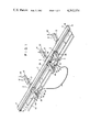
- FIG. 1 a perspective total view of a measuring bridge according to the invention
- FIG. 2 the measuring bar of the measuring bridge in FIG. 1 with support plates for measuring vehicles on both sides in a transverse section with a larger scale
- FIG. 3 a measuring vehicle of the measuring bridge from FIG. 1 in a lateral view, with attached support plate, in a larger scale
- FIG. 4 the measuring vehicle from FIG. 3 in a transverse section in a larger scale
- FIG. 5 one end of the measuring bar of the measuring bridge from FIG. 1 in a transverse section (a), a lateral view (b) and an interior plan view (c).
- the measuring bridge shown in FIG. 1 has as its main component a horizontally running measuring bar 1, on which a total of six measuring vehicles 2, each on a support plate 3, are movable in the longitudinal direction of the measuring bar; three measuring vehicles are located on one side of the bar, and three on the other side; each carries a vertical measuring adaptor 40.
- the bearing support for the measuring bridge in FIG. 1 is formed by a pair of horizontally running bearing rails 44, which support the movable measuring bridge; the bearing rails allow freedom of movement for the measuring bridge not only in its longitudinal direction, but in a limited fashion also transversely to it, so that the measuring bar 1 can be easily adjusted to the longitudinal direction of a motor vehicle to be measured.
- the measuring bar has a box-type profile.
- This profile essentially has the shape of a rectangle with the wide sides running horizontally and the narrow sides 11 running vertically; at their upper and lower outer edges, the narrow sides are pulled inward in such way that two each tracks 12 result, which together enclose a right angle and are inclined horizontally and vertically at an angle of ca. 45°; the outside contours of these tracks create the shape of an L at the four corners of the box-type profile.
- the narrow sides 11 of the measuring bar 1 have at their center one each groove 13, open to the outside, serving as the receptacle for a measuring tape 14, with which the position of the measuring vehicles 2 along the measuring bar 1 can be determined.
- this tape 14 By connecting both ends at a connecting point 15 (see FIG. 5), this tape 14 is continuous and runs at both ends 17 of the measuring bar 1 over guide rollers 16, as is also shown in FIG. 5. In this way the measuring tape 14 can be moved along the measuring bar 1 in such a manner that the zero point of its scale can be placed at a desired point along the measuring bar 1.
- the box-type profile of the measuring bar 1 is closed off at its two ends 17 by a cover plate 18; besides, in order to facilitate the handling and transportation, the measuring bar 1 has one each handle 19 at both ends, as can best be seen in FIG. 1.
- the tracks 12 at the upper and lower edge of the narrow sides 11 of the measuring bar 1 serve as guides and, at the same time, mounting supports for the support plates 3, via which the measuring vehicles 2 are connected with the measuring bar 1.
- the profile of the support plates 3 has the shape of a C, whose open side faces the measuring bar 1, and which overlaps at its ends into a lower, respectively upper, track 12.
- the ends of the support plates 3 contain recesses for the mounting of bearings 32 for the rollers 31; the axles of the rollers run vertically to each other in such a way that the rollers 31 are arranged in pairs at the one and the other track 12 of an L at one of the corners of the box-type profile of the measuring bar 1, so that they can roll on these tracks 12 along the longitudinal direction of the measuring bar 1.
- the bearings 32 for the rollers 31 have been provided with adjusting screws 33, which are accessible from the outside, so that the respective adjustments can be made easily.
- the support plates 3 In the center of their C-profile the support plates 3 have, at their outer side facing away from the measuring bar 1, support bolts 34, which protrude horizontally to the outside; these support bolts 34 serve as mounting components for connecting a support plate 3 with its measuring vehicle 2.
- the upper support bolts 34 are designed to act together with a nut located at the inside of the C-profile of the respective support plate 3 to enable the exact adjustment of the supports bolts 34 - see FIG. 2.
- Each of the support bolts 34 has an outside thread at its free outer end, so that mounting nuts 37 can be screwed on the support bolts 34 as shown in FIG. 3, in order to create a detachable connection between the measuring vehicle 2 and its support plate 3.
- the measuring vehicle 2 can now be moved over the rollers 31 along the tracks 12 at the narrow sides 11 of the measuring bar 1 in the longitudinal direction of the measuring bar 1; a set screw 36, shown in FIG. 3, which runs longitudinally through the measuring vehicle 2 and also penetrates the appurtenant support plate 3, permits the locking of the measuring vehicle 2 and the appurtenant support plate 3 at any point along the measuring bar 1.
- each of the measuring vehicles 2 of the measuring bridge shown in FIG. 1 consists of a lower support 21 and an upper vehicle 22; this upper vehicle 22 can be moved in the longitudinal direction of the measuring vehicle 2 and thus traversely to the operating position of the measuring bar 1, relative to its support 21; this is shown in varying degrees for the individual measuring vehicles 2 in FIG. 1.
- the support 21, which has the shape of a U-profile facing downward, has in the area of its two upper outer edges two each tracks 23, which together form a right angle; these tracks 23 form at the outer face of the support 21, at each of the two upper outer edges of the support 21, the shape of an L, the shanks of which are inclined toward the horizontal and the vertical at an angle of ca. 45° (FIG. 4).
- These tracks 23 serve as guides and mounting supports for the upper vehicle 22, which is supported on the tracks 23 by means of rollers 24, whose axles run vertically to one another.
- the profile of the upper vehicle 22 has the shape of a C, whose open end faces and overlaps the support 21.
- the rollers 24 are supported by bearings 25, which are equipped with adjusting screws 26 for exact adjustment of the rollers 24 of the upper vehicle 22 relative to the tracks 23 at the support 21.
- the adjusting screws are accessible from the outside, which very much facilitates the adjustment work.
- the upper vehicle 22 can be moved with the rollers 24 along tracks 23 at support 21 in the longitudinal direction of the respective measuring vehicle 2, and thus transversely to the measuring bar 1. As seen in FIG.
- a set screw 29 makes it possible to lock the upper vehicle 22 on the appurtenant support 21, with any longitudinal movement as desired.
- measuring scales 27 are provided at both lateral edges of the upper vehicle 22. These scales act in conjunction with indicators 28, which are permanently attached to the support 21.
- a measuring adaptor 40 plugged into an upper vehicle 22 in this manner, can be moved together with this upper vehicle 22 transversely to the measuring bar 1; together with the respective measuring vehicle 2 it can be adjusted in the longitudinal direction of the measuring bar 1 and located at a desired point. Since the measuring adaptors are also adjustable in their length, their ends can be used to mark the position of reference points on a motor vehicle, and to trace changes in the position of these reference points during the course of straightening work being done on this vehicle.
- bearing cylinders 42 are placed below some of the measuring vehicles 2 of the measuring bridge; these bearing cylinders 42 serve to support the respective measuring vehicles 2 and the measuring bar 1 connected to the measuring vehicles on the support rails 44.
- the bearing cylinders 42 as shown in FIG. 3, are attached to the supporting member 21 of the respective measuring vehicles by means of screws, and they each contain a piston which can move downward; a bearing roller 43 is located at the lower end of the piston.
- the entire measuring bridge as shown in FIG. 1 can be moved with the bearing rollers 43 at the various bearing cylinders 42 along the support rails 44 underneath.
- the downward movement of the pistons from the bearing cylinders 42 is achieved by pneumatic or hydraulic drive; the respective measuring vehicles 2 are equipped with connections 46 for pressure media lines 45, through which the respective pressure medium can fed to the bearing cylinders 42.
- pressure regulators 47 are inserted at the respective measuring vehicle 2; these pressure regulators 47 permit individual pressure regulation for each bearing cylinder 42.
- the effective pressure for each bearing cylinder 42 can be read on a manometer 48, which is located at the free front face of the respective measuring vehicle 2.
- the support rails 44 are first placed on the frame of a straightening device under the motor vehicle to be measured and possibly straightened. Then the measuring bar 1 is placed on the support rails 44 and likewise moved under the motor vehicle; during this step, the measuring bar 1 is rolling on the bearing rollers 43 of the bearing cylinders 42, which are attached to the measuring vehicles 2, which in turn are in a position which was determined relative to the measuring bar 1. Subsequently, suitably selected measuring adaptors 40 are plugged into plug-in bushings 41, which are located on the upper vehicles 22 of measuring vehicles 2 equipped with bearing cylinders 42. The measuring adaptors 40 are then adjusted to pre-determined reference points on undamaged portions of the motor vehicle.
- Pressure medium is then measured via the pressure regulators 47 into the bearing cylinders, which raises the measuring bar 1 and the attached measuring vehicles 2 in such a way that the selected measuring adaptors 40 are placed against the pre-determined reference points at the motor vehicle; thus, the measuring bar 1, and consequently the measuring bridge, is aligned with motor vehicle.
- the measuring bridge When the measuring bridge is in this position, the measuring vehicles 2, which carry the measuring adaptors 40 assigned to the reference points on the motor vehicle, as well as the upper vehicles 22 of the measuring vehicles 2, are locked by tightening the respective set screws 36 and 29, while the set screws 36 and 29 on the other measuring vehicles 2 and their upper vehicles 22 are loosened, so that the latter can move freely in a longitudinal or transverse direction of the measuring bar 1.
- Additional suitable measuring adaptors 40 are then placed into receptacles 41 on the upper vehicles 22 and subsequently adjusted to additional reference points on other, possibly damaged, portions of the motor vehicle.
- the respective measuring adaptors 40 can be moved longitudinally and transversely to the measuring bar 1 and change their position, while the measuring bar 1 retains its set position relative to the motor vehicle.
Landscapes
- Physics & Mathematics (AREA)
- General Physics & Mathematics (AREA)
- Length Measuring Devices With Unspecified Measuring Means (AREA)
- A Measuring Device Byusing Mechanical Method (AREA)
- Bridges Or Land Bridges (AREA)
Applications Claiming Priority (2)
| Application Number | Priority Date | Filing Date | Title |
|---|---|---|---|
| DE2922804A DE2922804C2 (de) | 1979-06-05 | 1979-06-05 | Meßbrücke |
| DE2922804 | 1979-06-05 |
Publications (1)
| Publication Number | Publication Date |
|---|---|
| US4342154A true US4342154A (en) | 1982-08-03 |
Family
ID=6072522
Family Applications (1)
| Application Number | Title | Priority Date | Filing Date |
|---|---|---|---|
| US06/145,322 Expired - Lifetime US4342154A (en) | 1979-06-05 | 1980-04-29 | Measuring bridge |
Country Status (9)
| Country | Link |
|---|---|
| US (1) | US4342154A (it) |
| JP (1) | JPS5626201A (it) |
| CA (1) | CA1165560A (it) |
| DE (1) | DE2922804C2 (it) |
| FR (1) | FR2458432B1 (it) |
| GB (1) | GB2052748B (it) |
| IT (1) | IT1131235B (it) |
| MX (1) | MX152579A (it) |
| SE (1) | SE448120B (it) |
Cited By (14)
| Publication number | Priority date | Publication date | Assignee | Title |
|---|---|---|---|---|
| US4366624A (en) * | 1980-09-12 | 1983-01-04 | Aktiebologet Samefa | Arrangement for benches for measuring and straightening vehicles |
| US4479305A (en) * | 1982-03-12 | 1984-10-30 | Applied Power Inc. | Measuring bridge |
| US4517748A (en) * | 1984-02-21 | 1985-05-21 | Rudolph Ronald M | Measuring bridge for determining motor vehicle damage |
| US4523384A (en) * | 1984-03-22 | 1985-06-18 | Applied Power Inc. | Method and apparatus for measuring deviations in vehicle bodies or frames |
| US4558521A (en) * | 1984-05-03 | 1985-12-17 | Steck Manufacturing Co., Inc. | Mechanism for checking three-dimensional bodies |
| US4561187A (en) * | 1984-04-23 | 1985-12-31 | Powell Robert F | Vehicle frame alignment gauge |
| US4603570A (en) * | 1983-12-12 | 1986-08-05 | Dehn Freddie H | Universal dedicated fixture for frame straightening rack |
| US4689888A (en) * | 1986-10-22 | 1987-09-01 | Chief Automotive Systems, Inc. | Measuring device for use with automotive frame straightening equipment |
| US4731936A (en) * | 1985-10-16 | 1988-03-22 | Chief Automotive Systems, Inc. | Gauging system for vehicle alignment equipment |
| US4811250A (en) * | 1986-05-02 | 1989-03-07 | Applied Power Inc. | Deviation measurement system |
| US4899457A (en) * | 1988-11-10 | 1990-02-13 | Hein-Werner Corporation | Vehicle frame measuring bridge including spring actuated telescoping legs |
| US5014442A (en) * | 1990-02-07 | 1991-05-14 | Hein-Werner Corporation | Universal measuring system |
| US5768793A (en) * | 1996-09-09 | 1998-06-23 | Fields; Timothy S. | Adjustable template for laying tiles and method |
| US20120073151A1 (en) * | 2009-09-11 | 2012-03-29 | Changchun Railway Vehicles Co., Ltd. | Movable measuring ruler device for measuring external contour precision of vehicle body |
Families Citing this family (9)
| Publication number | Priority date | Publication date | Assignee | Title |
|---|---|---|---|---|
| SE425122B (sv) * | 1981-03-12 | 1982-08-30 | Samefa Ab | Anordning for uppmetning och kontroll av motorcykelramar |
| JPS61108909U (it) * | 1984-12-20 | 1986-07-10 | ||
| JPS61108906U (it) * | 1984-12-20 | 1986-07-10 | ||
| DE4022672A1 (de) * | 1990-07-17 | 1992-01-23 | Inst Produktionstechnik Karlsr | Mehrstellenmessgeraet |
| FR2703447B1 (fr) * | 1993-04-02 | 1995-05-05 | Celette Productions Sa | Dispositif de contrôle du châssis et de la carrosserie de véhicules automobiles. |
| SE502830C2 (sv) * | 1994-05-20 | 1996-01-22 | Car O Liner Ab | Sätt och anordning för chassi- och/eller karosserireparationer av fordon |
| DE19858638B4 (de) * | 1998-12-18 | 2008-02-21 | Volkswagen Ag | Meßaufnahmerahmen |
| DE19916967C1 (de) * | 1999-04-15 | 2000-11-30 | Daimler Chrysler Ag | Verfahren zur Aktualisierung einer Verkehrswegenetzkarte und kartengestütztes Verfahren zur Fahrzeugführungsinformationserzeugung |
| FR3019888B1 (fr) * | 2014-04-15 | 2016-04-15 | Peugeot Citroen Automobiles Sa | Dispositif de controle de positionnement d'orifices dans un embouti de vehicule automobile |
Citations (4)
| Publication number | Priority date | Publication date | Assignee | Title |
|---|---|---|---|---|
| US2053810A (en) * | 1932-03-14 | 1936-09-08 | Edwin J Bisel | Measuring apparatus |
| US3869804A (en) * | 1973-06-04 | 1975-03-11 | George R Friend | Vehicle frame alignment gage |
| US4165567A (en) * | 1976-11-23 | 1979-08-28 | Bilskadecenter I Stockholm Ab | Checking and measurement device for automobile chassis |
| US4207681A (en) * | 1976-04-26 | 1980-06-17 | Applied Power Inc. | Vehicle measuring bridge |
Family Cites Families (3)
| Publication number | Priority date | Publication date | Assignee | Title |
|---|---|---|---|---|
| US4055061A (en) * | 1976-04-26 | 1977-10-25 | Applied Power, Inc. | Apparatus for reforming and straightening vehicles |
| FR2371671A1 (fr) * | 1976-11-23 | 1978-06-16 | Negrin Gilbert | Appareil pour la detection de la deformation eventuelle d'un chassis ou d'une structure determinee, par exemple un chassis ou une carrosserie de voiture automobile |
| US4174623A (en) * | 1977-09-08 | 1979-11-20 | Legrand Pierre N | Method and apparatus for reforming and straightening vehicles |
-
1979
- 1979-06-05 DE DE2922804A patent/DE2922804C2/de not_active Expired
-
1980
- 1980-04-29 US US06/145,322 patent/US4342154A/en not_active Expired - Lifetime
- 1980-05-21 CA CA000352354A patent/CA1165560A/en not_active Expired
- 1980-06-02 IT IT22487/80A patent/IT1131235B/it active
- 1980-06-03 SE SE8004124A patent/SE448120B/sv not_active IP Right Cessation
- 1980-06-04 GB GB8018225A patent/GB2052748B/en not_active Expired
- 1980-06-04 FR FR8012390A patent/FR2458432B1/fr not_active Expired
- 1980-06-05 JP JP7604780A patent/JPS5626201A/ja active Pending
- 1980-06-05 MX MX182653A patent/MX152579A/es unknown
Patent Citations (4)
| Publication number | Priority date | Publication date | Assignee | Title |
|---|---|---|---|---|
| US2053810A (en) * | 1932-03-14 | 1936-09-08 | Edwin J Bisel | Measuring apparatus |
| US3869804A (en) * | 1973-06-04 | 1975-03-11 | George R Friend | Vehicle frame alignment gage |
| US4207681A (en) * | 1976-04-26 | 1980-06-17 | Applied Power Inc. | Vehicle measuring bridge |
| US4165567A (en) * | 1976-11-23 | 1979-08-28 | Bilskadecenter I Stockholm Ab | Checking and measurement device for automobile chassis |
Cited By (14)
| Publication number | Priority date | Publication date | Assignee | Title |
|---|---|---|---|---|
| US4366624A (en) * | 1980-09-12 | 1983-01-04 | Aktiebologet Samefa | Arrangement for benches for measuring and straightening vehicles |
| US4479305A (en) * | 1982-03-12 | 1984-10-30 | Applied Power Inc. | Measuring bridge |
| US4603570A (en) * | 1983-12-12 | 1986-08-05 | Dehn Freddie H | Universal dedicated fixture for frame straightening rack |
| US4517748A (en) * | 1984-02-21 | 1985-05-21 | Rudolph Ronald M | Measuring bridge for determining motor vehicle damage |
| US4523384A (en) * | 1984-03-22 | 1985-06-18 | Applied Power Inc. | Method and apparatus for measuring deviations in vehicle bodies or frames |
| US4561187A (en) * | 1984-04-23 | 1985-12-31 | Powell Robert F | Vehicle frame alignment gauge |
| US4558521A (en) * | 1984-05-03 | 1985-12-17 | Steck Manufacturing Co., Inc. | Mechanism for checking three-dimensional bodies |
| US4731936A (en) * | 1985-10-16 | 1988-03-22 | Chief Automotive Systems, Inc. | Gauging system for vehicle alignment equipment |
| US4811250A (en) * | 1986-05-02 | 1989-03-07 | Applied Power Inc. | Deviation measurement system |
| US4689888A (en) * | 1986-10-22 | 1987-09-01 | Chief Automotive Systems, Inc. | Measuring device for use with automotive frame straightening equipment |
| US4899457A (en) * | 1988-11-10 | 1990-02-13 | Hein-Werner Corporation | Vehicle frame measuring bridge including spring actuated telescoping legs |
| US5014442A (en) * | 1990-02-07 | 1991-05-14 | Hein-Werner Corporation | Universal measuring system |
| US5768793A (en) * | 1996-09-09 | 1998-06-23 | Fields; Timothy S. | Adjustable template for laying tiles and method |
| US20120073151A1 (en) * | 2009-09-11 | 2012-03-29 | Changchun Railway Vehicles Co., Ltd. | Movable measuring ruler device for measuring external contour precision of vehicle body |
Also Published As
| Publication number | Publication date |
|---|---|
| FR2458432A1 (fr) | 1981-01-02 |
| IT1131235B (it) | 1986-06-18 |
| SE448120B (sv) | 1987-01-19 |
| JPS5626201A (en) | 1981-03-13 |
| SE8004124L (sv) | 1980-12-06 |
| DE2922804A1 (de) | 1980-12-18 |
| MX152579A (es) | 1985-09-11 |
| GB2052748B (en) | 1984-02-01 |
| IT8022487A0 (it) | 1980-06-02 |
| FR2458432B1 (fr) | 1985-11-29 |
| GB2052748A (en) | 1981-01-28 |
| DE2922804C2 (de) | 1986-09-25 |
| CA1165560A (en) | 1984-04-17 |
Similar Documents
| Publication | Publication Date | Title |
|---|---|---|
| CA1165560A (en) | Measuring bridge | |
| US4731936A (en) | Gauging system for vehicle alignment equipment | |
| CA1150948A (en) | Arrangement for benches for measuring and straightening vehicles | |
| EP0456276B1 (de) | Koordinatenmessgerät | |
| DE3324519C2 (it) | ||
| US4023394A (en) | Vehicle alignment apparatus | |
| US4174623A (en) | Method and apparatus for reforming and straightening vehicles | |
| CN101693363B (zh) | 一种测量装配台 | |
| WO1991006825A1 (en) | Method and apparatus for repairing and straightening vehicle body and frame misalignment | |
| DE68901862T2 (de) | Koordinatenmessmaschine mit verbesserter schlittenfuehrung. | |
| US4603570A (en) | Universal dedicated fixture for frame straightening rack | |
| US4534200A (en) | Apparatus for mounting an automobile body on a checking frame | |
| US4193203A (en) | Method and apparatus for reforming and straightening vehicles | |
| US4922623A (en) | Gauging system for vehicle alignment equipment | |
| DE1548313B2 (de) | Feinmessvorrichtung | |
| US4133112A (en) | Apparatus for measuring a workpiece | |
| US2990861A (en) | Mechanism for beveling planks or the like | |
| US4689888A (en) | Measuring device for use with automotive frame straightening equipment | |
| US3391593A (en) | Apparatus for punching holes in structural shapes | |
| EP0085253A1 (en) | Vehicle body alignment gauges | |
| USRE31000E (en) | Method and apparatus for reforming and straightening vehicles | |
| GB2041265A (en) | Process for measuring a profile in a machine | |
| CN201569387U (zh) | 一种测量装配台 | |
| KR950005420Y1 (ko) | 텐션레벨러의 롤 유니트 측정장치 | |
| DE3121373A1 (de) | Geraet zum insbesondere dreidimensionalen messen und/oder anreissen und/oder antasten von werkstuecken |
Legal Events
| Date | Code | Title | Description |
|---|---|---|---|
| STCF | Information on status: patent grant |
Free format text: PATENTED CASE |
|
| AS | Assignment |
Owner name: HEIN-WERNER CORPORATION, 1005 PERKINS AVENUE, WAUK Free format text: ASSIGNMENT OF ASSIGNORS INTEREST.;ASSIGNOR:APPLIED POWER INC., A WI CORP;REEL/FRAME:004725/0472 Effective date: 19870331 |