US4354269A - Apparatus for the processing of an information stream with the aid of an error-correcting convolutional code and apparatus for the detection of an error still irremediable in this processing - Google Patents
Apparatus for the processing of an information stream with the aid of an error-correcting convolutional code and apparatus for the detection of an error still irremediable in this processing Download PDFInfo
- Publication number
- US4354269A US4354269A US06/185,050 US18505080A US4354269A US 4354269 A US4354269 A US 4354269A US 18505080 A US18505080 A US 18505080A US 4354269 A US4354269 A US 4354269A
- Authority
- US
- United States
- Prior art keywords
- tuples
- elements
- sequence
- syndrome
- code
- Prior art date
- Legal status (The legal status is an assumption and is not a legal conclusion. Google has not performed a legal analysis and makes no representation as to the accuracy of the status listed.)
- Expired - Lifetime
Links
- 238000012545 processing Methods 0.000 title claims abstract description 10
- 238000001514 detection method Methods 0.000 title description 9
- 208000011580 syndromic disease Diseases 0.000 claims abstract description 109
- 238000012937 correction Methods 0.000 claims abstract description 68
- 230000015654 memory Effects 0.000 claims description 28
- 230000009897 systematic effect Effects 0.000 claims description 20
- 230000005236 sound signal Effects 0.000 claims description 6
- 230000000694 effects Effects 0.000 claims description 3
- 230000011664 signaling Effects 0.000 claims 2
- 230000002250 progressing effect Effects 0.000 claims 1
- 230000006870 function Effects 0.000 description 32
- 239000011159 matrix material Substances 0.000 description 24
- 230000000875 corresponding effect Effects 0.000 description 13
- 230000015572 biosynthetic process Effects 0.000 description 11
- 238000010586 diagram Methods 0.000 description 7
- 230000004048 modification Effects 0.000 description 7
- 238000012986 modification Methods 0.000 description 7
- 238000000034 method Methods 0.000 description 6
- 230000008569 process Effects 0.000 description 4
- 238000010276 construction Methods 0.000 description 3
- 230000008520 organization Effects 0.000 description 3
- 239000013598 vector Substances 0.000 description 3
- 230000008859 change Effects 0.000 description 2
- 230000003111 delayed effect Effects 0.000 description 2
- 230000036961 partial effect Effects 0.000 description 2
- 238000012935 Averaging Methods 0.000 description 1
- 208000037656 Respiratory Sounds Diseases 0.000 description 1
- 230000035508 accumulation Effects 0.000 description 1
- 238000009825 accumulation Methods 0.000 description 1
- 230000009471 action Effects 0.000 description 1
- 230000004913 activation Effects 0.000 description 1
- 230000001364 causal effect Effects 0.000 description 1
- 238000004891 communication Methods 0.000 description 1
- 230000002596 correlated effect Effects 0.000 description 1
- 230000001419 dependent effect Effects 0.000 description 1
- 238000013461 design Methods 0.000 description 1
- 230000010365 information processing Effects 0.000 description 1
- 238000011835 investigation Methods 0.000 description 1
- 230000009467 reduction Effects 0.000 description 1
- 230000001172 regenerating effect Effects 0.000 description 1
- 230000000630 rising effect Effects 0.000 description 1
- 238000004088 simulation Methods 0.000 description 1
- 239000013589 supplement Substances 0.000 description 1
- 230000001360 synchronised effect Effects 0.000 description 1
- 238000012546 transfer Methods 0.000 description 1
- 230000009466 transformation Effects 0.000 description 1
Images



Classifications
-
- H—ELECTRICITY
- H04—ELECTRIC COMMUNICATION TECHNIQUE
- H04L—TRANSMISSION OF DIGITAL INFORMATION, e.g. TELEGRAPHIC COMMUNICATION
- H04L1/00—Arrangements for detecting or preventing errors in the information received
- H04L1/004—Arrangements for detecting or preventing errors in the information received by using forward error control
- H04L1/0056—Systems characterized by the type of code used
- H04L1/0059—Convolutional codes
-
- H—ELECTRICITY
- H03—ELECTRONIC CIRCUITRY
- H03M—CODING; DECODING; CODE CONVERSION IN GENERAL
- H03M13/00—Coding, decoding or code conversion, for error detection or error correction; Coding theory basic assumptions; Coding bounds; Error probability evaluation methods; Channel models; Simulation or testing of codes
- H03M13/03—Error detection or forward error correction by redundancy in data representation, i.e. code words containing more digits than the source words
- H03M13/23—Error detection or forward error correction by redundancy in data representation, i.e. code words containing more digits than the source words using convolutional codes, e.g. unit memory codes
-
- H—ELECTRICITY
- H04—ELECTRIC COMMUNICATION TECHNIQUE
- H04L—TRANSMISSION OF DIGITAL INFORMATION, e.g. TELEGRAPHIC COMMUNICATION
- H04L1/00—Arrangements for detecting or preventing errors in the information received
- H04L1/004—Arrangements for detecting or preventing errors in the information received by using forward error control
- H04L1/0045—Arrangements at the receiver end
Definitions
- the invention relates to the surveillance of the reliability of a stream of information bits with the aid of convolutional codes.
- the standard work in the field is the book by W. W. Peterson et al., "Error correcting codes", MIT, Boston, Mass., 2nd edition 1971, for example page 393. More particularly the invention relates to a system in which an (n, k, p) linear convolutional code is used. Random errors and also in particular circumstances accumulations of errors (bursts) can be corrected with this system.
- From the stream of k-tuples of information elements a sequence corresponding thereto of n-tuples of code elements y(j), j(j+1), y(j+2) . . . is then formed, where n is always greater than k.
- n-k 2.
- an n-tuple of code elements is formed on the basis of more than one k-tuple of information elements.
- a convolutional code is said to be systematic if the information bits of the k-tuples form unchanged part of the code bits of the n-tuples; in that case the coding process comprises nothing more than the addition of a sequence of (n-k)-tuples composed of parity bits.
- the invention is not however confined to the use of such systematic convolutional codes.
- the parameter p is the encoding constraint length. The value of the parameter p is defined in such a way that for the formation of one (n-k)-tuple of parity bits a sequence of (p+1) successive k-tuples of information bits is necessary, in the case of a systematic code.
- the invention relates to an apparatus for the reception of a stream of binary code elements which form a sequence of n-tuples of an (n,k,p) error-correcting convolutional code, where k/n is the ratio of the number of information elements to the number of code elements corresponding thereto and p is the encoding constraint length, which apparatus includes:
- first syndrome-forming circuit for forming together with the reception of said sequence of n-tuples of code elements a sequence therefrom composed of (n-k) tuples of binary syndrome elements
- a correction apparatus for storing at least the information containing part of the sequence of n-tuples of code elements during a time which corresponds to at least (u) bit cells and for thereafter adding this modulo 2 to the corresponding j-tuple of correction elements;
- a feedback connection for supplying said sequence of j-tuples of correction elements to said logic unit for the updating of the (n-k)-tuples of syndrome elements stored there so as to compensate these for the effects of the correction executed on said sequence of n-tuples of code elements.
- the invention realizes the objects in that the apparatus is characterized in that it also further includes:
- second syndrome-forming circuit for forming at a second output always together with the execution of a correction by means of a j-tuple of correction elements an element of a sequence composed of (n-k)-tuples of binary secondary syndrome elements which are formable on the basis of the corrected sequence of n-tuples of code elements, where a first signal value of an (n-k)-tuple of binary secondary syndrome elements indicates that a correct correction can have taken place, and all other signal values that no correct correction has taken place;
- f. detection circuit connected to said second output for detecting a secondary syndrome signal (residue signal) having an other value and if so, generating an unreliability signal during a time which corresponds to a second predetermined number of bit cells of said n-tuples of code elements.
- said first storage means have a capacity to store the received syndrome elements during at least u bit cells and operate as an address register so as to:
- the logic function generator can be formed as for example a read-only memory (ROM).
- the (n-k)-tuple of address elements originating from the least recently received (n-k)-tuple of syndrome elements operates as a provisional residue signal
- a modification element is provided for receiving said provisional residue signal and to convert another value into said one signal value under control of a sequence of address signals for said logic function generator which indicate that the disturbance signalized in this way by said provisional residue signal is the first of a sequence of disturbances to be recognized by the logic function generator as correctable.
- said address register is provided with circuit for directly addressing said logic function generator once for each received (n-k)-tuple of syndrome elements with the address elements originating directly from the u most recently received (n-k)-tuples of syndrome elements so as to generate a k-tuple of correction elements and moreover for addressing said logic function generator once with the address elements originating from the most recently received (n-k) tuples of syndrome elements with updating for a temporarily simulated k-tuple of correction elements so as to generate a control signal for said modification element.
- a third storage device or area is connected at the output of the corrector apparatus so as to store temporarily at least the information-containing part of the corrected n-tuples of code elements during a time which corresponds to a third predetermined number of bit cells of said n-tuples of code elements so as lastly to cause a delayed unreliability signal to be generated at the appearance of a possibly erroneously corrected n-tuple of code elements at an output of said third storage device.
- a secondarily operating correction device having an information input connected to an output of said corrector apparatus, and an activation input is connected to said means of detection, so as under control of said unreliability signal to supplement a k-tuple of information elements recognized as possibly unamendable by one that has been derived from at least one further k-tuple of information elements.
- an exact error correction can be completed in an attractive way with an approximative error correction, for example an averaging between two other signals.
- the residual error is then less troublesome in certain cases.
- a processing system for the information will then not change over directly to emergency actions. Said measure would for example be advantageous if the k-tuples of information elements represent a process parameter in an industrial control system.
- burst errors are characterized by a disturbance in a number of successive n-tuples of code elements.
- the interleaving factor is for example equal to three, the corrections are carried out on different classes of n-tuples, which for example comprise successively 1st, 4th, 7th . . . n-tuple, 2nd, 5th, 8th . . . n-tuple and 3rd, 6th, 9th . . . n-tuple. If for each class there are three n-tuples per segment which are correctable, a burst of nine disturbed n-tuples can in principle still be correctable.
- the device is suitable for processing digital audio signals divided among at least two sound channels.
- An interleaving can then be implemented together with the splitting according to the source of the audio signals or otherwise. Disturbances which originate from mutually independent causes can thereby have less influence on the end result because the different channels are coded together.
- Applications are stereophony or quadrophony.
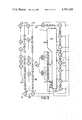
- FIGS. 1a, 1b give two elementary block diagrams of apparatus according to the invention.
- FIG. 2 gives three matrices A, B, C for the updating of the syndrome sequence of the convolutional code.
- FIG. 3 gives a schematic presentation of a number of preferred codes.
- FIG. 4 gives an apparatus for the correction of errors with the aid of a convolutional code and for the signalizing of non-correctable errors.
- FIG. 5 gives the system equation expanded for the feedback decoder in FIG. 4.
- FIG. 6 gives for the case of FIG. 4 the values of an updated syndrome sequence where a correction is carried out.
- FIG. 7 gives for the case of FIG. 4 the values of an updated syndrome sequence by means of which a residue signal can be generated.
- FIG. 8 gives a further implementation of the circuit of FIG. 4.
- FIG. 9 gives yet another implementation of the circuit according to FIG. 4.
- FIG. 10 gives a timing diagram of signals for the case of FIG. 9.
- FIG. 11 gives a further apparatus according to the invention.
- FIG. 13 gives in addition a third apparatus according to the invention.
- FIGS. 14a, 14b give a mode of operation for the execution of a correction in the case of an interleaved organization of the n-tuples of code elements.
- FIG. 1a gives an elementary block diagram of an apparatus according to the invention.
- the n-tuples of code elements appear at input 500.
- Block 502 comprises first syndrome-forming circuit for forming a sequence of syndrome signals.
- Element 504 is an address shift register which comprises modification elements in the form of (symbolically indicated) exclusive-OR elements.
- Element 506 is a read-only memory for forming, from a sequence of syndrome elements, a correction for the sequence of n-tuples. This correction is applied by means of EXCLUSIVE-OR element 508 which if necessary is multiple.
- Element 503 is delay element for delaying the n-tuples of code elements for as long as corresponds to the delay in the generation of the correction elements in read-only memory 506: this can relate to as many bit cells as the length of address register 504.
- the correction quantity for element 508 is also supplied to address shift register 504 in order to update the syndrome sequence by means of the Exclusive-OR elements in register 504 so as to compensate for the modification in the n-tuples of code elements which were received at input 500 and have now arrived at element 508.
- the modified information is supplied to second syndrome-forming means 512 so as to form secondary (n-k)-tuples of syndrome elements from the updated information.
- This so-called residue signal contains information relating to non-correctable errors: if the correction has been correct (and has thus been possible) this residue signal is composed for example entirely of zeros.
- the residue signal is supplied to detector 514 which is arranged so as to detect a non-zero syndrome signal and in this way to indicate an unreliable segment in the corrected sequence of n-tuples.
- This can for example be a counter which is reset to the zero state by a received "1" and counts forward by the clock. A particular state then indicates that the output signal is again reliable: this signalization appears at line 516.
- Element 509 is again a delay element for compensating a possible detection delay in element 512.
- Element 511 is a processing element which for example converts the restored n-tuples of code elements into the k-tuples of information elements again, if the signal on line 516 makes that possible. The user information finally becomes available on line 510.
- FIG. 1b gives a modified block diagram, in particular for a non-systematic convolutional code.
- the code bits appear at input 520.
- Element 526 is a read-only memory. Whenever a following syndrome bit is received in element 526, it gives in the first place two correction elements for the EXCLUSIVE-OR elements 528, 530 respectively.
- the blocks 532, 534 represent delay elements corresponding to element 503 in FIG. 1a.
- the corrected n-tuples of code elements appear at outputs 536, 538. Furthermore whenever a correction takes place (by means of elements 528, 530) a residue signal is delivered at output 540 by the read-only memory 526. This signal has the value 1 if the sequence of syndrome bits present at that instant in address shift register 524 is such that a further correction to the stream of n-tuples of code bits would still be necessary. This correction is then no longer useful, because of the limited error-correction capacity of the code.
- This residue bit is directly correlated with the value of the syndrome bit which (after modification if necessary) has originated from the least recently received syndrome bit in address register 524. The further processing of residue signal and information/code signals has already been discussed for the case of FIG. 1a.
- (j), (j-p), et cetera are running indices and the quantities G(0) . . . G(p) are matrices with a dimension of (nxk) elements each of which can only be 0 or 1. All elementary operations take place modulo 2, while at least the matrices G(0) and G(p) are not identically equal to zero.
- the number p is the encoding constraint length.
- the code is systematic if all the information bits of a k-tuple again form part of an n-tuple of code bits, or can be derived from k code bits of an undisturbed k-tuple of code bits respectively.
- a syndrome sequence is formed which is composed of (n-k)-tuples: s(j), s(j+1), s(j+2), . . . by means of the following operation on the n-tuples y'(j) possibly corrupted by errors. This possible error is indicated here by an accent:
- Hi always represents a matrix with a dimension of (n-k)xn elements, which elements can have only the values 0 and 1.
- the matrices Hi satisfy a defining equation to be discussed later, related to the matrices Gi.
- the formation of the syndrome amounts to the bit-by-bit addition of the sequence of received parity bits and the sequence of reconstructed parity bits. Examples will be given hereinafter. The above description is valid for all convolutional codes. Necessary and sufficient conditions for a technically interesting convolutional code (namely one which can correct the error in a number ⁇ 1 of disturbed n-tuples of code elements) will be discussed hereinafter.
- u is a natural number which is greater than or equal to p and is called the decoding constraint length.
- (i), (i-u), and so on are running indices.
- the quantity t(i) is called the updated syndrome; it is a vector with the dimension u ⁇ (n-k), and for which the elements can only have the values zero and 1.
- the letters A, B and C represent three matrices which are depicted in FIG. 2.
- the matrix A has a dimension of ⁇ u ⁇ (n-k) ⁇ square.
- the matrix B has a dimension of u ⁇ (n-k) by (n-k).
- the matrix C has a dimension of n by u ⁇ (n-k).
- the matrix C therefore comprises all the matrices H1, H2 . . . Hp which have been pointed out above.
- t(i+1) The expression for t(i+1) will next be considered further. If e(i-u) is the first disturbance from a (possible) sequence of disturbances, then t(i) can be partitioned vectorially by means of the following matrix equation, in which each line relates to an element of the vector t(i): ##EQU1## This therefore concerns u syndrome symbols and the height of the matrices is thus u(n-k) elements. In the above the updating of the syndrome quantities has not yet taken place. The disturbance e(i-u) is thus reconstructed as:
- the influence of the matrix A on the updating of the syndrome symbols is that the effects are shifted to the bottom (u-i).(n-k) matrix lines (downshift) and that the top (n-k) lines contain only zeros (truncate).
- the matrix B ensures that the updated syndrome symbols appear at the correct place in the updated syndrome sequence.
- the matrix C comprises the array of the partial effects due to the disturbance.
- Convolutional codes can easily be described by means of the D-transformation. This is based on a sequence of elements Z(m), Z(m+1), Z(m+2) . . . , in which m is a running index. In connection with the above Z is for example a sequence of n-tuples of information bits. This sequence can contain the same terms at different places. With the aid of the delay operator D the transform Z (D) of such a sequence becomes:
- Each element of the matrix G(D), hence g (i, j) (D) is now a polynomial in the delay operator D with coefficients 0 or 1.
- the coding can be described by means of a parity-check matrix, H (D).
- This matrix has a dimension of (n-k) ⁇ n elements h (i, j).
- Each element is again a polynomial in the delay operator D with coefficients 0 or 1.
- This matrix satisfies the equation:
- an element from the sequence of (n-k)-tuples of syndrome elements s (m) . . . s (m+u) is always formed from a segment of the code sequence of n-tuples y (m) . . . y (m+u). This then depends entirely on a corresponding element of a segment from the error sequence: e (m) . . . e (m+u). In the correction the value of e (m) must be determined from the syndrome segment. In a serially operating decoder this is the element of the segment that arrived first.
- the weight of a segment is to be understood as the number of n-tuples of that error segment which are not equal to 0.
- An initial segment of length (u+1) of a code is to be understood as a segment ##EQU6## where y (D) is the transform of a code sequence having y(0) as first n-tuple differing from zero.
- the minimum weight d (u) of a convolutional code be the minimum of the weights of all the possible initial segments of length (u+1) of the code.
- the syndrome segment ##EQU7## which is generated on the basis of an initial segment ##EQU8## is composed entirely of zeros, which follows from the aforementioned equation (2) and from the fact that y (D) represents an undisturbed sequence of n-tuples of code elements.
- e (D) and e' (D) are two error sequences for which e (0) and e' (0) are mutually different and both unequal to zero, while all earlier disturbances had the value zero, then these error sequences give then and only then the same syndrome segment if the truncated (broken-off) sum: ##EQU9## is an initial segment of the convolutional code.
- a convolutional code with decoding constraint length u can then correct a number Q ( ⁇ 1) of disturbed n-tuples wthin a segment of (u+1) seccessive n-tuples if the above-defined minimum weight of that initial segment of the code is at least equal to:
- An (n,k,p) convolutional code is now said to be q-fold error correcting if a finite number u exists such that every disturbance of the sequence of n-tuples of code elements which influences at most q u-tuples in each segment of (u+1) successive n-tuples is still correctable. If the efficiency (k/n) is fixed, then for a fixed value of q the smallest value of u is aimed at.
- the minimum weight d (j) as defined above is now determined by the set of all the initial segments of the code having length (j+1) n-tuples. If two codes possess the same set of initial segments having length (u+1) they therefore have the same weight provided 0 ⁇ j ⁇ u.
- Each branch of the tree structure indicates a generator polynomial, where the terms are indicated in each case.
- the term D 0 is always optional.
- the branch on the furthest left of the tree structure is characterized by a generator polynomial having the following powers of the delay operator D.
- D 0 (optional), D 1 , D 2 , D 5 , D 6 , D 8 , D 10 , D 11 , D 12 , D 13 , D 15 .
- the compact notation of FIG. 3 therefore gives for the correction of three n-tuples per segment, twenty codes; for the correction of two n-tuples per segment, twelve codes; and for the correction of one n-tuple per segment four codes (each branch counts twice because the indication ⁇ D 0 means that the term in D 0 is optional).
- the value of p can therefore be lower than the value of u.
- Other codes having the same correction capacities per segment are possible, but for these the value of u is always greater than the minimum. In relation to the information stream these therefore have a smaller average correction capacity.
- the formation of the residue which is composed of a sequence of (n-k)-tuples, will be described next.
- This has the same form as the syndrome sequence.
- the purpose of the residue information is to indicate, at the encounter with an uncorrectable disturbance, an interval in the sequence of n-tuples of code elements, during which interval this information will be uncorrectable.
- the matrix Ho defined earlier, does not occur as the submatrix of the likewise previously described matrix C.
- the residue signal is determined by the syndrome sequence and hence indirectly by the error sequence.
- the formation of the residue gives a post check on the decoding process, for through the reconstruction of the error sequence there arises directly the possibility of reconstructing again thereby the appertaining syndrome sequence.
- the reconstructed syndrome sequence should coincide with the original constructed syndrome sequence.
- the first is the maximum detection delay. If y" (m) is the first disturbed n-tuple of code elements which forms part of a segment of the code sequence, in which segment an uncorrectable, but indeed detectable error is present, and if this as first non-zero residue signal ((n-k)-tuple) causes the element r (m+w), then w is the detection delay. Within a certain class of disturbances to be detected in this way the value of w possesses a finite maximum.
- the second quantity is the maximum sequence (run length) of residue signals which have the value "0" and therefore each in themselves indicate the undisturbed state, while the n-tuples of code elements do indeed contain an uncorrectable error which does however belong to aforesaid class of errors to be detected.
- Such a sequence of residue signals equal to zero will therefore be preceded by a signal not equal to 0 and followed by a signal unequal to 0.
- a maximum value is to be found for successive residue signals having the value zero.
- Both the maximum detection delay as well as the maximum length of said sequence of residue signals equal to zero are for example to be found by simulation by means of a computer. The consequences for the construction of a decoding machine will be discussed hereinafter.
- FIG. 4 gives a detailed diagram of an apparatus for the correction of a stream of information elements protected by a convolutional code.
- the code is linear and systematic.
- FIG. 5 gives the expanded system equation of the feedback decoder, in which in this case very simple versions of the matrices according to FIG. 2 have been included.
- the function f 1 ⁇ s (i), t (i) ⁇ ensures the updating of the information bits and hence also the updating of the syndrome bits by means of the EXCLUSIVE-OR gates 242-248.
- the function f 2 ⁇ s (i), t (i) ⁇ is used for the updating of the syndrome bits, after successive correction thereof, by means of f 1 ⁇ s (i), t (i) ⁇ , whereby the secondary syndrome bits or residue bits are generated.
- the functions f 1 and f 2 are therefore in principle two different functions. Since the convolutional code is systematic, the last column of the matrix C is composed entirely of element 0, with this matrix not of course containing the matrix H0.
- the logic function to be formed by the read-only memory 250 can be found.
- the unmodified syndrome s (i) therefore appears at the output of EXCLUSIVE-OR element 226 and the successive elements of t (i) in order at the outputs of shift register stages 228 to 241 inclusive.
- the column (0) of FIG. 6 therefore relates to the least recently arrived syndrome signals.
- the elements d1, d2 represent mutually independent arbitrary bit values 0, 1 (don't cares).
- the first line gives the influence on the syndrome of a single disturbed two-tuple for which the information bit has arrived correctly in element 218.
- the quantity d1 here indicates the arbitrary value of the parity bit of that two-tuple.
- the lines 2 to 8a inclusive give the nine possibilities for the combination of two disturbed 2-tuples, where the second disturbed 2-tuple has only an erroneous parity bit.
- the second address bit is therefore inverted with respect to line 1, in line 3 the third, et cetera (the inversion of the first address bit has of course already been included in the first line).
- Line 8a is a special case of line 15.
- Line 15a is a special case of (line 1 or line 15). These lines 8a, 15a are therefore not implemented.
- the quantity d1 appearing repeatedly in the first column means that the information from element 241 is not relevant here for the addressing, and that the connection in question to read-only memory 250 could be omitted in so far as the implementation of FIG. 6 is concerned.
- FIG. 7 gives a number of further addresses for which the function f 2 has the value 1.
- the element d 3 is again an arbitrary (don't care) information value which is independent of d 1 and d 2 .
- Line 16 indicates a single error in a parity bit. This is passed unchanged by each of the elements 242, 244, 246, 248 and is corrected only in element 252.
- Lines 17 to 23a inclusive are generated under the influence of two disturbed 2-tuples having only the parity bit disturbed in each case. These lines are generated by shifting line 16 to the right and adding it to itself.
- Lines 24 to 30a inclusive are generated by a sequential order of a disturbed parity bit and thereafter a two-tuple in which certainly the information bit (and possibly also the parity bit) is disturbed.
- the length of shift register 254/262 is determined by the longest possible sequence of zero signals which can occur for an error sequence which the apparatus must be able to detect.
- the choice of the errors to be detected is a design parameter.
- the shift-register stages 266 to 274 inclusive are connected so as to store the corrected information elements during a number of bit cells, since it is possible that the signal at terminal 266 assumes un unreliability value only after a delay. This delay depends on the disturbance pattern.
- the delay of the information elements must be sufficiently large that it is at least equal to the maximum delay of the unreliability signal at terminal 266 in connection with the class of errors, which, although uncorrectable, have to be detected by the apparatus.
- the numbers of shift-register stages 254/262 and 266/274 can be equal to one another, but this is not necessary. However, these numbers will as a rule be smaller than the numbers of shift-register stages 206/218. If the code is not systematic the function f is composed of n-tuples of correction elements, and the function f of (n-k)-tuples of secondary syndrome elements, where (n-k) is always ⁇ 1. From the aforementioned (n-k)-tuples an OR function is then formed again so as to signalize an unreliability signal. A user's apparatus can be connected at the output 276. In the case of a non-systematic code this also comprises an apparatus for regenerating the k-tuples of information elements.
- the syndrome-forming means 512 in FIG. 4 are included in the logic function generator 506 (here a read-only memory), so that element 514 is connected to a second output of element 506.
- the logic function generator 506 here a read-only memory
- element 514 is connected to a second output of element 506.
- a read-only memory a programmable or otherwise logic arrangement (array) or PLA can be used.
- FIGS. 6, 7 also shows that FIG. 7 can be obtained by performing the following operations:
- FIG. 8 A first system implementation, parallel to FIG. 4, is indicated in FIG. 8.
- the flow of syndrome bits enters and this is (not indicated) updated for the correction of the stream of information bits.
- the read-only memory 306 provides the function f 1 , as shown in FIG. 6. This function is of course used for correcting the information elements and compensating the syndrome sequence for this, but for brevity this is not shown. Furthermore f 1 is supplied to the AND gate 310.
- the word W which has been defined above is generated by means not shown.
- the read-only memory 308 is identical with the read-only memory 306 but is addressed by another address word: Hence in this way is generated:
- Element 322 is a changeover switch energized by the clock.
- Element 326 is a trigger circuit energized by the clock at input 324.
- Element 328 is an OR gate and 322 an AND gate and element 330 is an inverting buffer with small delay with respect to the clock-pulse period.
- FIG. 10 gives an explanatory clock-pulse diagram.
- Line 340 gives the clock-pulse signal, synchronous with the bit stream, from a clock not shown further for brevity.
- the trigger circuit is activated each time by the rising edges of the pulses.
- Line 342 gives the state of switch 322.
- L indicates that the switches in FIG. 11 (see figure) are in the lower state and that the switch 322 in FIG. 9 is in the lower state. Then the aforementioned word W is therefore added to the operative address.
- R of course means the opposite of L: in both figures the switches are in the upper position, and the word W is not added to the operative address.
- Line 344 gives the output signal from the read-only memory 306 for signalizing a disturbed parity bit.
- AND gate 332 is therefore open so as to deliver a secondary syndrome signal as output signal. Since however the entire system is synchronously operating, only the signals operative in the second half of the clock-pulse cycle are shifted through to the following shift-register stage. In this case AND gate 322 is therefore also blocked at the relevant point in time.
- the fig. only shows limited changes with respect to FIG. 4.
- the input shift-register comprises fifteen stages 56 to 84 inclusive.
- the code is indicated in FIG. 3 as fifth from the left. This code therefore has a small encoding constraint length.
- the parity is determined by the five EXCLUSIVE-OR elements 86 to 94 inclusive. This therefore takes place again without the participation of the D 0 in the relevant polynominal. Terminal 22 receives the parity bits and EXCLUSIVE-OR element 96 therefore gives the syndrome sequence.
- the trigger circuit 128, OR gate 130, inverter 132 and AND gate 138 have been discussed in the case of FIG. 9.
- the two NOR gates 160, 162 with the NAND gate 164 correspond to the OR gate 264 in FIG. 4. In this way the unreliability signal appears at terminal 166 together with the delayed information after the correction thereof (at terminal 188).
- the two shift registers at the output have the length of ten stages. These lengths do not in principle need to be the same. They are both shorter than the decoding constraint length.
- the information arrives at terminals 360, 362.
- the basic elements of the circuit are shown in the conventional manner.
- the generator polynominals contain the following terms in the delay polynominals contain the following terms in the delay operator D: D 1 (branch 364), D 5 (branch 366), D 6 (branch 368), D 9 (branch 370), D 14 (branch 372).
- the generator polynominal contains the terms in D: D 2 (branch 374), D 4 (branch 376), D 5 (branch 378), D 6 (branch 380), D 7 (branch 382), D 11 (branch 384).
- FIG. 13 gives a feedback decoder for the code generated with the circuit of FIG. 12.
- the circuit is for the greater part of similar construction to the one in FIG. 11.
- the information bits arrive at the terminals 386, 388 which are connected to the corresponding output terminals in FIG. 12.
- the parity bits appear at the terminal 390 which corresponds to terminal 390 in FIG. 12.
- the information bits are supplied to 14-bit shift registers 394, 395. From these the parity bits are reconstructed and from these again the syndrome bits on line 392.
- the latter are supplied to an address register of 13 bits (+1 post-connected shift-register stage) 394, in which EXCLUSIVE-OR elements are again included as updating devices.
- the read-only memory 396 is similarly organized to the read-only memory 250 in FIG.
- the first output 398 leads to EXCLUSIVE-OR element 400 so as to update the first information stream.
- the second output 402 leads to EXCLUSIVE-OR element 404 so as to update the second information stream.
- Both outputs 398, 402 lead to the address register 394 so as to compensate the syndrome sequence for the changes in the information streams.
- element 406 for example operates upon three input signals (one syndrome signal and two correction bits) and thus works as a molulo-2 adder for three bits.
- the third output 408 of read-only memory 396 leads to AND gate 410 so as to generate the residue signal. This is stored in a 9-bit shift register 412. The unreliability signal then appears via NOR and NAND gates at terminal 414.
- shift registers can be connected (see elements 168-186 in FIG. 11, or 266-274 in FIG. 4) so as to delay the information by a time that at the maximum corresponds to the detection delay of the unreliability signal at terminal 414.
- the latter shift registers are not drawn here.
- the aforementioned unreliability signal activates an in itself known digital linear interpolator which performs an interpolation of adjacent signal values (from the same channel) over a value range of 9 bits.
- the corrected codes, or the interpolation values respectively, are again supplied to a D/A converter and acoustic reproduction apparatuses.
- the basic elements of the acoustic channels are completely known and will not be discussed here further.
- FIG. 14a gives a first interpolation method. There are three classes of signals 0, 1 and 2 in the interleaving organization. There are further two acoustically separate signals, left (L) and right (R). The third line gives the unreliability signal which indicates that the class "0" is disturbed.
- the interpolation now takes place between the adjacent signals having the same acoustic origin, as indicated at the fourth line, the interpolation is therefore according to:
- the signals of the class "1" are correctly L (m).
- the signals "R” are recovered in a corresponding manner. Interpolation with for example quadratic formulae is also possible hereafter, and likewise the subdivision of the signals into more classes.
Landscapes
- Engineering & Computer Science (AREA)
- Computer Networks & Wireless Communication (AREA)
- Signal Processing (AREA)
- Physics & Mathematics (AREA)
- Probability & Statistics with Applications (AREA)
- Theoretical Computer Science (AREA)
- Error Detection And Correction (AREA)
- Detection And Correction Of Errors (AREA)
Applications Claiming Priority (2)
| Application Number | Priority Date | Filing Date | Title |
|---|---|---|---|
| NL7907141 | 1979-09-26 | ||
| NL7907141A NL7907141A (nl) | 1979-09-26 | 1979-09-26 | Inrichting voor het behandelen van een informatiestroom met behulp van een foutenkorrigerende konvolutiekode en inrichting voor het detekteren van een daarbij alsnog onherstelbare fout. |
Publications (1)
| Publication Number | Publication Date |
|---|---|
| US4354269A true US4354269A (en) | 1982-10-12 |
Family
ID=19833913
Family Applications (1)
| Application Number | Title | Priority Date | Filing Date |
|---|---|---|---|
| US06/185,050 Expired - Lifetime US4354269A (en) | 1979-09-26 | 1980-09-08 | Apparatus for the processing of an information stream with the aid of an error-correcting convolutional code and apparatus for the detection of an error still irremediable in this processing |
Country Status (7)
| Country | Link |
|---|---|
| US (1) | US4354269A (de) |
| EP (1) | EP0026516B1 (de) |
| JP (1) | JPS5657150A (de) |
| AT (1) | ATE10550T1 (de) |
| AU (1) | AU6262180A (de) |
| DE (1) | DE3069713D1 (de) |
| NL (1) | NL7907141A (de) |
Cited By (28)
| Publication number | Priority date | Publication date | Assignee | Title |
|---|---|---|---|---|
| US4473902A (en) * | 1982-04-22 | 1984-09-25 | Sperrt Corporation | Error correcting code processing system |
| US4559625A (en) * | 1983-07-28 | 1985-12-17 | Cyclotomics, Inc. | Interleavers for digital communications |
| US4630032A (en) * | 1983-06-03 | 1986-12-16 | British Telecommunications | Apparatus for decoding error-correcting codes |
| US4637021A (en) * | 1983-09-28 | 1987-01-13 | Pioneer Electronic Corporation | Multiple pass error correction |
| US4669084A (en) * | 1985-05-23 | 1987-05-26 | Harris Corporation | Error correction processing scheme for sequential codec |
| FR2616986A1 (fr) * | 1987-06-17 | 1988-12-23 | Matra | Dispositif de decodage par syndromes de messages en code convolutionnel |
| EP0264784A3 (en) * | 1986-10-14 | 1990-06-06 | Nec Corporation | Convolutional encoder |
| US5491705A (en) * | 1992-06-18 | 1996-02-13 | The United States Of America As Represented By The Secretary Of The Air Force | De bruijn graph based VLSI viterbi decoder |
| US5596554A (en) * | 1993-06-04 | 1997-01-21 | Hagadorn; Hubert W. | Set operation in a timepiece having an electrooptical display |
| GB2328594A (en) * | 1997-06-18 | 1999-02-24 | Motorola Inc | Soft-decision syndrome-based decoder for convolutional codes |
| GB2328846A (en) * | 1997-06-18 | 1999-03-03 | Motorola Inc | Syndrome-based channel quality or message structure determiner |
| US6029160A (en) * | 1995-05-24 | 2000-02-22 | International Business Machines Corporation | Method and means for linking a database system with a system for filing data |
| WO2000041347A1 (en) * | 1999-01-04 | 2000-07-13 | Motorola Inc. | Method and apparatus for interleaving in a communication system |
| WO2002021700A1 (en) * | 2000-09-06 | 2002-03-14 | Motorola Inc. | Syndrome assisted iterative decoder for turbo codes |
| US6360349B1 (en) * | 1997-05-26 | 2002-03-19 | Nippon Precision Circuits, Inc. | Syndrome computing apparatus |
| US6453325B1 (en) | 1995-05-24 | 2002-09-17 | International Business Machines Corporation | Method and means for backup and restoration of a database system linked to a system for filing data |
| US6469514B2 (en) * | 2000-04-04 | 2002-10-22 | Advantest Corporation | Timing calibration apparatus and method in a semiconductor integrated circuit tester |
| US20030028839A1 (en) * | 2001-03-30 | 2003-02-06 | Coene Willem Marie Julia Marcel | Methods and devices for converting as well as decoding a stream of data bits, signal and record carrier |
| US20030099299A1 (en) * | 2001-09-26 | 2003-05-29 | Rogerson Gerald D. | Method and apparatus for data transfer using a time division multiple frequency scheme |
| US20030202537A1 (en) * | 2001-09-26 | 2003-10-30 | General Atomics | Method and apparatus for data transfer using a time division multiple frequency scheme supplemented with polarity modulation |
| US20040008729A1 (en) * | 2001-09-26 | 2004-01-15 | General Atomics | Method and apparatus for data transfer using a time division multiple frequency scheme with additional modulation |
| US20040028011A1 (en) * | 2001-09-26 | 2004-02-12 | General Atomics | Method and apparatus for adapting signaling to maximize the efficiency of spectrum usage for multi-band systems in the presence of interference |
| US20040028012A1 (en) * | 2001-09-26 | 2004-02-12 | General Atomics | Flexible method and apparatus for encoding and decoding signals using a time division multiple frequency scheme |
| US20040048574A1 (en) * | 2001-09-26 | 2004-03-11 | General Atomics | Method and apparatus for adapting multi-band ultra-wideband signaling to interference sources |
| US20040240263A1 (en) * | 2002-01-25 | 2004-12-02 | Rarick Leonard D. | System and method for small read only data |
| US20070011598A1 (en) * | 2005-06-15 | 2007-01-11 | Hitachi Global Storage Technologies Netherlands B.V. | Error detection and correction for encoded data |
| US20140136926A1 (en) * | 2005-04-28 | 2014-05-15 | Micron Technology, Inc. | Non-systematic coded error correction |
| US10116430B1 (en) * | 2016-09-01 | 2018-10-30 | Xilinx, Inc. | Alignment marker independent data alignment for a receiver |
Families Citing this family (3)
| Publication number | Priority date | Publication date | Assignee | Title |
|---|---|---|---|---|
| BE890280A (fr) * | 1981-09-09 | 1982-03-09 | Belge Lampes Mat Electr Mble | Dispositif de codage et de decodage base sur un code de convolution |
| DE4218529A1 (de) * | 1992-06-05 | 1993-12-09 | Philips Patentverwaltung | Decoder mit Bitfehlerratenschätzung und/oder Wortsynchronisation |
| GB2302633B (en) * | 1995-06-24 | 2000-02-16 | Motorola Ltd | Convolutional coder |
Citations (6)
| Publication number | Priority date | Publication date | Assignee | Title |
|---|---|---|---|---|
| US3402393A (en) * | 1962-07-25 | 1968-09-17 | Codex Corp | Error detection and correction in signal transmission by use of convolution codes |
| US3508197A (en) * | 1966-12-23 | 1970-04-21 | Bell Telephone Labor Inc | Single character error and burst-error correcting systems utilizing convolution codes |
| US3588819A (en) * | 1968-09-18 | 1971-06-28 | Bell Telephone Labor Inc | Double-character erasure correcting system |
| US3593282A (en) * | 1969-11-04 | 1971-07-13 | Bell Telephone Labor Inc | Character-error and burst-error correcting systems utilizing self-orthogonal convolution codes |
| US3697947A (en) * | 1970-10-31 | 1972-10-10 | American Data Systems Inc | Character correcting coding system and method for deriving the same |
| US4291406A (en) * | 1979-08-06 | 1981-09-22 | International Business Machines Corporation | Error correction on burst channels by sequential decoding |
-
1979
- 1979-09-26 NL NL7907141A patent/NL7907141A/nl not_active Application Discontinuation
-
1980
- 1980-09-08 US US06/185,050 patent/US4354269A/en not_active Expired - Lifetime
- 1980-09-11 DE DE8080200848T patent/DE3069713D1/de not_active Expired
- 1980-09-11 EP EP80200848A patent/EP0026516B1/de not_active Expired
- 1980-09-11 AT AT80200848T patent/ATE10550T1/de not_active IP Right Cessation
- 1980-09-23 AU AU62621/80A patent/AU6262180A/en not_active Abandoned
- 1980-09-26 JP JP13311480A patent/JPS5657150A/ja active Granted
Patent Citations (6)
| Publication number | Priority date | Publication date | Assignee | Title |
|---|---|---|---|---|
| US3402393A (en) * | 1962-07-25 | 1968-09-17 | Codex Corp | Error detection and correction in signal transmission by use of convolution codes |
| US3508197A (en) * | 1966-12-23 | 1970-04-21 | Bell Telephone Labor Inc | Single character error and burst-error correcting systems utilizing convolution codes |
| US3588819A (en) * | 1968-09-18 | 1971-06-28 | Bell Telephone Labor Inc | Double-character erasure correcting system |
| US3593282A (en) * | 1969-11-04 | 1971-07-13 | Bell Telephone Labor Inc | Character-error and burst-error correcting systems utilizing self-orthogonal convolution codes |
| US3697947A (en) * | 1970-10-31 | 1972-10-10 | American Data Systems Inc | Character correcting coding system and method for deriving the same |
| US4291406A (en) * | 1979-08-06 | 1981-09-22 | International Business Machines Corporation | Error correction on burst channels by sequential decoding |
Cited By (45)
| Publication number | Priority date | Publication date | Assignee | Title |
|---|---|---|---|---|
| US4473902A (en) * | 1982-04-22 | 1984-09-25 | Sperrt Corporation | Error correcting code processing system |
| US4630032A (en) * | 1983-06-03 | 1986-12-16 | British Telecommunications | Apparatus for decoding error-correcting codes |
| US4559625A (en) * | 1983-07-28 | 1985-12-17 | Cyclotomics, Inc. | Interleavers for digital communications |
| US4637021A (en) * | 1983-09-28 | 1987-01-13 | Pioneer Electronic Corporation | Multiple pass error correction |
| US4669084A (en) * | 1985-05-23 | 1987-05-26 | Harris Corporation | Error correction processing scheme for sequential codec |
| EP0264784A3 (en) * | 1986-10-14 | 1990-06-06 | Nec Corporation | Convolutional encoder |
| FR2616986A1 (fr) * | 1987-06-17 | 1988-12-23 | Matra | Dispositif de decodage par syndromes de messages en code convolutionnel |
| US5491705A (en) * | 1992-06-18 | 1996-02-13 | The United States Of America As Represented By The Secretary Of The Air Force | De bruijn graph based VLSI viterbi decoder |
| US5596554A (en) * | 1993-06-04 | 1997-01-21 | Hagadorn; Hubert W. | Set operation in a timepiece having an electrooptical display |
| US6029160A (en) * | 1995-05-24 | 2000-02-22 | International Business Machines Corporation | Method and means for linking a database system with a system for filing data |
| US6453325B1 (en) | 1995-05-24 | 2002-09-17 | International Business Machines Corporation | Method and means for backup and restoration of a database system linked to a system for filing data |
| US6360349B1 (en) * | 1997-05-26 | 2002-03-19 | Nippon Precision Circuits, Inc. | Syndrome computing apparatus |
| GB2328846A (en) * | 1997-06-18 | 1999-03-03 | Motorola Inc | Syndrome-based channel quality or message structure determiner |
| US6009552A (en) * | 1997-06-18 | 1999-12-28 | Motorola, Inc. | Soft-decision syndrome-based decoder for convolutional codes |
| US5936972A (en) * | 1997-06-18 | 1999-08-10 | Motorola, Inc. | Syndrome-based channel quality or message structure determiner |
| GB2328846B (en) * | 1997-06-18 | 2002-07-03 | Motorola Inc | Syndrome-based channel quality or message structure determiner |
| GB2328594B (en) * | 1997-06-18 | 2002-11-06 | Motorola Inc | Soft-decision syndrome-based decoder for convolutional codes |
| GB2328594A (en) * | 1997-06-18 | 1999-02-24 | Motorola Inc | Soft-decision syndrome-based decoder for convolutional codes |
| WO2000041347A1 (en) * | 1999-01-04 | 2000-07-13 | Motorola Inc. | Method and apparatus for interleaving in a communication system |
| US6469514B2 (en) * | 2000-04-04 | 2002-10-22 | Advantest Corporation | Timing calibration apparatus and method in a semiconductor integrated circuit tester |
| WO2002021700A1 (en) * | 2000-09-06 | 2002-03-14 | Motorola Inc. | Syndrome assisted iterative decoder for turbo codes |
| US6671852B1 (en) | 2000-09-06 | 2003-12-30 | Motorola, Inc. | Syndrome assisted iterative decoder for turbo codes |
| US20030028839A1 (en) * | 2001-03-30 | 2003-02-06 | Coene Willem Marie Julia Marcel | Methods and devices for converting as well as decoding a stream of data bits, signal and record carrier |
| US20030099299A1 (en) * | 2001-09-26 | 2003-05-29 | Rogerson Gerald D. | Method and apparatus for data transfer using a time division multiple frequency scheme |
| US7609608B2 (en) | 2001-09-26 | 2009-10-27 | General Atomics | Method and apparatus for data transfer using a time division multiple frequency scheme with additional modulation |
| US20040008729A1 (en) * | 2001-09-26 | 2004-01-15 | General Atomics | Method and apparatus for data transfer using a time division multiple frequency scheme with additional modulation |
| US20040028011A1 (en) * | 2001-09-26 | 2004-02-12 | General Atomics | Method and apparatus for adapting signaling to maximize the efficiency of spectrum usage for multi-band systems in the presence of interference |
| US20040028012A1 (en) * | 2001-09-26 | 2004-02-12 | General Atomics | Flexible method and apparatus for encoding and decoding signals using a time division multiple frequency scheme |
| US20040048574A1 (en) * | 2001-09-26 | 2004-03-11 | General Atomics | Method and apparatus for adapting multi-band ultra-wideband signaling to interference sources |
| US8149879B2 (en) | 2001-09-26 | 2012-04-03 | General Atomics | Method and apparatus for data transfer using a time division multiple frequency scheme supplemented with polarity modulation |
| US20030202537A1 (en) * | 2001-09-26 | 2003-10-30 | General Atomics | Method and apparatus for data transfer using a time division multiple frequency scheme supplemented with polarity modulation |
| US6895059B2 (en) | 2001-09-26 | 2005-05-17 | General Atomics | Method and apparatus for data transfer using a time division multiple frequency scheme |
| US20050232371A1 (en) * | 2001-09-26 | 2005-10-20 | General Atomics | Method and apparatus for data transfer using wideband bursts |
| US7436899B2 (en) | 2001-09-26 | 2008-10-14 | General Atomics | Method and apparatus for data transfer using wideband bursts |
| US7236464B2 (en) | 2001-09-26 | 2007-06-26 | General Atomics | Flexible method and apparatus for encoding and decoding signals using a time division multiple frequency scheme |
| US7321601B2 (en) | 2001-09-26 | 2008-01-22 | General Atomics | Method and apparatus for data transfer using a time division multiple frequency scheme supplemented with polarity modulation |
| US7342973B2 (en) | 2001-09-26 | 2008-03-11 | General Atomics | Method and apparatus for adapting multi-band ultra-wideband signaling to interference sources |
| US7403575B2 (en) | 2001-09-26 | 2008-07-22 | General Atomics | Method and apparatus for adapting signaling to maximize the efficiency of spectrum usage for multi-band systems in the presence of interference |
| US6870775B2 (en) * | 2002-01-25 | 2005-03-22 | Sun Microsystems, Inc. | System and method for small read only data |
| US20040240263A1 (en) * | 2002-01-25 | 2004-12-02 | Rarick Leonard D. | System and method for small read only data |
| US20140136926A1 (en) * | 2005-04-28 | 2014-05-15 | Micron Technology, Inc. | Non-systematic coded error correction |
| US9229802B2 (en) * | 2005-04-28 | 2016-01-05 | Micron Technology, Inc. | Non-systematic coded error correction |
| US20070011598A1 (en) * | 2005-06-15 | 2007-01-11 | Hitachi Global Storage Technologies Netherlands B.V. | Error detection and correction for encoded data |
| US7653862B2 (en) * | 2005-06-15 | 2010-01-26 | Hitachi Global Storage Technologies Netherlands B.V. | Error detection and correction for encoded data |
| US10116430B1 (en) * | 2016-09-01 | 2018-10-30 | Xilinx, Inc. | Alignment marker independent data alignment for a receiver |
Also Published As
| Publication number | Publication date |
|---|---|
| NL7907141A (nl) | 1981-03-30 |
| DE3069713D1 (en) | 1985-01-10 |
| JPS5657150A (en) | 1981-05-19 |
| ATE10550T1 (de) | 1984-12-15 |
| EP0026516A1 (de) | 1981-04-08 |
| EP0026516B1 (de) | 1984-11-28 |
| JPS6252903B2 (de) | 1987-11-07 |
| AU6262180A (en) | 1981-04-09 |
Similar Documents
| Publication | Publication Date | Title |
|---|---|---|
| EP0026516A1 (de) | Apparat zur Behandlung eines Datenstroms mit Hilfe eines fehlerkorrigierenden, stetigen Codes und zur Feststellung eines nicht wiedergutzumachenden Fehlers bei dieser Behandlung | |
| US5537429A (en) | Error-correcting method and decoder using the same | |
| US5465260A (en) | Dual purpose cyclic redundancy check | |
| US4928280A (en) | Fast processor for multi-bit error correction codes | |
| US4849974A (en) | PASM and TASM forward error correction and detection code method and apparatus | |
| US4849976A (en) | PASM and TASM forward error correction and detection code method and apparatus | |
| CA1199410A (en) | On-the-fly multibyte error correcting system | |
| US4486882A (en) | System for transmitting binary data via a plurality of channels by means of a convolutional code | |
| US4512020A (en) | Data processing device for processing multiple-symbol data-words based on a symbol-correcting code and having multiple operating modes | |
| US5856987A (en) | Encoder and decoder for an SEC-DED-S4ED rotational code | |
| US4856003A (en) | Error correction code encoder | |
| US5537427A (en) | Modular multiple error correcting code system | |
| US5657331A (en) | Method and apparatus for the generation of simple burst error correcting cyclic codes for use in burst error trapping decoders | |
| US5539755A (en) | Method and apparatus for decoding an error protected block of extended data | |
| CA1213673A (en) | Burst error correction using cyclic block codes | |
| US4055832A (en) | One-error correction convolutional coding system | |
| US5268908A (en) | Low data delay triple coverage code apparatus for on-the-fly error correction | |
| KR200141094Y1 (ko) | 비씨에이취 코드워드를 부호화하는 장치 | |
| US6405339B1 (en) | Parallelized programmable encoder/syndrome generator | |
| US3504340A (en) | Triple error correction circuit | |
| US5450420A (en) | Error correction system for correcting errors generated in digital signals | |
| US7447972B2 (en) | Methods and apparatus for constructing low-density parity check (LDPC) matrix | |
| RU107606U1 (ru) | Устройство хранения и передачи данных с исправлением одиночных ошибок в байте информации и обнаружением произвольных ошибок в байтах информации | |
| RU106771U1 (ru) | Устройство хранения и передачи данных с исправлением ошибок в байте информации и обнаружением ошибок в байтах информации | |
| US5488637A (en) | Decoding method and apparatus having optimum decoding paths |
Legal Events
| Date | Code | Title | Description |
|---|---|---|---|
| AS | Assignment |
Owner name: U.S. PHILIPS CORPORATION; 100 EAST 42ND ST., NEW Y Free format text: ASSIGNMENT OF ASSIGNORS INTEREST.;ASSIGNORS:VRIES, LODEWIJK B.;DIEPEVEEN, MATTHIJS A.;REEL/FRAME:003998/0904 Effective date: 19800902 Owner name: U.S. PHILIPS CORPORATION; A CORP. OF DE.,NEW YORK Free format text: ASSIGNMENT OF ASSIGNORS INTEREST;ASSIGNORS:VRIES, LODEWIJK B.;DIEPEVEEN, MATTHIJS A.;REEL/FRAME:003998/0904 Effective date: 19800902 |
|
| STCF | Information on status: patent grant |
Free format text: PATENTED CASE |