US4355853A - Electrical junction box - Google Patents
Electrical junction box Download PDFInfo
- Publication number
- US4355853A US4355853A US06/111,739 US11173980A US4355853A US 4355853 A US4355853 A US 4355853A US 11173980 A US11173980 A US 11173980A US 4355853 A US4355853 A US 4355853A
- Authority
- US
- United States
- Prior art keywords
- junction box
- main
- circuit board
- auxiliary
- terminal
- Prior art date
- Legal status (The legal status is an assumption and is not a legal conclusion. Google has not performed a legal analysis and makes no representation as to the accuracy of the status listed.)
- Expired - Lifetime
Links
Images



Classifications
-
- H—ELECTRICITY
- H05—ELECTRIC TECHNIQUES NOT OTHERWISE PROVIDED FOR
- H05K—PRINTED CIRCUITS; CASINGS OR CONSTRUCTIONAL DETAILS OF ELECTRIC APPARATUS; MANUFACTURE OF ASSEMBLAGES OF ELECTRICAL COMPONENTS
- H05K7/00—Constructional details common to different types of electric apparatus
- H05K7/02—Arrangements of circuit components or wiring on supporting structure
- H05K7/026—Multiple connections subassemblies
-
- H—ELECTRICITY
- H01—ELECTRIC ELEMENTS
- H01H—ELECTRIC SWITCHES; RELAYS; SELECTORS; EMERGENCY PROTECTIVE DEVICES
- H01H85/00—Protective devices in which the current flows through a part of fusible material and this current is interrupted by displacement of the fusible material when this current becomes excessive
- H01H85/02—Details
- H01H85/20—Bases for supporting the fuse; Separate parts thereof
-
- H—ELECTRICITY
- H01—ELECTRIC ELEMENTS
- H01R—ELECTRICALLY-CONDUCTIVE CONNECTIONS; STRUCTURAL ASSOCIATIONS OF A PLURALITY OF MUTUALLY-INSULATED ELECTRICAL CONNECTING ELEMENTS; COUPLING DEVICES; CURRENT COLLECTORS
- H01R13/00—Details of coupling devices of the kinds covered by groups H01R12/70 or H01R24/00 - H01R33/00
- H01R13/46—Bases; Cases
- H01R13/514—Bases; Cases composed as a modular blocks or assembly, i.e. composed of co-operating parts provided with contact members or holding contact members between them
-
- H—ELECTRICITY
- H02—GENERATION; CONVERSION OR DISTRIBUTION OF ELECTRIC POWER
- H02G—INSTALLATION OF ELECTRIC CABLES OR LINES, OR OF COMBINED OPTICAL AND ELECTRIC CABLES OR LINES
- H02G3/00—Installations of electric cables or lines or protective tubing therefor in or on buildings, equivalent structures or vehicles
- H02G3/02—Details
- H02G3/08—Distribution boxes; Connection or junction boxes
- H02G3/086—Assembled boxes
-
- H—ELECTRICITY
- H01—ELECTRIC ELEMENTS
- H01H—ELECTRIC SWITCHES; RELAYS; SELECTORS; EMERGENCY PROTECTIVE DEVICES
- H01H85/00—Protective devices in which the current flows through a part of fusible material and this current is interrupted by displacement of the fusible material when this current becomes excessive
- H01H85/02—Details
- H01H85/20—Bases for supporting the fuse; Separate parts thereof
- H01H2085/2075—Junction box, having holders integrated with several other holders in a particular wiring layout
- H01H2085/208—Junction box, having holders integrated with several other holders in a particular wiring layout specially adapted for vehicles
-
- H—ELECTRICITY
- H01—ELECTRIC ELEMENTS
- H01H—ELECTRIC SWITCHES; RELAYS; SELECTORS; EMERGENCY PROTECTIVE DEVICES
- H01H85/00—Protective devices in which the current flows through a part of fusible material and this current is interrupted by displacement of the fusible material when this current becomes excessive
- H01H85/02—Details
- H01H85/26—Magazine arrangements
- H01H85/263—Magazine arrangements with spare printed circuit fuse
Definitions
- the invention relates to junction boxes and particularly but not solely to junction boxes for use in motor vehicles.
- junction boxes which comprise an insulating housing enclosing at least one circuit board providing distribution networks for the electrical supplies to basic automobile appliances (e.g. lights, windscreen wipers) instead of the conventional central wire harnesses which consisted of networks of individual wires.
- the junction box affords a substantial saving in space when compared with the conventional wire harness and can conveniently be located in the engine compartment instead of behind the instrument panel.
- the use of diagnostic equipment is also facilitated.
- junction box assembly which can accommodate distribution networks for both the main appliances (e.g. lights, windscreen wipers, etc.) and auxiliary appliances (e.g. air conditioner, headlight wipers) for some vehicles such as export or luxury models without incurring the expense of making such provision where not required.
- main appliances e.g. lights, windscreen wipers, etc.
- auxiliary appliances e.g. air conditioner, headlight wipers
- a main junction box comprises an insulating housing enclosing at least one circuit board providing distribution networks for electrical supplies to main appliances and having plugs or sockets for connection to sockets or plugs terminating main appliance leads, the main junction box having means releasably to couple the main junction box mechanically and electrically to one or more auxiliary junction boxes of similar construction which provide distribution networks for electrical supplies to auxiliary appliances.
- the circuit boards may be printed circuit boards or comprise metal strips mounted on an insulating carrier.
- the housing has means projecting from a rear face to attach the main junction box to the bulkhead of an automobile engine compartment and the coupling means are adapted to operate to permit coupling and uncoupling of the or each auxiliary box with the main box attached to the bulkhead and the circuit board(s) of the or each auxiliary junction box and the circuit board of the main junction box in parallel planes and in coplanar relation, respectively.
- Coupling may be achieved by movement of the or each auxiliary junction box in directions perpendicular to or parallel with the plane of the circuit board of the main junction box.
- the housings of the respective coupling junction boxes may be adapted to dovetail together.
- a junction box assembly for an automobile comprises a main junction box releasably coupled mechanically and electrically to an auxiliary junction box, the main junction box comprising an insulating housing enclosing at least one circuit board providing distribution networks for electrical supplies to main appliances and having plugs or sockets for connection to sockets or plugs terminating main appliance leads, and the auxiliary junction box comprising an insulating housing enclosing at least one circuit board providing distribution networks for electrical supplies to auxiliary appliances, the housing of the main junction box having means projecting from a rear face to attach the main junction box to the bulkhead of an automobile engine compartment.
- a fuse holder adapted to receive either a p.c.b. or cartridge type fuse may be provided in strip form enabling an appropriate number of fuse holders to be severed from the strip and applied as a group to the junction box assembly.
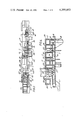
- FIG. 1 is a plan view of the main junction box with auxiliary junction boxes aligned for coupling therewith;
- FIG. 2 is an underplan view
- FIG. 3 is a side elevation partly in cross-section
- FIG. 4 is a cross-sectional view of the main junction box taken along line A--A of FIG. 3;
- FIG. 5 is a plan view of the junction box assembly also showing the location of external connectors.
- FIG. 6 shows various views of a fuse holder in strip and loose-piece form adapted to receive either a printed circuit board fuse or a cartridge fuse.
- the junction box assembly comprises a main box 11 and auxiliary boxes 12 and 13 releasably coupled mechanically and electrically to the main box.
- the main box 11 has main panel members 2, 3 which are oppositely directed as shown in FIGS. 1-3.
- Sidewalls 4, 5 and endwalls 6, 7 extend between the main panel members.
- the sidewalls and endwalls are comprised of wall portions of housing sections 14, 15 described below.
- the main box 11 includes upper and lower housings 14,15 respectively, each molded in one piece from suitable plastics material and fixed together by an ultrasonic welding technique for which plastics studs 16 are provided on the upper housing.
- a bolt-receiving mounting flange 17 extends from one side of the lower housing and cylindrical feet 18 from each end of the other side, the feet being for receipt in mounting channels defined on the engine compartment bulkhead.
- Connector mounting hooks 19 extend at intervals from opposite sides of the lower housing at each end of sockets 25 for external connector 26.
- the upper housing 14 is molded with a series of terminal receiving cavities 20,21,22 open to the top and at opposite sides of each end with coupling sockets 24 open to the respective ends.
- a printed circuit board 27 is sandwiched between upper and lower housings and groups of tab receptacles 28,29,30 are soldered to the p.c.b. and located in the cavities 20,21,22 respectively.
- Other terminals such as a fork receptacle 31 for a p.c.b. may be soldered to the p.c.b. 27.
- a stamped and formed metal bus 36 extends along the housing and is formed at opposite ends into fork contacts 37 which are located in shrouds 41 and protrude from opposite ends of the main box.
- a U-shaped spring (not shown) may extend through slots 42 for connection to the bus to provide a high current tap to an external heavy current carrier.
- commoning tabs 39 extend through apertures in the lower housing.
- the auxiliary boxes 12,13 are of similar, though not identical, construction each having upper and lower housings 50,51 molded in one piece from plastics material and fixed together by an ultrasonic welding technique.
- Latch arms 52 are integrally molded with the upper housings 50 and extend from opposite sides of ends to be coupled with the main box.
- the latch arms are integrally formed with detents 53.
- a printed circuit board 58 (hereinafter referred to as a p.c.b.) is sandwiched between the upper and lower housings and carries various terminals (not shown).
- a coupling end of each housing has a protruding shroud 54 for a stamped and formed coupling terminal 55 which comprises two forks 56,57 opening to opposite directions, one fork 56 connecting to the auxiliary p.c.b. 58 and the other 57 connecting to the p.c.b. 27.
- the boxes are aligned end to end as shown in FIGS. 1 and 2 and pushed together causing the detents on the latch arms to snap into locking apertures 23 in the walls of sockets 24.
- the forks 57 of the auxiliary box connect to the p.c.b. 27 of the main box and the forks 37 of the bus strip of the main box connect to the p.c.b. 27.
- shrouds 54 of each auxiliary box and complementary apertures 59 of the main box are of different sizes to prevent mismatching of the auxiliary boxes with the main box.
- the groups of terminals may be associated with the functions indicated in the drawing and a particular fuse holder adapted for use with the junction box is shown in FIG. 6.
- the fuse holder is molded in one piece from plastics material with a fuse receiving through cavity 60 of reduced width at each end 63.
- Detents 64 protrude into each end of the cavity remote from a top and detent shoulders 66, protrude into the cavity intermediate the ends opposite a shoulder 67.
- the detents 64 and 66 have cam surfaces facing the bottom and top of the cavity, respectively, so that a p.c.b. fuse 62 can be pushed into the cavity from below with the detents snapping into the slots 65 on the p.c.b. and a small cartridge fuse 63 can be pushed into the cavity from above with the detent shoulder 66 snapping over the fuse 63 to lock it against shoulder 67.
- the fuse holder can conveniently be manufactured in strip form, the housings being connected by web 68, which may readily be severed to permit a group of fuse holders with their fuses to be connected to the boxes.
- p.c.b. fuses may be double ended, rotation of the p.c.b. fuse being necessary to provide another live fuse after one has blown.
- the junction box is particularly suitable for use with external connectors described in our U.S. Pat. No. 4,053,197.
Landscapes
- Engineering & Computer Science (AREA)
- Architecture (AREA)
- Civil Engineering (AREA)
- Structural Engineering (AREA)
- Microelectronics & Electronic Packaging (AREA)
- Connection Or Junction Boxes (AREA)
- Coupling Device And Connection With Printed Circuit (AREA)
- Casings For Electric Apparatus (AREA)
Applications Claiming Priority (2)
| Application Number | Priority Date | Filing Date | Title |
|---|---|---|---|
| GB21534/77 | 1977-05-21 | ||
| GB21534/77A GB1601461A (en) | 1977-05-21 | 1977-05-21 | Electrical junction box |
Related Parent Applications (1)
| Application Number | Title | Priority Date | Filing Date |
|---|---|---|---|
| US05906535 Continuation | 1978-05-17 |
Publications (1)
| Publication Number | Publication Date |
|---|---|
| US4355853A true US4355853A (en) | 1982-10-26 |
Family
ID=10164521
Family Applications (1)
| Application Number | Title | Priority Date | Filing Date |
|---|---|---|---|
| US06/111,739 Expired - Lifetime US4355853A (en) | 1977-05-21 | 1980-01-14 | Electrical junction box |
Country Status (12)
| Country | Link |
|---|---|
| US (1) | US4355853A (it) |
| JP (1) | JPS6056319B2 (it) |
| BE (1) | BE867132A (it) |
| BR (1) | BR7803201A (it) |
| CA (1) | CA1102911A (it) |
| DE (1) | DE2821992A1 (it) |
| ES (1) | ES470022A1 (it) |
| FR (1) | FR2399751A1 (it) |
| GB (1) | GB1601461A (it) |
| IT (1) | IT1096082B (it) |
| MX (1) | MX144985A (it) |
| SE (1) | SE440584B (it) |
Cited By (48)
| Publication number | Priority date | Publication date | Assignee | Title |
|---|---|---|---|---|
| US4392701A (en) * | 1980-07-16 | 1983-07-12 | Amp Incorporated | Tap connector assembly |
| US4717348A (en) * | 1985-09-20 | 1988-01-05 | Raymond Mazzullo | Multi-outlet electrical socket boxes |
| US4778399A (en) * | 1987-02-13 | 1988-10-18 | Peter Schenk | Multi-service electrical outlet module |
| US4790762A (en) * | 1985-07-23 | 1988-12-13 | Honeywell Inc. | Backplane for a modularly expandable programmable controller |
| US4820172A (en) * | 1987-01-19 | 1989-04-11 | Blaupunkt-Werke Gmbh | Composite electrical connector for apparatus installed in a vehicle |
| US4824378A (en) * | 1986-09-17 | 1989-04-25 | Vdo Adolf Schindling Ag | System for the programming of a measuring instrument installed in an automotive vehicle |
| US4850884A (en) * | 1986-12-04 | 1989-07-25 | Yazaki Corporation | Controller-including wiring apparatus for automotive vehicle |
| USD305531S (en) | 1986-08-07 | 1990-01-16 | Yazaki Corporation | Electrical junction box for automobile wiring system |
| US4950171A (en) * | 1989-08-11 | 1990-08-21 | Itt Corporation | Fuel injector connector system |
| US4995818A (en) * | 1989-03-17 | 1991-02-26 | Yazaki Corporation | Bus bar interlayer connector structure in junction box |
| US5011417A (en) * | 1989-06-09 | 1991-04-30 | Yazaki Corporation | Structure of connection between bus bar and press-connecting branch terminal in electric connection box |
| US5023752A (en) * | 1989-10-31 | 1991-06-11 | General Motors Corporation | Electrical power distribution center |
| US5038050A (en) * | 1989-10-31 | 1991-08-06 | Yazaki Eds | Junction relay box |
| US5040097A (en) * | 1984-10-27 | 1991-08-13 | Stribel Gmbh | Central electric unit for a motor vehicle |
| US5044967A (en) * | 1989-06-07 | 1991-09-03 | Kabushiki Kaisha T An T | Electrical connectors |
| US5067905A (en) * | 1989-06-09 | 1991-11-26 | Yazaki Corporation | Electric connection box |
| US5137455A (en) * | 1989-09-09 | 1992-08-11 | Robert Bosch Gmbh | Electrical connector, particularly for braking control unit |
| US5476395A (en) * | 1993-03-01 | 1995-12-19 | Methode Electronics, Inc. | Planar fuse panel |
| US5478244A (en) * | 1993-06-09 | 1995-12-26 | United Technologies Automotive, Inc. | Hybrid junction box |
| US5539619A (en) * | 1993-09-22 | 1996-07-23 | Sumitomo Wiring Systems, Ltd. | Branch joint box |
| US5715135A (en) * | 1996-08-12 | 1998-02-03 | General Motors Corporation | Electrical distribution center with two-piece insulation assembly |
| US5749739A (en) * | 1994-09-14 | 1998-05-12 | Sumitomo Wiring Systems, Ltd. | Branch connection device for an automotive vehicle |
| US5771575A (en) * | 1995-11-28 | 1998-06-30 | Harness System Technologies Research, Ltd. | Automobile instrument panel harness-connecting construction |
| US5785532A (en) * | 1993-06-09 | 1998-07-28 | United Technologies Automotive, Inc. | Power distribution box and system |
| US5805402A (en) * | 1993-06-09 | 1998-09-08 | Ut Automotive Dearborn, Inc. | Integrated interior trim and electrical assembly for an automotive vehicle |
| US5995380A (en) * | 1998-05-12 | 1999-11-30 | Lear Automotive Dearborn, Inc. | Electric junction box for an automotive vehicle |
| US6015302A (en) * | 1996-10-24 | 2000-01-18 | Thomas & Betts International, Inc. | Power distribution center |
| US6048020A (en) * | 1998-02-11 | 2000-04-11 | Yazaki Corporation | Electrical interconnection module for vehicle instrument panel |
| JP3063428B2 (ja) | 1992-09-29 | 2000-07-12 | 住友電装株式会社 | 自動車におけるジャンクションブロック一体型電子ユニット |
| EP1482530A1 (de) * | 2003-05-24 | 2004-12-01 | LEONI Bordnetz-Systeme GmbH & Co KG | Sicherungsdose für ein Fahrzeug |
| US20060227558A1 (en) * | 2005-04-08 | 2006-10-12 | Toshiba Lighting & Technology Corporation | Lamp having outer shell to radiate heat of light source |
| US20070202717A1 (en) * | 2006-02-24 | 2007-08-30 | Lear Corporation | Adaptable junction box applicable to automotive vehicles |
| US20100001223A1 (en) * | 2006-03-15 | 2010-01-07 | Norgren, Gmbh | Valve with a springy diaphragm |
| US7708097B1 (en) | 2006-06-02 | 2010-05-04 | Polaris Industries Inc. | Combination mounting feature and cover for electrical components |
| US20100219735A1 (en) * | 2009-02-27 | 2010-09-02 | Toshiba Lighting & Technology Corporation | Lighting device and lighting fixture |
| US20100225220A1 (en) * | 2007-10-16 | 2010-09-09 | Toshiba Lighting & Technology Corporation | Light emitting element lamp and lighting equipment |
| US20100289396A1 (en) * | 2008-01-07 | 2010-11-18 | Shigeru Osawa | Led bulb and lighting apparatus |
| US20100327746A1 (en) * | 2009-06-30 | 2010-12-30 | Toshiba Lighting & Technology Corporation | Lamp and lighting equipment using the same |
| US20110063842A1 (en) * | 2009-09-14 | 2011-03-17 | Toshiba Lighting & Technology Corporation | Light-emitting device and illumination device |
| US20110068674A1 (en) * | 2009-09-24 | 2011-03-24 | Toshiba Lighting & Technology Corporation | Light-emitting device and illumination device |
| US20110074290A1 (en) * | 2009-09-25 | 2011-03-31 | Toshiba Lighting & Technology Corporation | Self-ballasted lamp and lighting equipment |
| US20110074291A1 (en) * | 2009-09-25 | 2011-03-31 | Toshiba Lighting & Technology Corporation | Light-emitting module, self-ballasted lamp and lighting equipment |
| US20110074271A1 (en) * | 2009-09-25 | 2011-03-31 | Toshiba Lighting & Technology Corporation | Lamp and lighting equipment |
| US20110089806A1 (en) * | 2008-06-27 | 2011-04-21 | Toshiba Lighting & Technology Corporation | Light-emitting element lamp and lighting equipment |
| US8324789B2 (en) | 2009-09-25 | 2012-12-04 | Toshiba Lighting & Technology Corporation | Self-ballasted lamp and lighting equipment |
| US8415889B2 (en) | 2009-07-29 | 2013-04-09 | Toshiba Lighting & Technology Corporation | LED lighting equipment |
| US8500316B2 (en) | 2010-02-26 | 2013-08-06 | Toshiba Lighting & Technology Corporation | Self-ballasted lamp and lighting equipment |
| US20130330948A1 (en) * | 2012-06-08 | 2013-12-12 | Lear Corporation | Female fuse terminal and printed circuit board assembly therefor |
Families Citing this family (21)
| Publication number | Priority date | Publication date | Assignee | Title |
|---|---|---|---|---|
| AU524109B2 (en) * | 1978-05-30 | 1982-09-02 | Amp Incorporated | Electrical junction box |
| JPS5547931A (en) * | 1978-09-29 | 1980-04-05 | Yazaki Corp | Wiring system for automobile |
| DE2916045A1 (de) * | 1979-04-18 | 1980-10-30 | Kuke Kg Fritz | Signaltechnische anschalte-relaisdose |
| EP0259897B1 (en) * | 1982-04-15 | 1992-10-14 | Sumitomo Wiring Systems, Ltd. | Electrical junction system |
| DE3243727A1 (de) * | 1982-11-26 | 1984-05-30 | Robert Bosch Gmbh, 7000 Stuttgart | Elektrischer installationsbausatz |
| GB8413414D0 (en) * | 1984-05-25 | 1984-07-04 | Lucas Ind Plc | Fusebox |
| US4689718A (en) * | 1986-04-04 | 1987-08-25 | United Technologies Automotive, Inc. | Programmable junction box |
| JPS63133214U (it) * | 1987-02-24 | 1988-08-31 | ||
| JPH01212641A (ja) * | 1988-02-19 | 1989-08-25 | Yazaki Corp | 車載用電気接続箱 |
| DE3817869A1 (de) * | 1988-05-26 | 1989-11-30 | Rutenbeck Wilhelm Gmbh & Co | Fernmeldetechnische installationsdose |
| JPH0223823U (it) * | 1988-08-01 | 1990-02-16 | ||
| GB8910398D0 (en) * | 1989-05-05 | 1989-06-21 | Ashley & Rock Ltd | Improvements in or relating to consumer units |
| DE8907935U1 (de) * | 1989-06-29 | 1989-08-10 | Hella KG Hueck & Co., 59557 Lippstadt | Elektrisches Gerät, insbesondere für Kraftfahrzeuge |
| IT1246058B (it) * | 1991-04-08 | 1994-11-07 | Codognese Meccanotec | Scatola portafusibili a struttura modularmente componibile |
| DE4227182C1 (de) * | 1992-08-17 | 1993-12-02 | Reinshagen Kabelwerk Gmbh | Zentraleinheit |
| US6137054A (en) * | 1994-01-25 | 2000-10-24 | Yazaki Corporation | Wire-circuit sheet and electric junction box thereof |
| JP2996176B2 (ja) * | 1996-07-09 | 1999-12-27 | 住友電装株式会社 | 自動車用電気接続箱 |
| DE19822643C1 (de) * | 1998-05-20 | 2001-08-23 | Kostal Leopold Gmbh & Co Kg | Zentralelektrik |
| EP0972682B1 (de) * | 1998-05-26 | 2003-09-24 | Leopold Kostal GmbH & Co. KG | Zentralelektrik |
| FR2802718B1 (fr) * | 1999-12-15 | 2002-02-01 | Sylea | Boite a fusibles pour vehicules automobiles |
| ES2527034B2 (es) * | 2013-07-16 | 2015-08-07 | Televes, S.A. | Cofre |
Citations (14)
| Publication number | Priority date | Publication date | Assignee | Title |
|---|---|---|---|---|
| US2968782A (en) * | 1956-05-11 | 1961-01-17 | Ite Circuit Breaker Ltd | Polarized duct system |
| US3270251A (en) * | 1963-08-16 | 1966-08-30 | Amp Inc | Electrical connecting system and parts |
| US3368115A (en) * | 1965-10-19 | 1968-02-06 | Amp Inc | Modular housing for integrated circuit structure with improved interconnection means |
| US3372308A (en) * | 1965-08-26 | 1968-03-05 | Burndy Corp | Interconnecting frame assembly with improved connector structure |
| US3467892A (en) * | 1968-01-25 | 1969-09-16 | Burroughs Corp | Electrical module and system |
| US3576520A (en) * | 1969-04-11 | 1971-04-27 | Amp Inc | Mounting means for terminal junction modules |
| US3725843A (en) * | 1971-07-06 | 1973-04-03 | Teradyne Inc | Bussing construction for printed circuit connectors |
| US3833839A (en) * | 1972-01-21 | 1974-09-03 | Alsthom Cgee | Terminal box containing a printed circuit card |
| US3858155A (en) * | 1972-04-04 | 1974-12-31 | Telemecanique Electrique | System providing power supply connections and interconnections for logic blocks |
| US3900769A (en) * | 1974-06-13 | 1975-08-19 | Gen Motors Corp | Electronic modular package having a printed circuit assembly |
| US3950053A (en) * | 1973-06-12 | 1976-04-13 | Zeus Rapizzi S.P.A. | Assembling unit for modular electrical apparatus |
| US4000447A (en) * | 1974-07-17 | 1976-12-28 | Cavis-Cavetti Isolatis S.P.A. | Electrical junction box for motor vehicles having printed circuit fuse means and connecting means therein |
| US4047242A (en) * | 1975-07-05 | 1977-09-06 | Robert Bosch G.M.B.H. | Compact electronic control and power unit structure |
| US4153127A (en) * | 1975-08-30 | 1979-05-08 | Firma Deutsche Automobilgesellschaft Mbh | Structural unit for an electric vehicle |
Family Cites Families (7)
| Publication number | Priority date | Publication date | Assignee | Title |
|---|---|---|---|---|
| FR517909A (fr) * | 1915-12-20 | 1921-05-17 | Huth Erich F Gmbh | Poste radiotélégraphique |
| FR2245148A1 (en) * | 1973-09-24 | 1975-04-18 | Tourreil Andre | Corrosion proof transformer and control system - has sealed compartments with grommet type electrical connections |
| DE2409660A1 (de) * | 1974-02-28 | 1975-09-25 | Siemens Ag | Elektrische schalt-, steuer- und/oder regeleinrichtung fuer elektrische geraete in einem fahrzeug |
| DE2557177C3 (de) * | 1974-12-19 | 1979-11-29 | Olympus Optical Co., Ltd., Tokio | Kassettentonbandgerät- und Zusatzgerät-Kombination |
| FR2298210A1 (fr) * | 1975-01-14 | 1976-08-13 | Djelouah Salah | Boite modulaire |
| DE2545837A1 (de) * | 1975-10-14 | 1977-04-21 | Franc Lopic | Anordnung und gestaltung von system-phonogeraeten |
| DE2546087C2 (de) * | 1975-10-15 | 1985-05-30 | Brown, Boveri & Cie Ag, 6800 Mannheim | Kastenelemente für eine isolierstoff-gekapselte Schaltanlage mit Schalt-, Steuer- und Regeleinrichtung |
-
1977
- 1977-05-21 GB GB21534/77A patent/GB1601461A/en not_active Expired
-
1978
- 1978-04-26 CA CA302,028A patent/CA1102911A/en not_active Expired
- 1978-04-28 JP JP53052196A patent/JPS6056319B2/ja not_active Expired
- 1978-05-10 SE SE7805354A patent/SE440584B/sv unknown
- 1978-05-10 MX MX173429A patent/MX144985A/es unknown
- 1978-05-16 IT IT23466/78A patent/IT1096082B/it active
- 1978-05-16 BE BE187748A patent/BE867132A/xx not_active IP Right Cessation
- 1978-05-19 ES ES470022A patent/ES470022A1/es not_active Expired
- 1978-05-19 DE DE19782821992 patent/DE2821992A1/de not_active Withdrawn
- 1978-05-19 FR FR7814912A patent/FR2399751A1/fr active Granted
- 1978-05-19 BR BR787803201A patent/BR7803201A/pt unknown
-
1980
- 1980-01-14 US US06/111,739 patent/US4355853A/en not_active Expired - Lifetime
Patent Citations (14)
| Publication number | Priority date | Publication date | Assignee | Title |
|---|---|---|---|---|
| US2968782A (en) * | 1956-05-11 | 1961-01-17 | Ite Circuit Breaker Ltd | Polarized duct system |
| US3270251A (en) * | 1963-08-16 | 1966-08-30 | Amp Inc | Electrical connecting system and parts |
| US3372308A (en) * | 1965-08-26 | 1968-03-05 | Burndy Corp | Interconnecting frame assembly with improved connector structure |
| US3368115A (en) * | 1965-10-19 | 1968-02-06 | Amp Inc | Modular housing for integrated circuit structure with improved interconnection means |
| US3467892A (en) * | 1968-01-25 | 1969-09-16 | Burroughs Corp | Electrical module and system |
| US3576520A (en) * | 1969-04-11 | 1971-04-27 | Amp Inc | Mounting means for terminal junction modules |
| US3725843A (en) * | 1971-07-06 | 1973-04-03 | Teradyne Inc | Bussing construction for printed circuit connectors |
| US3833839A (en) * | 1972-01-21 | 1974-09-03 | Alsthom Cgee | Terminal box containing a printed circuit card |
| US3858155A (en) * | 1972-04-04 | 1974-12-31 | Telemecanique Electrique | System providing power supply connections and interconnections for logic blocks |
| US3950053A (en) * | 1973-06-12 | 1976-04-13 | Zeus Rapizzi S.P.A. | Assembling unit for modular electrical apparatus |
| US3900769A (en) * | 1974-06-13 | 1975-08-19 | Gen Motors Corp | Electronic modular package having a printed circuit assembly |
| US4000447A (en) * | 1974-07-17 | 1976-12-28 | Cavis-Cavetti Isolatis S.P.A. | Electrical junction box for motor vehicles having printed circuit fuse means and connecting means therein |
| US4047242A (en) * | 1975-07-05 | 1977-09-06 | Robert Bosch G.M.B.H. | Compact electronic control and power unit structure |
| US4153127A (en) * | 1975-08-30 | 1979-05-08 | Firma Deutsche Automobilgesellschaft Mbh | Structural unit for an electric vehicle |
Cited By (79)
| Publication number | Priority date | Publication date | Assignee | Title |
|---|---|---|---|---|
| US4392701A (en) * | 1980-07-16 | 1983-07-12 | Amp Incorporated | Tap connector assembly |
| US5040097A (en) * | 1984-10-27 | 1991-08-13 | Stribel Gmbh | Central electric unit for a motor vehicle |
| US4790762A (en) * | 1985-07-23 | 1988-12-13 | Honeywell Inc. | Backplane for a modularly expandable programmable controller |
| US4717348A (en) * | 1985-09-20 | 1988-01-05 | Raymond Mazzullo | Multi-outlet electrical socket boxes |
| USD305531S (en) | 1986-08-07 | 1990-01-16 | Yazaki Corporation | Electrical junction box for automobile wiring system |
| US4824378A (en) * | 1986-09-17 | 1989-04-25 | Vdo Adolf Schindling Ag | System for the programming of a measuring instrument installed in an automotive vehicle |
| US4850884A (en) * | 1986-12-04 | 1989-07-25 | Yazaki Corporation | Controller-including wiring apparatus for automotive vehicle |
| US4820172A (en) * | 1987-01-19 | 1989-04-11 | Blaupunkt-Werke Gmbh | Composite electrical connector for apparatus installed in a vehicle |
| US4778399A (en) * | 1987-02-13 | 1988-10-18 | Peter Schenk | Multi-service electrical outlet module |
| US4995818A (en) * | 1989-03-17 | 1991-02-26 | Yazaki Corporation | Bus bar interlayer connector structure in junction box |
| US5044967A (en) * | 1989-06-07 | 1991-09-03 | Kabushiki Kaisha T An T | Electrical connectors |
| US5011417A (en) * | 1989-06-09 | 1991-04-30 | Yazaki Corporation | Structure of connection between bus bar and press-connecting branch terminal in electric connection box |
| US5067905A (en) * | 1989-06-09 | 1991-11-26 | Yazaki Corporation | Electric connection box |
| US4950171A (en) * | 1989-08-11 | 1990-08-21 | Itt Corporation | Fuel injector connector system |
| US5137455A (en) * | 1989-09-09 | 1992-08-11 | Robert Bosch Gmbh | Electrical connector, particularly for braking control unit |
| US5038050A (en) * | 1989-10-31 | 1991-08-06 | Yazaki Eds | Junction relay box |
| US5023752A (en) * | 1989-10-31 | 1991-06-11 | General Motors Corporation | Electrical power distribution center |
| JP3063428B2 (ja) | 1992-09-29 | 2000-07-12 | 住友電装株式会社 | 自動車におけるジャンクションブロック一体型電子ユニット |
| US5476395A (en) * | 1993-03-01 | 1995-12-19 | Methode Electronics, Inc. | Planar fuse panel |
| US5805402A (en) * | 1993-06-09 | 1998-09-08 | Ut Automotive Dearborn, Inc. | Integrated interior trim and electrical assembly for an automotive vehicle |
| US5655927A (en) * | 1993-06-09 | 1997-08-12 | United Technologies Automotive, Inc. | Hybrid junction box and jumper clip |
| US5478244A (en) * | 1993-06-09 | 1995-12-26 | United Technologies Automotive, Inc. | Hybrid junction box |
| US5785532A (en) * | 1993-06-09 | 1998-07-28 | United Technologies Automotive, Inc. | Power distribution box and system |
| US5539619A (en) * | 1993-09-22 | 1996-07-23 | Sumitomo Wiring Systems, Ltd. | Branch joint box |
| US5749739A (en) * | 1994-09-14 | 1998-05-12 | Sumitomo Wiring Systems, Ltd. | Branch connection device for an automotive vehicle |
| US5771575A (en) * | 1995-11-28 | 1998-06-30 | Harness System Technologies Research, Ltd. | Automobile instrument panel harness-connecting construction |
| US5715135A (en) * | 1996-08-12 | 1998-02-03 | General Motors Corporation | Electrical distribution center with two-piece insulation assembly |
| US6015302A (en) * | 1996-10-24 | 2000-01-18 | Thomas & Betts International, Inc. | Power distribution center |
| US6048020A (en) * | 1998-02-11 | 2000-04-11 | Yazaki Corporation | Electrical interconnection module for vehicle instrument panel |
| US5995380A (en) * | 1998-05-12 | 1999-11-30 | Lear Automotive Dearborn, Inc. | Electric junction box for an automotive vehicle |
| EP1482530A1 (de) * | 2003-05-24 | 2004-12-01 | LEONI Bordnetz-Systeme GmbH & Co KG | Sicherungsdose für ein Fahrzeug |
| US20040252446A1 (en) * | 2003-05-24 | 2004-12-16 | Leoni-Bordnetz Systeme Gmbh & Co Kg | Fuse box for a vehicle |
| US7095628B2 (en) | 2003-05-24 | 2006-08-22 | Leoni Bordnetz-Systeme Gmbh & Co Kg | Fuse box for a vehicle |
| US20100237761A1 (en) * | 2005-04-08 | 2010-09-23 | Toshiba Lighting & Technology Corporation | Lamp having outer shell to radiate heat of light source |
| US20100237779A1 (en) * | 2005-04-08 | 2010-09-23 | Toshiba Lighting & Technology Corporation | Lamp having outer shell to radiate heat of light source |
| US8398272B2 (en) | 2005-04-08 | 2013-03-19 | Toshiba Lighting & Technology Corporation | Lamp having outer shell to radiate heat of light source |
| US8858041B2 (en) | 2005-04-08 | 2014-10-14 | Toshiba Lighting & Technology Corporation | Lamp having outer shell to radiate heat of light source |
| US20060227558A1 (en) * | 2005-04-08 | 2006-10-12 | Toshiba Lighting & Technology Corporation | Lamp having outer shell to radiate heat of light source |
| US7758223B2 (en) * | 2005-04-08 | 2010-07-20 | Toshiba Lighting & Technology Corporation | Lamp having outer shell to radiate heat of light source |
| US9772098B2 (en) | 2005-04-08 | 2017-09-26 | Toshiba Lighting & Technology Corporation | Lamp having outer shell to radiate heat of light source |
| US9249967B2 (en) | 2005-04-08 | 2016-02-02 | Toshiba Lighting & Technology Corporation | Lamp having outer shell to radiate heat of light source |
| US20110156569A1 (en) * | 2005-04-08 | 2011-06-30 | Toshiba Lighting & Technology Corporation | Lamp having outer shell to radiate heat of light source |
| US8979315B2 (en) | 2005-04-08 | 2015-03-17 | Toshiba Lighting & Technology Corporation | Lamp having outer shell to radiate heat of light source |
| US20100244650A1 (en) * | 2005-04-08 | 2010-09-30 | Toshiba Lighting & Technology Corporation | Lamp having outer shell to radiate heat of light source |
| US9234657B2 (en) | 2005-04-08 | 2016-01-12 | Toshiba Lighting & Technology Corporation | Lamp having outer shell to radiate heat of light source |
| US9103541B2 (en) | 2005-04-08 | 2015-08-11 | Toshiba Lighting & Technology Corporation | Lamp having outer shell to radiate heat of light source |
| US9080759B2 (en) | 2005-04-08 | 2015-07-14 | Toshiba Lighting & Technology Corporation | Lamp having outer shell to radiate heat of light source |
| US8992041B2 (en) | 2005-04-08 | 2015-03-31 | Toshiba Lighting & Technology Corporation | Lamp having outer shell to radiate heat of light source |
| US20070202717A1 (en) * | 2006-02-24 | 2007-08-30 | Lear Corporation | Adaptable junction box applicable to automotive vehicles |
| US7294000B2 (en) * | 2006-02-24 | 2007-11-13 | Lear Corporation | Adaptable junction box applicable to automotive vehicles |
| US20100001223A1 (en) * | 2006-03-15 | 2010-01-07 | Norgren, Gmbh | Valve with a springy diaphragm |
| US7708097B1 (en) | 2006-06-02 | 2010-05-04 | Polaris Industries Inc. | Combination mounting feature and cover for electrical components |
| US8384275B2 (en) | 2007-10-16 | 2013-02-26 | Toshiba Lighting & Technology Corporation | Light emitting element lamp and lighting equipment |
| US20100225220A1 (en) * | 2007-10-16 | 2010-09-09 | Toshiba Lighting & Technology Corporation | Light emitting element lamp and lighting equipment |
| US9018828B2 (en) | 2007-10-16 | 2015-04-28 | Toshiba Lighting & Technology Corporation | Light emitting element lamp and lighting equipment |
| US8450915B2 (en) | 2008-01-07 | 2013-05-28 | Toshiba Lighting & Technology Corporation | LED bulb and lighting apparatus |
| US20100289396A1 (en) * | 2008-01-07 | 2010-11-18 | Shigeru Osawa | Led bulb and lighting apparatus |
| US20110089806A1 (en) * | 2008-06-27 | 2011-04-21 | Toshiba Lighting & Technology Corporation | Light-emitting element lamp and lighting equipment |
| US8294356B2 (en) | 2008-06-27 | 2012-10-23 | Toshiba Lighting & Technology Corporation | Light-emitting element lamp and lighting equipment |
| US20100219735A1 (en) * | 2009-02-27 | 2010-09-02 | Toshiba Lighting & Technology Corporation | Lighting device and lighting fixture |
| US8760042B2 (en) | 2009-02-27 | 2014-06-24 | Toshiba Lighting & Technology Corporation | Lighting device having a through-hole and a groove portion formed in the thermally conductive main body |
| US20100327746A1 (en) * | 2009-06-30 | 2010-12-30 | Toshiba Lighting & Technology Corporation | Lamp and lighting equipment using the same |
| US8382325B2 (en) | 2009-06-30 | 2013-02-26 | Toshiba Lighting & Technology Corporation | Lamp and lighting equipment using the same |
| US8415889B2 (en) | 2009-07-29 | 2013-04-09 | Toshiba Lighting & Technology Corporation | LED lighting equipment |
| US20110063842A1 (en) * | 2009-09-14 | 2011-03-17 | Toshiba Lighting & Technology Corporation | Light-emitting device and illumination device |
| US8360606B2 (en) | 2009-09-14 | 2013-01-29 | Toshiba Lighting & Technology Corporation | Light-emitting device and illumination device |
| US20110068674A1 (en) * | 2009-09-24 | 2011-03-24 | Toshiba Lighting & Technology Corporation | Light-emitting device and illumination device |
| US8354783B2 (en) | 2009-09-24 | 2013-01-15 | Toshiba Lighting & Technology Corporation | Light-emitting device.having a frame member surrounding light-emitting elements and illumination device utilizing light-emitting device |
| US8678618B2 (en) | 2009-09-25 | 2014-03-25 | Toshiba Lighting & Technology Corporation | Self-ballasted lamp having a light-transmissive member in contact with light emitting elements and lighting equipment incorporating the same |
| US20110074291A1 (en) * | 2009-09-25 | 2011-03-31 | Toshiba Lighting & Technology Corporation | Light-emitting module, self-ballasted lamp and lighting equipment |
| US20110074290A1 (en) * | 2009-09-25 | 2011-03-31 | Toshiba Lighting & Technology Corporation | Self-ballasted lamp and lighting equipment |
| US8998457B2 (en) | 2009-09-25 | 2015-04-07 | Toshiba Lighting & Technology Corporation | Self-ballasted lamp and lighting equipment having a support portion in contact with an inner circumference of a base body |
| US20110074271A1 (en) * | 2009-09-25 | 2011-03-31 | Toshiba Lighting & Technology Corporation | Lamp and lighting equipment |
| US8395304B2 (en) | 2009-09-25 | 2013-03-12 | Toshiba Lighting & Technology Corporation | Lamp and lighting equipment with thermally conductive substrate and body |
| US8376562B2 (en) | 2009-09-25 | 2013-02-19 | Toshiba Lighting & Technology Corporation | Light-emitting module, self-ballasted lamp and lighting equipment |
| US8324789B2 (en) | 2009-09-25 | 2012-12-04 | Toshiba Lighting & Technology Corporation | Self-ballasted lamp and lighting equipment |
| US8500316B2 (en) | 2010-02-26 | 2013-08-06 | Toshiba Lighting & Technology Corporation | Self-ballasted lamp and lighting equipment |
| US20130330948A1 (en) * | 2012-06-08 | 2013-12-12 | Lear Corporation | Female fuse terminal and printed circuit board assembly therefor |
| US9419396B2 (en) * | 2012-06-08 | 2016-08-16 | Lear Corporation | Female fuse terminal and printed circuit board assembly therefor |
Also Published As
| Publication number | Publication date |
|---|---|
| GB1601461A (en) | 1981-10-28 |
| MX144985A (es) | 1981-12-09 |
| SE440584B (sv) | 1985-08-05 |
| IT7823466A0 (it) | 1978-05-16 |
| DE2821992A1 (de) | 1978-11-23 |
| BE867132A (fr) | 1978-11-16 |
| IT1096082B (it) | 1985-08-17 |
| JPS549790A (en) | 1979-01-24 |
| SE7805354L (sv) | 1978-11-22 |
| ES470022A1 (es) | 1979-09-16 |
| BR7803201A (pt) | 1979-02-06 |
| JPS6056319B2 (ja) | 1985-12-09 |
| CA1102911A (en) | 1981-06-09 |
| FR2399751A1 (fr) | 1979-03-02 |
| FR2399751B1 (it) | 1984-02-10 |
Similar Documents
| Publication | Publication Date | Title |
|---|---|---|
| US4355853A (en) | Electrical junction box | |
| EP0520284B1 (en) | An electric junction box | |
| US5655927A (en) | Hybrid junction box and jumper clip | |
| US8207454B2 (en) | Electrical junction box | |
| US3412368A (en) | Electrical connector housing assembly | |
| US3341745A (en) | Connector housing | |
| US4135226A (en) | Automatic junction unit | |
| US5668698A (en) | Smart connector for an electrical device | |
| KR950034349A (ko) | 퓨즈박스 커넥터 어셈블리 | |
| GB2318694A (en) | A switch for connection to a bus bar | |
| US6884090B2 (en) | Electric distribution block and method of assembling bus bar on electric distribution block | |
| US7132600B2 (en) | Electric connection box | |
| JPH1028311A (ja) | 自動車用電気接続箱 | |
| JP2002033168A (ja) | アース用ジョイントコネクタ | |
| US5735713A (en) | Electrical junction box | |
| US6309226B1 (en) | Electrical connection box | |
| US5545055A (en) | Method and apparatus for mechanically and electrically coupling metal terminals in a housing | |
| JP3085691B2 (ja) | ジョイントコネクタ | |
| JPH1189052A (ja) | 電気接続箱 | |
| EP1718140A2 (en) | Electric connection box | |
| JP3125861B2 (ja) | 電気接続箱の回路切換機構 | |
| JPS6222325B2 (it) | ||
| US5951333A (en) | Hinged wire route plate | |
| JPH1116619A (ja) | コネクタの取付構造 | |
| JP3210594B2 (ja) | 電気接続箱 |
Legal Events
| Date | Code | Title | Description |
|---|---|---|---|
| STCF | Information on status: patent grant |
Free format text: PATENTED CASE |