US4360409A - Apparatus for the galvanic deposition of aluminum - Google Patents
Apparatus for the galvanic deposition of aluminum Download PDFInfo
- Publication number
- US4360409A US4360409A US06/269,490 US26949081A US4360409A US 4360409 A US4360409 A US 4360409A US 26949081 A US26949081 A US 26949081A US 4360409 A US4360409 A US 4360409A
- Authority
- US
- United States
- Prior art keywords
- galvanizing
- tank
- drum
- electrolyte
- container
- Prior art date
- Legal status (The legal status is an assumption and is not a legal conclusion. Google has not performed a legal analysis and makes no representation as to the accuracy of the status listed.)
- Expired - Fee Related
Links
- 229910052782 aluminium Inorganic materials 0.000 title claims abstract description 16
- XAGFODPZIPBFFR-UHFFFAOYSA-N aluminium Chemical group [Al] XAGFODPZIPBFFR-UHFFFAOYSA-N 0.000 title claims abstract description 11
- 230000008021 deposition Effects 0.000 title claims abstract description 9
- 238000005246 galvanizing Methods 0.000 claims abstract description 113
- 239000003792 electrolyte Substances 0.000 claims abstract description 48
- QVGXLLKOCUKJST-UHFFFAOYSA-N atomic oxygen Chemical compound [O] QVGXLLKOCUKJST-UHFFFAOYSA-N 0.000 claims abstract description 8
- 239000001301 oxygen Substances 0.000 claims abstract description 8
- 229910052760 oxygen Inorganic materials 0.000 claims abstract description 8
- XLYOFNOQVPJJNP-UHFFFAOYSA-N water Substances O XLYOFNOQVPJJNP-UHFFFAOYSA-N 0.000 claims abstract description 7
- 239000011261 inert gas Substances 0.000 claims description 38
- 239000007788 liquid Substances 0.000 claims description 33
- 230000007246 mechanism Effects 0.000 claims description 13
- 238000005406 washing Methods 0.000 claims description 9
- 238000000034 method Methods 0.000 claims description 7
- 230000008569 process Effects 0.000 claims description 7
- 238000011010 flushing procedure Methods 0.000 claims description 4
- 239000012530 fluid Substances 0.000 claims 6
- 238000000151 deposition Methods 0.000 claims 4
- 230000000630 rising effect Effects 0.000 claims 1
- 239000000126 substance Substances 0.000 claims 1
- 230000008901 benefit Effects 0.000 description 2
- 238000007789 sealing Methods 0.000 description 2
- 239000006200 vaporizer Substances 0.000 description 2
- 230000004075 alteration Effects 0.000 description 1
- 239000004020 conductor Substances 0.000 description 1
- 238000010276 construction Methods 0.000 description 1
- 230000007717 exclusion Effects 0.000 description 1
- 230000005484 gravity Effects 0.000 description 1
- 238000003780 insertion Methods 0.000 description 1
- 230000037431 insertion Effects 0.000 description 1
- 238000012986 modification Methods 0.000 description 1
- 230000004048 modification Effects 0.000 description 1
- 238000005192 partition Methods 0.000 description 1
- 238000005086 pumping Methods 0.000 description 1
- 230000009467 reduction Effects 0.000 description 1
- VOITXYVAKOUIBA-UHFFFAOYSA-N triethylaluminium Chemical compound CC[Al](CC)CC VOITXYVAKOUIBA-UHFFFAOYSA-N 0.000 description 1
Images

Classifications
-
- C—CHEMISTRY; METALLURGY
- C25—ELECTROLYTIC OR ELECTROPHORETIC PROCESSES; APPARATUS THEREFOR
- C25D—PROCESSES FOR THE ELECTROLYTIC OR ELECTROPHORETIC PRODUCTION OF COATINGS; ELECTROFORMING; APPARATUS THEREFOR
- C25D3/00—Electroplating: Baths therefor
- C25D3/02—Electroplating: Baths therefor from solutions
- C25D3/42—Electroplating: Baths therefor from solutions of light metals
- C25D3/44—Aluminium
-
- C—CHEMISTRY; METALLURGY
- C25—ELECTROLYTIC OR ELECTROPHORETIC PROCESSES; APPARATUS THEREFOR
- C25D—PROCESSES FOR THE ELECTROLYTIC OR ELECTROPHORETIC PRODUCTION OF COATINGS; ELECTROFORMING; APPARATUS THEREFOR
- C25D17/00—Constructional parts, or assemblies thereof, of cells for electrolytic coating
- C25D17/16—Apparatus for electrolytic coating of small objects in bulk
- C25D17/18—Apparatus for electrolytic coating of small objects in bulk having closed containers
- C25D17/20—Horizontal barrels
Definitions
- the present invention lies in the field of systems for the galvanic deposition of aluminum from aprotic organoaluminum electrolytes (which are free), water and oxygen onto work pieces being aluminized.
- a device suitable for such deposition has become known through the German Patent 25 37 285.
- the galvanizing drum must be withdrawn from the galvanizing tank for loading and unloading purposes which is not only extremely complicated and time consuming, but also necessitates appropriately sized insertion and removal openings for the galvanizing drum.
- air must be excluded from the organoaluminum electrolyte which is produced under oxygen-free and water-free conditions as any contact with air will, as a result of a reaction with oxygen and atmospheric moisture, lead to a substantial reduction in the conductivity and thus in the life duration. For this reason, galvanization with electrolytes of this kind must be carried out with air excluded.
- the present invention more particularly is directed to a device for the galvanic deposition of aluminum onto work pieces from aprotic, organo-aluminum electrolytes which are free of oxygen and water using a heatable galvanizing tank which can be closed so as to be air-tight and which can be supplied with an inert gas.
- a rotatable galvanizing drum is arranged inside the galvanizing tank, and a feed container for the electrolyte is connected to the galvanizing tank.
- Two further containers serve to store inert liquids.
- a principal aim of this invention is to provide a device in which it is no longer necessary to remove the galvanizing drum from the galvanizing tank in order to load and unload bulk goods being galvanized from the drum.
- This aim is realized in accordance with this invention in that the filling of the galvanizing drum is effected by means of a transport device for the bulk goods which are to be aluminized which device leads into the interior of the galvanizing tank via an airlock and which terminates above a sealable opening in the galvanizing drum.
- the opening and closure of the galvanizing drum can be effected from the exterior.
- the galvanizing drum can be emptied by means of a discharge container which can be supplied with inert gas and inert liquid and which is arranged beneath the galvanizing tank and is connected thereto via a lockable, tubular connecting component.
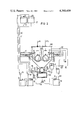
- FIG. 1 schematically illustrates one embodiment of a device for the galvanic deposition of aluminum which has been partially simplified
- FIG. 2 fundamentally illustrates another embodiment of such a device but which incorporates two galvanizing drums.
- the structure employed in the present invention has an advantage in that the galvanizing tank which is supplied with inert gas always contains electrolyte. In practice, only a tiny proportion thereof is discharged into the discharge container. Therefore, it is extremely advantageous for the volume of the discharge container flange attached to the connecting component to correspond approximately to that of the contents of the galvanizing drum.
- a simple construction consists in a tubular lockable connecting component that contains a commercially available ball valve.
- the problem of loading the galvanizing drum can be solved in a simple fashion.
- the transport device which extends into the interior of the galvanizing tank leads through a channel which rises obliquely upwards.
- the end of the channel is located outside the galvanizing tank, and is submerged into a container, filled with an inert liquid suitable for airlock use.
- the container which is filled with such inert liquid is tightly flange attached to the galvanizing tank, and the channel which accommodates the transport device rests in sealing fashion against the container of the liquid sluice by means of at least one partition wall.
- the discharge container expediently contains a perforated basket which can be removed through a laterially arranged hatch that can be closed so as to be air-tight.
- that part of the galvanizing drum which is submerged into the electrolyte is surrounded by two anodes which can be adjusted relative to one another in such a manner that they form a passage for the bulk goods which are to be emptied.
- the inert gas feed container is connected through valved ducts to the galvanizing tank, to the discharge container, and to the electrolyte feed container.
- the appropriate valves are controlled in such a manner as to form a closed inert gas cycle.
- the galvanizing tank includes two galvanizing drums so that two loads can be moved simultaneously under in part non-identical conditions.
- a galvanizing tank 1 is provided which is sealed in gas-tight fashion by a cover 2.
- the galvanizing tank 1 is provided with a heater unit 3 and possesses a discharge pipe 4 to which is flange attached a tubular connecting component 5 provided with a ball valve 6.
- Valve 6 can be actuated by means of a manual lever 7.
- the connecting component 5 is flange attached to a discharge container 8 which is fabricated as an unloading airlock and in which there is accommodated a perforated filling basket 9 having a sloping base 10.
- the filling basket 9 can be removed through hatch 11 which is arranged on the side of the discharge container 8 and which can be sealed in gas-tight fashion by means of a cover 12.
- a three-way valve 14 is attached to the base of the discharge container 8 through a pipeline 13 and is connected through a pipeline 15 to an electrolyte feed container 16 sealed in gas-tight fashion.
- the electrolyte feed container 16 is equipped with pressure relief valve 17.
- the three-way valve 14 is connected through a pipeline 18 and through a valve 19 to a container 20 into which can be discharged an inert liquid 21 used for flooding or flushing the discharge container 8.
- the pipeline 18 is also connected through a valve 22 and a pipeline 23 to a further container 24 into which can be discharged an inert liquid 25 which is used for washing the bulk goods in the discharge container 8.
- the two containers 20 and 24 are provided with pressure relief valves 26 and 27.
- the container 20 and 24 are arranged beneath the three-way valve 14 so that the inert liquids 21 and 25 can reach this point by means of the force of gravity.
- pumps 30 and 31 the inert liquids 21 and 25 can be pumped through pipelines 28 and 29 into feed container 32 and 33.
- a vaporizer 35 is connected into the pipeline 29 through a valve 34 and can be used to cleanse the inert liquid 25, used for washing purposes, of enriched electrolyte.
- the containers 32 and 33 are likewise equipped with pressure relief valves 36 and 37.
- the containers 32 and 33 are normally filled with inert liquids 21 and 25 as indicated by broken lines 38 and 39 which indicate the liquid level.
- the feed containers 32 and 33 are connected to the discharge container 8 via pipelines 40 and 41. Valves 42 and 43 which serve to control the inert liquids 21 and 25 are arranged in the pipelines 40 and 41.
- a loading airlock 45 which is constructed as a liquid seal is provided for loading the galvanizing drum 44 arranged in the galvanizing tank.
- the loading airlock 45 consists of a container 46 which contains an inert liquid 47, the level 48 thereof therein being indicated by a broken line.
- the container 46 is attached in gas-tight fashion to the galvanizing tank 1 by means of a flange 49.
- a channel 51 which rises obliquely upwards, is attached by means of a diaphragm 50, and in this channel a transport device in the form of a conveyor belt 52 leads into the interior of the galvanizing tank 1.
- the end 53 of the transport belt 52 terminates above an opening 54 in the galvanizing drum 44.
- the channel 51 is extended to such an extent that it is fully submerged into the inert liquid 47 so that the bulk goods which can be delivered by means of a further conveyor belt 55 reach the end of the conveyor belt 52 and from there are fed via the end 53 into the galvanizing drum 44.
- the conveyor belt 55 is fully submerged into the inert liquid 47.
- it can also be submerged obliquely from above into the inert liquid 47 so that the bulk goods can be placed more easily onto the conveyor belt 55.
- the conveyor belt 55 is loaded through an opening 56 in the container 46 which can be closed by means of a hatch cover 57.
- the diaphragm 50 is arranged in gas-tight fashion between the container 46 and the channel 51 and supports the channel 51.
- a plurality of diaphragms 50 can be provided. Therefore, that end of the channel 51 which extends into the interior of the galvanizing drum 1 can be introduced slackly into the interior of the galvanizing drum 1 through an opening 58. This quite substantially simplifies assembly.
- the galvanizing drum 44 has a generally hexagonal cross-section.
- the drum casing is perforated in known manner.
- the galvanizing drum 44 is rotatably mounted on shaft 59 in the tank 1.
- the galvanizing drum 44 is equipped with a gear rim 60 which engages with a gear wheel 61.
- the gear wheel 61 is driven by an electric motor (not shown).
- the opening 54 of the galvanizing drum 44 is closable by a cover 62.
- the cover 62 can be lifted by means of a lifting mechanism 63 which leads tightly through the cover 2 of the galvanizing tank 1 by means of guides 64.
- the lifting mechanism 63 can be moved both in the axial direction and about is axis of rotation 67.
- an unlocking mechanism (not shown in detail) with the aid of which the unlocking pins 69 arranged on the cover 62 can be operated.
- These unlocking pins 69 form a shape-locking connection with corresponding bores at the edge of the opening 54 of the galvanizing drum 44.
- the galvanizing drum 44 is surrounded by two anodes 70 arranged homologously, where the anode terminals 71 lead out of the galvanizing tank 1 through anode ducts 72.
- the anodes 70 can be adjusted towards the walls of the galvanizing tank 1 as indicated in broken lines. This exposes an opening 73 so that the contents of the galvanizing drum 44 can be emptied into the discharge container 8 through the discharge pipe 4.
- the shaft 59 is attached through a cable 74 composed of conductive material to a club-shaped cathode 75 which can be actively connected to the bulk goods 76 contained in the galvanizing drum 44.
- the shaft 59 is connected via a further electrical cable 77 to a cathode terminal 78 which leads through an opening 79 through the cover 2 of the galvanizing tank 1.
- the cover 2 of the galvanizing tank also possesses a pressure relief valve 80.
- an inert gas container 81 which is connected through a pipeline 82 and a valve 83 to the galvanizing tank 1, and through a pipeline 84 and a valve 85 to the electrolyte feed container 16.
- the inert gas container 81 is connected to the connecting component 5 through a further pipeline 86 and a valve 87.
- the electrolyte feed container 16 is connected via a pipeline 88 to the galvanizing tank 1 so that, when necessary, a pump 80 can be used to pump electrolyte into the galvanizing tank 1 to maintain therein a predetermined level 90 as indicated by the broken lines.
- the area of the container 46 behind the diaphragm 50 is connected to the electrolyte feed container 16 via a pipeline 91 and a valve 92.
- the container 46 is also equipped with a pressure relief valve 96.
- the discharge container 8 can either be ventilated or subjected to inert gas via the valve 94 and a pipeline 93.
- a valve 95 in the inert gas feed container 81 is needed for the inert gas, such as N 2 , requirement from a bottle.
- the description of the mode of operation of the device has been based on the assumption that the galvanizing tank 1 contains an aluminum electrolyte, and the galvanizing drum 44 assumes a position in which the opening 54, closed by the cover 62, is located below the lifting mechanism 63. It has further been assumed that all the valves are closed and the feed containers 32 and 33 contain inert liquid for flushing and for washing. Furthermore, it is assumed that the container 46 contains inert liquid 47 for sealing the loading airlock 45. Thus, the system is ready for operation.
- the galvanizing drum 44 is opened by lifting the cover 62 by means of the lifting mechanism 63.
- the lifting mechanism 63 is moved downwards in the direction of the arrow 66 towards the cover 62 which closes the opening 54 of the galvanizing drum 44.
- the galvanizing drum 44 is next rotated by 30° to the left into a starting position as illustrated in FIG. 1. Then, the cover 57 of the loading sluice 45 is opened.
- the valve 83 is opened to connect the galvanizing drum 1 to the inert gas feed container 81.
- the galvanizing drum 44 is loaded with bulk goods 76 by means of the conveyor belts 55 and 52 which have been set in motion.
- the inert gas which has been displaced out of the galvanizing tank 1 by the volume of the supplied bulk goods 76 flows through the valve 83 into the inert gas feed container 81.
- the inert gas feed container 81 serves for pressure compensation in the event of volumetric changes in the galvanizing tank 1, in the connecting component 5, and in the discharge container 8 of the unloading airlock 45.
- no inert gas is lost.
- the processes which must be carried out, and which will be described in detail below, can always be effected with 100% inert gas. Any moisture and air which may be drawn into the inert gas feed container 81 is chemically eliminated by triethyl aluminum.
- the galvanizing drum 44 is rotated by 30° in clockwise direction.
- the galvanizing drum 44 is closed with the cover 62 by lowering the lifting mechanism 63 and then rotating in the opposite direction as shown by the direction of the arrow 65 whereby the unlocking pinds 69 engage in shape-locking fashion into the assigned bores in the walls of the opening 54 of the galvanizing drum 44.
- the drum drive is switched on so that the galvanizing drum 44 is rotated by the gear wheel 61 and the gear rim 60 at an appropriate speed for the galvanization, and connection of the galvanization voltage to the cathode terminal 78 and to the anode terminals 71 is accomplished.
- the galvanizing current is disconnected, the anodes 70 are brought into the broken line position so that the opening 73 is formed, and the cover 62 of the galvanizing drum 44 is raised by the lifting mechanism 63 in the above described manner.
- the following processes are first carried out: By opening the valve 42, the discharge container 8 has been filled with inert liquid 21 and the air contained in the discharge container 8 has escaped via the open valve 94. Then, these respective valves are closed, and the valve 87 is opened to the inert gas feed container 81. Furthermore, the valve 19 is opened to the container 20, and the three-way valve 14 is adjusted in such manner that the flushing liquid can discharge from the discharge container 8 through the pipeline 18 into the container 20. Inert gas also flows from the inert gas feed container 81 into the discharge container 8 through the pipeline 86.
- the air in the container 20 is thus able to escape through the pressure relief valve 26.
- the end of the flooding process can consist, for example, of a level regulation, which has not been described in detail, however, but which may be conventional.
- the valves 19 and 87 and the three-way valve 14 are closed.
- the container 8 contains only inert gas from the inert gas feed container 81.
- the ball valve 6 is now opened so that electrolyte flows out of the galvanizing tank 1 through the connecting component 5 into the discharge container 8 and the displaced inert gas flows into the galvanizing tank 1.
- the valve 83 is opened.
- the drum is rotated by 180° into its emptying position so that the bulk goods 76 fall through the connecting component 5 into the filling basket 10 of the feed container 8.
- Electrolyte is now displaced out of the feed container 8 into the galvanizing tank 1 so that the discharge container 8 contains only very little electrolyte.
- the remaining quantity of electrolyte can be limited to a minimum.
- the three-way valve 14 is now adjusted in such a manner as to establish a connection from the discharge container 8 to the electrolyte feed container 16 and in fact via the pipelines 13 and 15.
- the valves 85 and 87 are opened so that the inert gas of the electrolyte feed container 16, which is subject to an inert gas atmosphere, can escape via the valve 85 to the inert gas feed container 81, whereas the volume of the discharged electrolyte in the discharge container is replaced by inert gas via the valve 87.
- the electrolyte feed container 16 always contains a 100% inert gas atmosphere.
- the electrolyte contained in the electrolyte feed container 16 is pumped back into the galvanizing tank 1 by the pump 89 and via the pipeline 88, and the electrolyte volume is replaced by inert gas via the valve 85.
- valve 43 is opened.
- the inert liquid 25 provided for washing purposes flows out of the feed container 33 via the pipeline 41 into the discharge container 8.
- the inert atmosphere in the discharge container 8 can flow via the valve 87 and the pipeline 86 into the inert gas feed container 81.
- the valve 43 is closed from the feed container 33.
- the three-way valve 14 is now set in such manner that the discharge container 8 can flow via pipelines 18 and 23 into the container 24 when the valve 22 is opened.
- the inert liquid 25 which is discharged from the discharge container 8 is replaced by air via the pipeline 93 when the valve 94 is opened.
- valve 22 and the three-way valve 14 are then closed.
- the discharge container 8 can be opened and the filling basket 9 together with the washed bulk goods 76 can be removed. It should be noted that the washing process can be repeated as often as desired in the described manner.
- the emptied filling basket 9 is returned to the discharge container 8 and the discharge container 9 is sealed in air-tight fashion when the cover 12 is placed in position.
- the valve 94 is open, if the valve 42 is opened, the discharge container 8 is flooded with inert liquid 21 from the feed container 32, as a result of which the displaced air can escape via the valve 94. Then, the valve 94 is closed, and inert gas is inlet into the discharge container 8 via the pipeline 86 past valve 87.
- the three-way valve 14 is now set in such manner that, via the pipeline 18 and the open valve 19, the washing liquid contained in the discharge container 8 can empty into the container 20, and the outlet liquid is replaced by inert gas via the valve 87.
- the starting state is now re-established.
- the inert liquids 21 and 25 are in the meantime conveyed back into the feed container 32 and 33 by means of the pumps 30 and 31 from the containers 20 and 24.
- the inert liquid 25 used for washing purposes is cleansed of enriched electrolyte by means of the vaporizer 35.
- the galvanizing drum 44 is returned to the position illustrated in FIG. 1 in readiness for the next galvanizing process and the anodes 70 are returned to the solid-line position shown in FIG. 1.
- FIG. 2 illustrates an embodiment in which two galvanizing drums 101 and 102 are accommodated in a galvanizing tank 100.
- a central anode 103 is fixed in position, the two outer anodes 104 and 105 can be externally adjusted so that the bulk goods which are to be galvanized can be discharged into a common discharge container 108 via a common connecting component 106 which contains a ball valve 107.
- the discharge container 108 contains a filling basket 109 for the withdrawal of the bulk goods following the removal of a cover 110.
- a separate loading device 111 and 112 designed in accordance with the exemplary embodiment shown in FIG. 1 is provided for each of the galvanizing drums 101 and 102.
- a cover 113 contains two lifting mechanisms 114 and 115 for the opening of the galvanizing drums 101 and 102, respectively.
- the control of the device illustrated in FIG. 2 is similar to that of the device shown in FIG. 1.
- the two galvanizing drums 101 and 102 can be loaded simultaneously or alternately, although the electrolyte from the electrolyte feed container 16 must be maintained via level monitors in the galvanizing tank 100. For this reason, idenitically functioning parts in FIG. 2 have been provided with the same references as in FIG. 1.
Landscapes
- Chemical & Material Sciences (AREA)
- Engineering & Computer Science (AREA)
- Chemical Kinetics & Catalysis (AREA)
- Electrochemistry (AREA)
- Materials Engineering (AREA)
- Metallurgy (AREA)
- Organic Chemistry (AREA)
- Electroplating Methods And Accessories (AREA)
- Coating With Molten Metal (AREA)
- Processing Of Solid Wastes (AREA)
- Electrical Discharge Machining, Electrochemical Machining, And Combined Machining (AREA)
- Electroplating And Plating Baths Therefor (AREA)
- Manufacture And Refinement Of Metals (AREA)
- Electrolytic Production Of Metals (AREA)
- Centrifugal Separators (AREA)
- Beans For Foods Or Fodder (AREA)
- Separation Using Semi-Permeable Membranes (AREA)
- Sorting Of Articles (AREA)
- Processing And Handling Of Plastics And Other Materials For Molding In General (AREA)
- Dental Preparations (AREA)
Applications Claiming Priority (2)
| Application Number | Priority Date | Filing Date | Title |
|---|---|---|---|
| DE3023129A DE3023129C2 (de) | 1980-06-20 | 1980-06-20 | Vorrichtung zum galvanischen Abscheiden von Aluminium |
| DE3023129 | 1980-06-20 |
Publications (1)
| Publication Number | Publication Date |
|---|---|
| US4360409A true US4360409A (en) | 1982-11-23 |
Family
ID=6105053
Family Applications (1)
| Application Number | Title | Priority Date | Filing Date |
|---|---|---|---|
| US06/269,490 Expired - Fee Related US4360409A (en) | 1980-06-20 | 1981-06-02 | Apparatus for the galvanic deposition of aluminum |
Country Status (12)
| Country | Link |
|---|---|
| US (1) | US4360409A (de) |
| EP (1) | EP0042503B1 (de) |
| JP (1) | JPS593560B2 (de) |
| AT (1) | ATE4511T1 (de) |
| BR (1) | BR8103882A (de) |
| CA (1) | CA1163600A (de) |
| DE (1) | DE3023129C2 (de) |
| DK (1) | DK151392C (de) |
| ES (1) | ES8205272A1 (de) |
| IE (1) | IE51615B1 (de) |
| NO (1) | NO154886C (de) |
| PT (1) | PT73225B (de) |
Cited By (7)
| Publication number | Priority date | Publication date | Assignee | Title |
|---|---|---|---|---|
| US4427518A (en) | 1981-07-10 | 1984-01-24 | Siemens Aktiengesellschaft | Electroplating device |
| US4460447A (en) * | 1982-09-29 | 1984-07-17 | Siemens Aktiengesellschaft | Apparatus for the galvanic deposition of aluminum |
| US4571291A (en) * | 1984-08-20 | 1986-02-18 | Alumatec, Inc. | Apparatus for the electrodeposition of metal |
| US4671862A (en) * | 1985-09-17 | 1987-06-09 | Siemens Aktiengesellschaft | Apparatus for mass electroplating of bulk goods |
| US4696728A (en) * | 1985-09-17 | 1987-09-29 | Siemens Aktiengesellschaft | Apparatus for mass electroplating of bulk goods |
| FR2796401A1 (fr) * | 1999-07-12 | 2001-01-19 | Wmv App Bau Gmbh Co Kg | Procede et appapreil pour le traitement electrochimique, en particulier pour le revetement electrochimique de pieces conductrices ou rendues conductrices, dans un recipient rempli d'un electrolyte |
| US20040256219A1 (en) * | 2001-07-28 | 2004-12-23 | Jorg Heller | Device for the electrodeposition of aluminum or aluminum alloys from organometallic electrolytes containing alkyl |
Families Citing this family (6)
| Publication number | Priority date | Publication date | Assignee | Title |
|---|---|---|---|---|
| DE3107101A1 (de) * | 1981-02-20 | 1982-09-09 | Schering Ag, 1000 Berlin Und 4619 Bergkamen | Vorrichtung und verfahren zur galvanischen metallabscheidung auf gegenstaenden, deren reinigung von anhaftenden oberflaechenbehandlungsmitteln sowie deren rueckgewinnung |
| DE3438316A1 (de) * | 1984-10-19 | 1985-10-10 | Alois 5202 Hennef Müller | Vorrichtung und verfahren zur nassentleerung einer transportablen galvaniktrommel |
| US4668367A (en) * | 1985-07-09 | 1987-05-26 | Siemens Aktiengesellschaft | Lock for loading and unloading goods into a treatment apparatus having a protective atmosphere |
| JPS62162498A (ja) * | 1986-01-11 | 1987-07-18 | エルム工業株式会社 | 書類つづり穴補強片貼付機構を備えた書類パンチ |
| CH694619A5 (de) | 1999-07-12 | 2005-04-29 | Wmv Appbau Gmbh & Co Kg | Verfahren und Vorrichtung zur elektrochemischen Behandlung. |
| CN106222701A (zh) * | 2016-07-29 | 2016-12-14 | 四川华索自动化信息工程有限公司 | 一种基于比较放大电路的铝电解用自动加料控制系统 |
Citations (2)
| Publication number | Priority date | Publication date | Assignee | Title |
|---|---|---|---|---|
| US3425926A (en) * | 1965-07-27 | 1969-02-04 | Kazuya Hojyo | Apparatus for automatically electroplating various articles with chromium |
| US4066515A (en) * | 1975-08-21 | 1978-01-03 | Siemens Aktiengesellschaft | Apparatus and method for the electrodepositing of aluminum |
Family Cites Families (2)
| Publication number | Priority date | Publication date | Assignee | Title |
|---|---|---|---|---|
| DE2506689A1 (de) * | 1975-02-14 | 1976-09-02 | Schering Ag | Automatische galvanisieranlage |
| DE2716805C3 (de) * | 1977-04-15 | 1979-10-31 | Siemens Ag, 1000 Berlin Und 8000 Muenchen | Vorrichtung zum galvanischen Abscheiden von Aluminium |
-
1980
- 1980-06-20 DE DE3023129A patent/DE3023129C2/de not_active Expired
-
1981
- 1981-06-01 EP EP81104182A patent/EP0042503B1/de not_active Expired
- 1981-06-01 AT AT81104182T patent/ATE4511T1/de not_active IP Right Cessation
- 1981-06-02 US US06/269,490 patent/US4360409A/en not_active Expired - Fee Related
- 1981-06-16 JP JP56092948A patent/JPS593560B2/ja not_active Expired
- 1981-06-17 ES ES503144A patent/ES8205272A1/es not_active Expired
- 1981-06-17 PT PT73225A patent/PT73225B/de unknown
- 1981-06-18 CA CA000380081A patent/CA1163600A/en not_active Expired
- 1981-06-19 IE IE1362/81A patent/IE51615B1/en unknown
- 1981-06-19 BR BR8103882A patent/BR8103882A/pt unknown
- 1981-06-19 DK DK272381A patent/DK151392C/da not_active IP Right Cessation
- 1981-06-19 NO NO812101A patent/NO154886C/no unknown
Patent Citations (2)
| Publication number | Priority date | Publication date | Assignee | Title |
|---|---|---|---|---|
| US3425926A (en) * | 1965-07-27 | 1969-02-04 | Kazuya Hojyo | Apparatus for automatically electroplating various articles with chromium |
| US4066515A (en) * | 1975-08-21 | 1978-01-03 | Siemens Aktiengesellschaft | Apparatus and method for the electrodepositing of aluminum |
Cited By (7)
| Publication number | Priority date | Publication date | Assignee | Title |
|---|---|---|---|---|
| US4427518A (en) | 1981-07-10 | 1984-01-24 | Siemens Aktiengesellschaft | Electroplating device |
| US4460447A (en) * | 1982-09-29 | 1984-07-17 | Siemens Aktiengesellschaft | Apparatus for the galvanic deposition of aluminum |
| US4571291A (en) * | 1984-08-20 | 1986-02-18 | Alumatec, Inc. | Apparatus for the electrodeposition of metal |
| US4671862A (en) * | 1985-09-17 | 1987-06-09 | Siemens Aktiengesellschaft | Apparatus for mass electroplating of bulk goods |
| US4696728A (en) * | 1985-09-17 | 1987-09-29 | Siemens Aktiengesellschaft | Apparatus for mass electroplating of bulk goods |
| FR2796401A1 (fr) * | 1999-07-12 | 2001-01-19 | Wmv App Bau Gmbh Co Kg | Procede et appapreil pour le traitement electrochimique, en particulier pour le revetement electrochimique de pieces conductrices ou rendues conductrices, dans un recipient rempli d'un electrolyte |
| US20040256219A1 (en) * | 2001-07-28 | 2004-12-23 | Jorg Heller | Device for the electrodeposition of aluminum or aluminum alloys from organometallic electrolytes containing alkyl |
Also Published As
| Publication number | Publication date |
|---|---|
| ES503144A0 (es) | 1982-06-01 |
| ATE4511T1 (de) | 1983-09-15 |
| DE3023129C2 (de) | 1982-04-15 |
| NO154886C (no) | 1987-01-07 |
| ES8205272A1 (es) | 1982-06-01 |
| NO812101L (no) | 1981-12-21 |
| JPS5743998A (en) | 1982-03-12 |
| BR8103882A (pt) | 1982-03-09 |
| DE3023129A1 (de) | 1982-01-14 |
| CA1163600A (en) | 1984-03-13 |
| DK272381A (da) | 1981-12-21 |
| IE811362L (en) | 1981-12-20 |
| PT73225B (de) | 1982-07-01 |
| EP0042503B1 (de) | 1983-08-24 |
| NO154886B (no) | 1986-09-29 |
| PT73225A (de) | 1981-07-01 |
| IE51615B1 (en) | 1987-01-21 |
| DK151392C (da) | 1988-05-16 |
| JPS593560B2 (ja) | 1984-01-24 |
| DK151392B (da) | 1987-11-30 |
| EP0042503A1 (de) | 1981-12-30 |
Similar Documents
| Publication | Publication Date | Title |
|---|---|---|
| US4360409A (en) | Apparatus for the galvanic deposition of aluminum | |
| CN1133225C (zh) | 用于对电化学电源再填充燃料的方法和装置 | |
| KR20230034232A (ko) | 처리 스테이션, 처리 플랜트, 및 피가공물을 처리하기 위한 방법 | |
| US4392936A (en) | Device for the galvanic deposition of aluminum | |
| CN217043219U (zh) | 用于对工件进行处理的处理设备 | |
| US4176034A (en) | Apparatus for the electrodeposition of aluminum | |
| US4427518A (en) | Electroplating device | |
| US4710410A (en) | Dual basket small parts coating apparatus | |
| KR20230033655A (ko) | 처리 스테이션, 처리 플랜트, 및 피가공물을 처리하기 위한 방법 | |
| US4702288A (en) | Apparatus for the pneumatic injection of pulverulent materials into a pressurized vessel, and its application to the injection of powered coal into a shaft furnace | |
| US4596636A (en) | Method for the electrodeposition of metal and method of workpiece pretreatment therefor | |
| US4460447A (en) | Apparatus for the galvanic deposition of aluminum | |
| CN100564611C (zh) | 金属物品的电镀镀敷方法和设备 | |
| US4363712A (en) | Device for galvanic precipitation of aluminum | |
| CN114853036A (zh) | 氟化锂/无水氟化氢的自动化混合生产方法 | |
| US4571291A (en) | Apparatus for the electrodeposition of metal | |
| US4415422A (en) | Apparatus for electro-depositing aluminum | |
| FR2796401A1 (fr) | Procede et appapreil pour le traitement electrochimique, en particulier pour le revetement electrochimique de pieces conductrices ou rendues conductrices, dans un recipient rempli d'un electrolyte | |
| US3606476A (en) | Fluidized lead shot conveyer | |
| US20040256219A1 (en) | Device for the electrodeposition of aluminum or aluminum alloys from organometallic electrolytes containing alkyl | |
| CN223069834U (zh) | 浸渍处理装置 | |
| CN215160968U (zh) | 酒水输送装置 | |
| CN219308670U (zh) | 一种可移动加料系统 | |
| FR2796400A1 (fr) | Procede et appareil pour le traitement electrochimique de pieces avec extraction separee des produits de decomposition de l'eau au niveau electrodes | |
| CN210313494U (zh) | 一种中药生产用灌装线 |
Legal Events
| Date | Code | Title | Description |
|---|---|---|---|
| AS | Assignment |
Owner name: SIEMENS AKTIENGESELLSCHAFT, BERLIN AND MUNICH, A C Free format text: ASSIGNMENT OF ASSIGNORS INTEREST.;ASSIGNORS:STOEGER, KLAUS;BIRKLE, SIEGFRIED;GEHRING, JOHANN;REEL/FRAME:003890/0481 Effective date: 19810521 |
|
| MAFP | Maintenance fee payment |
Free format text: PAYMENT OF MAINTENANCE FEE, 4TH YEAR, PL 96-517 (ORIGINAL EVENT CODE: M170); ENTITY STATUS OF PATENT OWNER: LARGE ENTITY Year of fee payment: 4 |
|
| FEPP | Fee payment procedure |
Free format text: PAYOR NUMBER ASSIGNED (ORIGINAL EVENT CODE: ASPN); ENTITY STATUS OF PATENT OWNER: LARGE ENTITY |
|
| MAFP | Maintenance fee payment |
Free format text: PAYMENT OF MAINTENANCE FEE, 8TH YEAR, PL 96-517 (ORIGINAL EVENT CODE: M171); ENTITY STATUS OF PATENT OWNER: LARGE ENTITY Year of fee payment: 8 |
|
| FEPP | Fee payment procedure |
Free format text: MAINTENANCE FEE REMINDER MAILED (ORIGINAL EVENT CODE: REM.); ENTITY STATUS OF PATENT OWNER: LARGE ENTITY |
|
| LAPS | Lapse for failure to pay maintenance fees | ||
| FP | Lapsed due to failure to pay maintenance fee |
Effective date: 19941123 |
|
| STCH | Information on status: patent discontinuation |
Free format text: PATENT EXPIRED DUE TO NONPAYMENT OF MAINTENANCE FEES UNDER 37 CFR 1.362 |