US4398809A - High speed catadioptric system - Google Patents
High speed catadioptric system Download PDFInfo
- Publication number
- US4398809A US4398809A US06/280,244 US28024481A US4398809A US 4398809 A US4398809 A US 4398809A US 28024481 A US28024481 A US 28024481A US 4398809 A US4398809 A US 4398809A
- Authority
- US
- United States
- Prior art keywords
- sub
- lens
- central portion
- main mirror
- field lens
- Prior art date
- Legal status (The legal status is an assumption and is not a legal conclusion. Google has not performed a legal analysis and makes no representation as to the accuracy of the status listed.)
- Expired - Lifetime
Links
Images
Classifications
-
- G—PHYSICS
- G02—OPTICS
- G02B—OPTICAL ELEMENTS, SYSTEMS OR APPARATUS
- G02B17/00—Systems with reflecting surfaces, with or without refracting elements
- G02B17/08—Catadioptric systems
- G02B17/0856—Catadioptric systems comprising a refractive element with a reflective surface, the reflection taking place inside the element, e.g. Mangin mirrors
-
- G—PHYSICS
- G02—OPTICS
- G02B—OPTICAL ELEMENTS, SYSTEMS OR APPARATUS
- G02B17/00—Systems with reflecting surfaces, with or without refracting elements
- G02B17/08—Catadioptric systems
- G02B17/0804—Catadioptric systems using two curved mirrors
- G02B17/0808—Catadioptric systems using two curved mirrors on-axis systems with at least one of the mirrors having a central aperture
-
- G—PHYSICS
- G02—OPTICS
- G02B—OPTICAL ELEMENTS, SYSTEMS OR APPARATUS
- G02B17/00—Systems with reflecting surfaces, with or without refracting elements
- G02B17/08—Catadioptric systems
- G02B17/0852—Catadioptric systems having a field corrector only
-
- G—PHYSICS
- G02—OPTICS
- G02B—OPTICAL ELEMENTS, SYSTEMS OR APPARATUS
- G02B17/00—Systems with reflecting surfaces, with or without refracting elements
- G02B17/08—Catadioptric systems
- G02B17/0884—Catadioptric systems having a pupil corrector
Definitions
- This invention relates to an improved high speed catadioptric system with a front lens, a main mirror lens with an unsilvered central portion, a counter mirror and a field lens system.
- High speed catadioptric systems with spherical faces are known. These systems, with only rare exceptions, are variations of the Mandler-type and have two or more front lenses, a Cassegrain mirror system and a field lens system. Such an objective is disclosed in F. I. Havlicek, L. Canzek: "Zum Korrigieren von Spiegelobjectiven", Deutsche Geodatician Kommission bei der Bayerischen Akademie dermaschineen, Erasmus A, Heft 42, Munchen 1963. Another embodiment with a relative aperture of 1:1.2 is shown in German DE-Patent 2 222 864. A large drawback of this lens type is the great zonal error of spheric aberration.
- a high speed mirror lens with good correction of the zonal error of spherical aberration is made known by Swiss CH-Patent 542 454 and by L. Canzek: “Lichtstarkes katadiopttechniks reiv", Optica Acta, No. 12, 1971 and No. 4, 1972.
- This lens consists of only one front lens with its silvered central back portion effective as counter mirror, a centrally bored main mirror lens and a field lens system. The system focus is within the objective, impeding general use.
- high refractive index glasses SF 3 and respectively SF 55 or LaF 23 must be used for the big optical elements, i.e. for the front lens and the main mirror lens.
- the front lens and main mirror lens must be manufactured from different types of glass.
- the well known advantages of high refractive index glasses for the correction of aberrations are in contrast to the drawbacks, namely low resistance to chemical attack, high specific gravity and a high cost. Lens manufacture from such glass is complicated and costly.
- high refractive index glasses are available where the said drawbacks are less pronounced, these glasses have a reduced transparency for the small wavelength (short-wave) part of the visible spectrum. But this spectral range is rather important for its use in optoelectronics, photography and for visual devices.
- More suitable glasses are provided for the front lens and the main mirror lens of two other embodiments from the above application. But this is brought about by a more expensive construction for these objectives have an additional medium sized lens arranged near to the counter mirror. Moreover the large sized optical elements are still made from different types of glass. The advantage of the more suitable glasses is thus counterbalanced by a more complicated and expensive construction.
- One object of this invention is to provide a high speed catadioptric system with great focal length and those lenses distant from the focus being made of the same type of glass in order to essentially eliminate the primary and secondary spectra and to make possible chromatic correction for a broad spectral range.
- Another object is to provide such an objective lens with simple construction and the same glass for the front and main mirror lens being less heavy, less expensive and above all more resistant to chemical attack than with known lens systems.
- the lens performance and in particular image forming properties should be at the same time at least as good as with known objectives.
- the optical system of this invention comprises, in accordance with the advance of the light rays a front lens, a main mirror lens, a counter mirror surface to the central portion of the front lens and a field lens system.
- the field lens system is composed of the dioptrically effective central portion of the main mirror lens and of lenses immediately adjacent to said central portion, both on the object and on the image side.
- the lens on the object side as well as the whole field lens system are convergent, whereas the image side component is divergent.
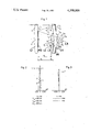
- FIG. 1 illustrates a schematic cross section of an embodiment of the present invention
- FIG. 3 shows the astigmatism of an objective according to claim 3 of the present invention.
- F is the speed of the system
- f is the focal length
- s' is the back focal distance
- All three examples each consist of a front lens L 1 , a main mirror lens M 1 , a counter mirror M 2 surfaced to the central portion of the front lens and a field lens system L 2 , L 3 , L 4 .
- the field lens system is composed of the unslivered central portion L 3 of the main mirror lens and additional lenses L 2 and L 4 adjacent to the main mirror lens respectively on its object and image side.
- the lenses in front and behind of the main mirror lens may be arranged each with a separate mount, but not necessarily so; they are advantageously cemented to the main mirror lens, as shown in FIG. 1.
- the said lenses may each comprise several components, but single elements are also sufficient, as shown in FIG. 1.
- the lens L 2 in front of the main mirror lens M 1 as well as the field lens system as a whole must be convergent in order to provide a good image quality even off axis.
- Catadioptric systems of this kind are mostly used in optoelectronics and in particular for night vision systems in conjunction with image intensifier or image converter tubes.
- the image intensifier tube of the third generation is distinguished over those of the first and second generation by its spectral sensitivity being shifted to the infrared range and by a cover glass being inserted in front of the cathode instead of the usual fiber plate (see I. P. Csorba: "Recent Advancements In The Field Of Image Intensification: The Generation 3 Wafer Tube", Applied Optics, No. 14, 1979).
- Objectives according to the present invention may be modified, as known in the art, for use with the cover glass.
- Such an embodiment is given by the above Example 3 and shown in FIG. 1 by the glass L 5 of thickness d 11 in dashed representation. But this embodiment may be used with intensifier tubes of all three generations, the only necessary modification for use with generation 1 and 2 tubes being to replace the cover glass by a plane plate of corresponding thickness.
- Glass of type LLF 1 may be replaced by another type of approximately equal suitability (e.g. K 7, LF 7 etc.) or front and main mirror lens may be made of two different glasses (for use with a more narrow spectral range), without changing the fundamental optical concept of the invention.
- Objective system lenses according to the present invention may also be manufactured from material suited for use within the UV or IR spectral range.
- Examples 1, 2 and 3 are distinguised over the state of the art by shape and rule of combination of the convergent and divergent elements of the field lens system L 2 , L 3 , L 4 , which has got a fundamentally new layout characteristic for the present invention. Only this novel approach has brought about fulfillment of the objects of the invention.
Landscapes
- Physics & Mathematics (AREA)
- General Physics & Mathematics (AREA)
- Optics & Photonics (AREA)
- Lenses (AREA)
- Non-Silver Salt Photosensitive Materials And Non-Silver Salt Photography (AREA)
Applications Claiming Priority (2)
| Application Number | Priority Date | Filing Date | Title |
|---|---|---|---|
| CH6155/80A CH651943A5 (de) | 1980-08-16 | 1980-08-16 | Katadioptrisches objektiv hoher oeffnung. |
| CH6155/80 | 1980-08-16 |
Publications (1)
| Publication Number | Publication Date |
|---|---|
| US4398809A true US4398809A (en) | 1983-08-16 |
Family
ID=4305155
Family Applications (1)
| Application Number | Title | Priority Date | Filing Date |
|---|---|---|---|
| US06/280,244 Expired - Lifetime US4398809A (en) | 1980-08-16 | 1981-07-06 | High speed catadioptric system |
Country Status (6)
| Country | Link |
|---|---|
| US (1) | US4398809A (de) |
| EP (1) | EP0046443B1 (de) |
| JP (1) | JPS5754912A (de) |
| AT (1) | ATE14163T1 (de) |
| CH (1) | CH651943A5 (de) |
| DE (1) | DE3171204D1 (de) |
Cited By (16)
| Publication number | Priority date | Publication date | Assignee | Title |
|---|---|---|---|---|
| RU2192027C1 (ru) * | 2001-03-28 | 2002-10-27 | Открытое акционерное общество "Красногорский завод им. С.А.Зверева" | Зеркально-линзовый объектив |
| US20060012885A1 (en) * | 2003-12-15 | 2006-01-19 | Carl Zeiss Smt Ag | Projection objective having a high aperture and a planar end surface |
| US20070091451A1 (en) * | 2003-12-19 | 2007-04-26 | Karl-Heinz Schuster | Microlithography projection objective with crystal lens |
| US7224520B2 (en) | 2004-09-28 | 2007-05-29 | Wavefront Research, Inc. | Compact fast catadioptric imager |
| US20070153398A1 (en) * | 2000-01-14 | 2007-07-05 | Carl Zeiss Stiftung | Microlithographic reduction projection catadioptric objective |
| US20070195423A1 (en) * | 2004-01-14 | 2007-08-23 | Vladimir Kamenov | Method of determining lens materials for a projection exposure apparatus |
| US20080019022A1 (en) * | 2004-09-28 | 2008-01-24 | Wavefront Research, Inc. | Compact fast catadioptric imager |
| US20080112927A1 (en) * | 2006-10-23 | 2008-05-15 | Genegrafts Ltd. | Cells and methods utilizing same for modifying the electrophysiological function of excitable tissues |
| US7385756B2 (en) | 2004-01-14 | 2008-06-10 | Carl Zeiss Smt Ag | Catadioptric projection objective |
| US20080186567A1 (en) * | 2004-01-14 | 2008-08-07 | Carl Zeiss Smt Ag | Catadioptric projection objective |
| RU2333518C2 (ru) * | 2006-03-31 | 2008-09-10 | Казенное предприятие "Центральное конструкторское бюро "Арсенал" | Зеркально-линзовый объектив |
| US8199400B2 (en) | 2004-01-14 | 2012-06-12 | Carl Zeiss Smt Gmbh | Catadioptric projection objective |
| US8363315B2 (en) | 2004-04-08 | 2013-01-29 | Carl Zeiss Smt Gmbh | Catadioptric projection objective with mirror group |
| US8913316B2 (en) | 2004-05-17 | 2014-12-16 | Carl Zeiss Smt Gmbh | Catadioptric projection objective with intermediate images |
| EA021664B1 (ru) * | 2012-12-12 | 2015-08-31 | Научно-Производственное Унитарное Предприятие "Научно-Технический Центр "Лэмт" Беломо" | Зеркально-линзовый объектив |
| US12164178B2 (en) * | 2020-05-04 | 2024-12-10 | Largan Precision Co., Ltd. | Imaging optical lens assembly, imaging apparatus and electronic device |
Families Citing this family (2)
| Publication number | Priority date | Publication date | Assignee | Title |
|---|---|---|---|---|
| CH668322A5 (de) * | 1985-07-24 | 1988-12-15 | Zumbach Electronic Ag | Vorrichtung mit einem telezentrischen, f-theta-korrigierten objektiv fuer kontaktloses messen und verwendung dieser vorrichtung. |
| DE4429377C2 (de) * | 1994-08-12 | 1997-07-17 | Frank Gallert | Katadioptrisches Objektiv |
Citations (5)
| Publication number | Priority date | Publication date | Assignee | Title |
|---|---|---|---|---|
| US3711184A (en) * | 1971-04-12 | 1973-01-16 | Kollsman Instr Corp | Large catadioptric objective |
| US4061420A (en) * | 1976-05-06 | 1977-12-06 | Questar Corporation | Catadioptric lens system |
| EP0002647A1 (de) * | 1977-12-08 | 1979-06-27 | KERN & CO. AG Werke für Präzisionsmechanik Optik und Elektronik | Kompaktes katadioptrisches Objektiv grosser Lichtstärke |
| US4165151A (en) * | 1976-06-19 | 1979-08-21 | Canon Kabushiki Kaisha | Two-reflecting catadioptric optical system |
| US4264136A (en) * | 1978-08-25 | 1981-04-28 | Minolta Camera Kabushiki Kaisha | Catadioptric lens system |
Family Cites Families (2)
| Publication number | Priority date | Publication date | Assignee | Title |
|---|---|---|---|---|
| DE1274812B (de) * | 1963-02-12 | 1968-08-08 | Canon Camera Co | Lichtstarkes katadioptrisches System des Cassegrain Typs |
| US3632190A (en) * | 1968-09-24 | 1972-01-04 | Nippon Kogaku Kk | Catadioptric telephoto objective lens system |
-
1980
- 1980-08-16 CH CH6155/80A patent/CH651943A5/de not_active IP Right Cessation
-
1981
- 1981-07-06 US US06/280,244 patent/US4398809A/en not_active Expired - Lifetime
- 1981-07-29 JP JP56117862A patent/JPS5754912A/ja active Pending
- 1981-08-03 AT AT81810312T patent/ATE14163T1/de not_active IP Right Cessation
- 1981-08-03 EP EP81810312A patent/EP0046443B1/de not_active Expired
- 1981-08-03 DE DE8181810312T patent/DE3171204D1/de not_active Expired
Patent Citations (5)
| Publication number | Priority date | Publication date | Assignee | Title |
|---|---|---|---|---|
| US3711184A (en) * | 1971-04-12 | 1973-01-16 | Kollsman Instr Corp | Large catadioptric objective |
| US4061420A (en) * | 1976-05-06 | 1977-12-06 | Questar Corporation | Catadioptric lens system |
| US4165151A (en) * | 1976-06-19 | 1979-08-21 | Canon Kabushiki Kaisha | Two-reflecting catadioptric optical system |
| EP0002647A1 (de) * | 1977-12-08 | 1979-06-27 | KERN & CO. AG Werke für Präzisionsmechanik Optik und Elektronik | Kompaktes katadioptrisches Objektiv grosser Lichtstärke |
| US4264136A (en) * | 1978-08-25 | 1981-04-28 | Minolta Camera Kabushiki Kaisha | Catadioptric lens system |
Cited By (41)
| Publication number | Priority date | Publication date | Assignee | Title |
|---|---|---|---|---|
| US20070153398A1 (en) * | 2000-01-14 | 2007-07-05 | Carl Zeiss Stiftung | Microlithographic reduction projection catadioptric objective |
| US7859748B2 (en) | 2000-01-14 | 2010-12-28 | Carl Zeiss Smt Gmbh | Microlithographic reduction projection catadioptric objective |
| RU2192027C1 (ru) * | 2001-03-28 | 2002-10-27 | Открытое акционерное общество "Красногорский завод им. С.А.Зверева" | Зеркально-линзовый объектив |
| US7466489B2 (en) | 2003-12-15 | 2008-12-16 | Susanne Beder | Projection objective having a high aperture and a planar end surface |
| US20060012885A1 (en) * | 2003-12-15 | 2006-01-19 | Carl Zeiss Smt Ag | Projection objective having a high aperture and a planar end surface |
| US7782538B2 (en) | 2003-12-15 | 2010-08-24 | Carl Zeiss Smt Ag | Projection objective having a high aperture and a planar end surface |
| US20090059385A1 (en) * | 2003-12-15 | 2009-03-05 | Carl Zeiss Smt Ag | Projection objective having a high aperture and a planar end surface |
| US20070091451A1 (en) * | 2003-12-19 | 2007-04-26 | Karl-Heinz Schuster | Microlithography projection objective with crystal lens |
| US7755839B2 (en) | 2003-12-19 | 2010-07-13 | Carl Zeiss Smt Ag | Microlithography projection objective with crystal lens |
| US8416490B2 (en) | 2004-01-14 | 2013-04-09 | Carl Zeiss Smt Gmbh | Catadioptric projection objective |
| US8730572B2 (en) | 2004-01-14 | 2014-05-20 | Carl Zeiss Smt Gmbh | Catadioptric projection objective |
| US7463422B2 (en) | 2004-01-14 | 2008-12-09 | Carl Zeiss Smt Ag | Projection exposure apparatus |
| US20080186567A1 (en) * | 2004-01-14 | 2008-08-07 | Carl Zeiss Smt Ag | Catadioptric projection objective |
| US20080310014A1 (en) * | 2004-01-14 | 2008-12-18 | Carl Zeiss Smt Ag | Catadioptric projection objective |
| US7385756B2 (en) | 2004-01-14 | 2008-06-10 | Carl Zeiss Smt Ag | Catadioptric projection objective |
| US7672047B2 (en) | 2004-01-14 | 2010-03-02 | Carl Zeiss Smt Ag | Catadioptric projection objective |
| US7679821B2 (en) | 2004-01-14 | 2010-03-16 | Carl Zeiss Smt Ag | Catadioptric projection objective |
| US9772478B2 (en) | 2004-01-14 | 2017-09-26 | Carl Zeiss Smt Gmbh | Catadioptric projection objective with parallel, offset optical axes |
| US8908269B2 (en) | 2004-01-14 | 2014-12-09 | Carl Zeiss Smt Gmbh | Immersion catadioptric projection objective having two intermediate images |
| US8804234B2 (en) | 2004-01-14 | 2014-08-12 | Carl Zeiss Smt Gmbh | Catadioptric projection objective including an aspherized plate |
| US20100253999A1 (en) * | 2004-01-14 | 2010-10-07 | Carl Zeiss Smt Ag | Catadioptric projection objective |
| US20070195423A1 (en) * | 2004-01-14 | 2007-08-23 | Vladimir Kamenov | Method of determining lens materials for a projection exposure apparatus |
| US7869122B2 (en) | 2004-01-14 | 2011-01-11 | Carl Zeiss Smt Ag | Catadioptric projection objective |
| US8199400B2 (en) | 2004-01-14 | 2012-06-12 | Carl Zeiss Smt Gmbh | Catadioptric projection objective |
| US8208199B2 (en) | 2004-01-14 | 2012-06-26 | Carl Zeiss Smt Gmbh | Catadioptric projection objective |
| US8208198B2 (en) | 2004-01-14 | 2012-06-26 | Carl Zeiss Smt Gmbh | Catadioptric projection objective |
| US8289619B2 (en) | 2004-01-14 | 2012-10-16 | Carl Zeiss Smt Gmbh | Catadioptric projection objective |
| US8339701B2 (en) | 2004-01-14 | 2012-12-25 | Carl Zeiss Smt Gmbh | Catadioptric projection objective |
| US8355201B2 (en) | 2004-01-14 | 2013-01-15 | Carl Zeiss Smt Gmbh | Catadioptric projection objective |
| US8363315B2 (en) | 2004-04-08 | 2013-01-29 | Carl Zeiss Smt Gmbh | Catadioptric projection objective with mirror group |
| US8913316B2 (en) | 2004-05-17 | 2014-12-16 | Carl Zeiss Smt Gmbh | Catadioptric projection objective with intermediate images |
| US9019596B2 (en) | 2004-05-17 | 2015-04-28 | Carl Zeiss Smt Gmbh | Catadioptric projection objective with intermediate images |
| US9134618B2 (en) | 2004-05-17 | 2015-09-15 | Carl Zeiss Smt Gmbh | Catadioptric projection objective with intermediate images |
| US9726979B2 (en) | 2004-05-17 | 2017-08-08 | Carl Zeiss Smt Gmbh | Catadioptric projection objective with intermediate images |
| US7224520B2 (en) | 2004-09-28 | 2007-05-29 | Wavefront Research, Inc. | Compact fast catadioptric imager |
| US20080019022A1 (en) * | 2004-09-28 | 2008-01-24 | Wavefront Research, Inc. | Compact fast catadioptric imager |
| US7701647B2 (en) | 2004-09-28 | 2010-04-20 | Wavefront Research, Inc. | Compact fast catadioptric imager |
| RU2333518C2 (ru) * | 2006-03-31 | 2008-09-10 | Казенное предприятие "Центральное конструкторское бюро "Арсенал" | Зеркально-линзовый объектив |
| US20080112927A1 (en) * | 2006-10-23 | 2008-05-15 | Genegrafts Ltd. | Cells and methods utilizing same for modifying the electrophysiological function of excitable tissues |
| EA021664B1 (ru) * | 2012-12-12 | 2015-08-31 | Научно-Производственное Унитарное Предприятие "Научно-Технический Центр "Лэмт" Беломо" | Зеркально-линзовый объектив |
| US12164178B2 (en) * | 2020-05-04 | 2024-12-10 | Largan Precision Co., Ltd. | Imaging optical lens assembly, imaging apparatus and electronic device |
Also Published As
| Publication number | Publication date |
|---|---|
| EP0046443B1 (de) | 1985-07-03 |
| JPS5754912A (en) | 1982-04-01 |
| EP0046443A1 (de) | 1982-02-24 |
| CH651943A5 (de) | 1985-10-15 |
| ATE14163T1 (de) | 1985-07-15 |
| DE3171204D1 (en) | 1985-08-08 |
Similar Documents
| Publication | Publication Date | Title |
|---|---|---|
| US4398809A (en) | High speed catadioptric system | |
| US2500017A (en) | Apochromatic telescope objectives and systems including same | |
| US4124798A (en) | Optical viewing apparatus | |
| US4189211A (en) | Wide angle telecentric projection lens assembly | |
| US2520635A (en) | Optical system | |
| US3278752A (en) | Wide angle optical system having a telecentric stop and an interference filter | |
| US3355234A (en) | Four component microscope objective | |
| US3529888A (en) | Catadioptric optical system for telescopes and the like | |
| US2718173A (en) | High intensity five component photographic objective | |
| US2530397A (en) | Anastigmatic lens | |
| US4349249A (en) | Compound lens | |
| US4456343A (en) | High speed catadioptric objective lens system | |
| US5668671A (en) | Dioptric lens system | |
| US4392710A (en) | Optical apparatus | |
| US3486805A (en) | Ultra-achromatic fluorite silica triplet lens system | |
| US3438695A (en) | High speed catadioptric optical system of cassegrain type | |
| US2327947A (en) | Optical objective | |
| US2846923A (en) | High speed objective lens with anastigmatically flattened field | |
| US2576011A (en) | Catadioptric optical system | |
| GB2269024A (en) | Optical system having at least one tilted Mangin mirror | |
| Wynne | Field correctors for parabolic mirrors | |
| US2520633A (en) | Optical system | |
| US3119892A (en) | Catadioptric system | |
| US2986972A (en) | Ultraviolet copying objective lens | |
| US4280757A (en) | Objective lens system for microscopes |
Legal Events
| Date | Code | Title | Description |
|---|---|---|---|
| STCF | Information on status: patent grant |
Free format text: PATENTED CASE |
|
| MAFP | Maintenance fee payment |
Free format text: PAYMENT OF MAINTENANCE FEE, 4TH YEAR, PL 96-517 (ORIGINAL EVENT CODE: M170); ENTITY STATUS OF PATENT OWNER: LARGE ENTITY Year of fee payment: 4 |
|
| FEPP | Fee payment procedure |
Free format text: PAYOR NUMBER ASSIGNED (ORIGINAL EVENT CODE: ASPN); ENTITY STATUS OF PATENT OWNER: LARGE ENTITY |
|
| MAFP | Maintenance fee payment |
Free format text: PAYMENT OF MAINTENANCE FEE, 8TH YEAR, PL 96-517 (ORIGINAL EVENT CODE: M171); ENTITY STATUS OF PATENT OWNER: LARGE ENTITY Year of fee payment: 8 |
|
| MAFP | Maintenance fee payment |
Free format text: PAYMENT OF MAINTENANCE FEE, 12TH YEAR, LARGE ENTITY (ORIGINAL EVENT CODE: M185); ENTITY STATUS OF PATENT OWNER: LARGE ENTITY Year of fee payment: 12 |
|
| FEPP | Fee payment procedure |
Free format text: PAT HLDR NO LONGER CLAIMS SMALL ENT STAT AS INDIV INVENTOR (ORIGINAL EVENT CODE: LSM1); ENTITY STATUS OF PATENT OWNER: LARGE ENTITY |