US4399554A - Method and apparatus for inspecting engine head valve retainer assemblies for missing keys - Google Patents
Method and apparatus for inspecting engine head valve retainer assemblies for missing keys Download PDFInfo
- Publication number
- US4399554A US4399554A US06/180,131 US18013180A US4399554A US 4399554 A US4399554 A US 4399554A US 18013180 A US18013180 A US 18013180A US 4399554 A US4399554 A US 4399554A
- Authority
- US
- United States
- Prior art keywords
- edge
- array
- symmetry
- pixel
- center
- Prior art date
- Legal status (The legal status is an assumption and is not a legal conclusion. Google has not performed a legal analysis and makes no representation as to the accuracy of the status listed.)
- Expired - Lifetime
Links
Images



Classifications
-
- G—PHYSICS
- G06—COMPUTING OR CALCULATING; COUNTING
- G06T—IMAGE DATA PROCESSING OR GENERATION, IN GENERAL
- G06T7/00—Image analysis
- G06T7/0002—Inspection of images, e.g. flaw detection
- G06T7/0004—Industrial image inspection
- G06T7/0008—Industrial image inspection checking presence/absence
-
- G—PHYSICS
- G06—COMPUTING OR CALCULATING; COUNTING
- G06T—IMAGE DATA PROCESSING OR GENERATION, IN GENERAL
- G06T2207/00—Indexing scheme for image analysis or image enhancement
- G06T2207/30—Subject of image; Context of image processing
- G06T2207/30108—Industrial image inspection
- G06T2207/30164—Workpiece; Machine component
Definitions
- This invention relates to a method and apparatus for automatically inspecting valve spring assemblies on engine heads and, more particularly, to inspecting such assemblies for the presence of both valve spring cap keys during the engine assembly process.
- a V-8 engine has two engine heads and eight valve spring assemblies per head.
- the valve spring assemblies comprise a valve, spring, spring retainer and two half rings called keys.
- the spring To insert the valve spring assemblies into the engine head, the spring must be compressed so that the keys can be placed around the valve stem notch. When the spring is released, the keys are firmly held in place. If one key should pop out as the spring is released, the other key will temporarily hold the assembly together. Because of human errors, the manual inspection operation performed after engine head assembly is less than perfect, and some percentage of the assembled engines do not contain both keys on each of the potentially eight valve spring assemblies of an engine head. Missing valve retainer keys can cause production delays and increase cost if they are discovered late in the assembly stage or during the engine testing phase. If they are not detected at all, the missing keys can lead to serious engine damage in the field.
- a shuttle conveyor transfers the head between stations along the assembly line in approximately one second.
- the engine remains at each station for an eight second dwell time while assembly operations are performed.
- there are significant variations in the reflectances of different valve assemblies and the intensity distribution of typical assemblies is not bi-modal. For these reasons, thresholding techniques are not very useful in separating regions of the image or in locating the center of the assembly in the image.
- a computer vision system for inspecting valve spring assemblies which is capable of inspecting for missing keys within the nine second cycle time of the existing engine head conveyor.
- the inspection for missing keys is based on the observation that the keys are always brighter than the hole which results when a key is missing and from the further observation that typical valve spring assembly images subjected to an edge operation show strong circular patterns which permit a determination of the center of the assembly by a convolution technique.
- a missing key may be detected.
- the system includes a computer which monitors the position of the engine head conveyor and inputs data from a solid state camera representing a digitized image of each valve spring assembly as the engine head passes the camera.
- the computer is programmed to utilize the intensity data provided by the camera to construct an edge array which is convolved with itself to locate the center of the assembly in the digitized image. After the center is located, on analysis of the intensity profile along the circumference of a circle of known radius is performed to determine if a key is missing. If a missing valve retainer key is detected, the engine head is removed from the conveyor prior to further assembly operations.
- FIGS. 1a and 1b are sectional and top views, respectively, of a typical valve spring assembly
- FIG. 2 is a block diagram of the apparatus of the present invention.
- FIG. 3 is an overall flow chart of the inspection system operation
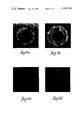
- FIGS. 4a-4d are digitized pictures of a portion of a valve spring assembly representing gray scale data, edge magnitude data, thresholded thinned edge data and edge mask data respectively.
- FIG. 5 shows a pixel neighborhood useful in describing the edge finding operation
- FIGS. 6a and 6b show the results of applying a convolution process to an image edge array to locate the axes of symmetry of the array.
- FIGS. 7a and 7b are intensity profiles along a circle of predetermined radius from the center of an assembly having both keys present (7a) and of an assembly having one key missing (7b).
- a conventional valve spring assembly comprises a valve (not shown) attached to a valve stem 12 which is biased in one direction by springs 14 and 16.
- One end of the springs 14 and 16 engage a valve spring retainer 18 which is coupled to the stem 12 by two keys 20 and 22 which have a projection engaging a corresponding notch in the stem 12.
- an engine head generally indicated by the numeral 24 contains a plurality of valve spring assemblies and is mounted on a conveyor 26 which moves the head 24 past a 64-element solid-state line camera 28.
- a conveyor position encoder 30 is attached directly to the conveyor or geared to the conveyor drive mechanism to keep track of the conveyor's position. Each time the conveyor 26 has moved a small increment of distance, the encoder 30 emits a pulse. The accumulation of these pulses permits identification of the conveyor position. Since the engine head is located fairly precisely on the conveyor and the locations of the valve spring assemblies on the head are known within a certain tolerance, the encoder output provides a source for locating the spring assemblies relative to the camera 28.
- a computer 32 such as the PDP 11/34, is responsive to the output of the encoder 30 and through an interface 34 inputs data from the camera 28 corresponding to 64-line pictures of each valve spring assembly as it passes through the field of view of the camera 28.
- the valve spring assembly is illuminated by a light source 36.
- the camera 28 is free-running but the picture data is input to the computer 32 only upon a command which is based on position of the engine head as input from the encoder 30. Once a region of the assembly, just slightly larger than the key area, enters the field of view of the camera, data corresponding to 64-line pictures, each picture containing 64 intensity values, is sequentially input and stored in a 64 ⁇ 64 memory array of the computer 32.
- the data is analyzed by the computer 32 to determine whether a valve retainer key is missing from any one of the eight assemblies of the engine head. The analysis is made during the eight second interval that the head is at the next assembly station.
- FIG. 3 A flow chart of the overall system operation is shown in FIG. 3. Once the 64 ⁇ 64 intensity array for each valve assembly (eight for the example shown) resides in the computer memory each array is processed in sequence. A digitized picture of a region of a typical valve spring assembly, just slightly larger than the key area with 16 gray levels, is shown in FIG. 4a. An edge operation is applied to every pixel in the gray level picture to identify pixels between regions of different light intensity "I”. With reference to FIG. 5, the gradient or edge magnitude "D" at point "P" is calculated using the Sobel edge operator except that the usual square root operation is approximated by a faster absolute value operation. Thus,
- FIG. 4b showing the edge magnitude
- a thinning or non-maximum suppression operation is applied to every pixel.
- each pixel is separated into two classes--horizontal or vertical--depending upon whether
- the thinned edge data is then subjected to a thresholding operation, which identifies those pixels that are edge pixels as ones having an edge magnitude greater than a predetermined fixed threshold.
- a threshold could be calculated from the thinned edge distribution or the convolution method could be modified to work with non-binary data.
- Applying a fixed threshold to the thinned edge array results in a binary array identifying the the edge pixels of the digitized image as shown in FIG. 4c.
- the center of symmetry of the array of edge pixels is the intersection of the vertical and horizontal axes of symmetry of the array. These axes are determined by convolving the edge pixels on the left with those on the right for each of a plurality of vertical axes and convolving the edge pixels above with those below for each of a plurality of horizontal axes.
- the convolution process involves counting the number of pairs of edge points which are equidistant from a potential axis of symmetry.
- FIGS. 6a and 6b The results of a convolution of a typical edge pixel array for X and Y values within ten pixels of the expected center are shown in FIGS. 6a and 6b.
- the verification involves translating the center of a model edge mask such as shown in FIG. 4d into coincidence with the center of the assembly as determined during the convolution of the edge array. If a good fit is not obtained, the verification test fails. The "goodness" of the fit is simply the total number of mask and image edge points that have the same pixel location.
- a profile of the intensity array through the center of key location is analyzed.
- the location of the keys relative to the center of the assembly is known so that the analysis involves a consideration of the intensity values at pixel locations on the circumference of a circle of known radius from the center of the assembly obtained from the convolution operation.
- the intensity profile for an image with both keys present is shown in FIG. 7a, and with one key missing in FIG. 7b.
- the profile is analyzed by determining the percentage of pixels with intensity values greater than a fixed threshold equal to 4, as shown by dotted lines in FIGS. 7a and 7b.
- the percentage of bright pixels must be greater than B MIN and less than B MAX . Satisfactory results are obtained when B MIN equals 82% and B MAX equals 99%.
- the computer notifies a rejection device and the head is rejected.
- an overall check of all assembly centers may be made to ensure that they are consistent with the head geometry. This can be accomplished by fitting a straight line to the eight assembly centers and rejecting the head if any assembly center is too far from the line. A test for deviations along the direction of motion may be made, if desired, by comparing assembly center positions with the median assembly center position.
Landscapes
- Engineering & Computer Science (AREA)
- Quality & Reliability (AREA)
- Computer Vision & Pattern Recognition (AREA)
- Physics & Mathematics (AREA)
- General Physics & Mathematics (AREA)
- Theoretical Computer Science (AREA)
- Investigating Materials By The Use Of Optical Means Adapted For Particular Applications (AREA)
- Image Analysis (AREA)
- Length Measuring Devices By Optical Means (AREA)
Priority Applications (2)
| Application Number | Priority Date | Filing Date | Title |
|---|---|---|---|
| US06/180,131 US4399554A (en) | 1980-08-21 | 1980-08-21 | Method and apparatus for inspecting engine head valve retainer assemblies for missing keys |
| CA000373634A CA1179426A (fr) | 1980-08-21 | 1981-03-23 | Methode et dispositif de depistage de l'absence des clavettes de retenue des soupapes sur culasse de moteur |
Applications Claiming Priority (1)
| Application Number | Priority Date | Filing Date | Title |
|---|---|---|---|
| US06/180,131 US4399554A (en) | 1980-08-21 | 1980-08-21 | Method and apparatus for inspecting engine head valve retainer assemblies for missing keys |
Publications (1)
| Publication Number | Publication Date |
|---|---|
| US4399554A true US4399554A (en) | 1983-08-16 |
Family
ID=22659319
Family Applications (1)
| Application Number | Title | Priority Date | Filing Date |
|---|---|---|---|
| US06/180,131 Expired - Lifetime US4399554A (en) | 1980-08-21 | 1980-08-21 | Method and apparatus for inspecting engine head valve retainer assemblies for missing keys |
Country Status (2)
| Country | Link |
|---|---|
| US (1) | US4399554A (fr) |
| CA (1) | CA1179426A (fr) |
Cited By (24)
| Publication number | Priority date | Publication date | Assignee | Title |
|---|---|---|---|---|
| US4466122A (en) * | 1981-02-17 | 1984-08-14 | Sidney Auerbach | Discriminator for pattern recognition |
| US4611292A (en) * | 1982-10-06 | 1986-09-09 | Hitachi, Ltd. | Robot vision system |
| US4649621A (en) * | 1986-02-21 | 1987-03-17 | Artos Engineering Company | Wire processing apparatus having control means |
| US4731853A (en) * | 1984-03-26 | 1988-03-15 | Hitachi, Ltd. | Three-dimensional vision system |
| US4885784A (en) * | 1985-07-10 | 1989-12-05 | Fuji Electric Company Ltd. | System for binary encoding a picture |
| US4918627A (en) * | 1986-08-04 | 1990-04-17 | Fmc Corporation | Computer integrated gaging system |
| US4920429A (en) * | 1989-01-24 | 1990-04-24 | International Business Machines | Exposure compensation for a line scan camera |
| US4928313A (en) * | 1985-10-25 | 1990-05-22 | Synthetic Vision Systems, Inc. | Method and system for automatically visually inspecting an article |
| US4945766A (en) * | 1989-09-08 | 1990-08-07 | General Motors Corporation | Method and apparatus for ultrasonic inspection |
| US5132791A (en) * | 1990-09-25 | 1992-07-21 | Ball Corporation | Optical sheet inspection system |
| US5420971A (en) * | 1994-01-07 | 1995-05-30 | Panasonic Technologies, Inc. | Image edge finder which operates over multiple picture element ranges |
| US5615287A (en) * | 1994-12-02 | 1997-03-25 | The Regents Of The University Of California | Image compression technique |
| US5754677A (en) * | 1994-10-25 | 1998-05-19 | Fuji Machine Mfg. Co., Ltd. | Image processing apparatus |
| US6597806B1 (en) | 1999-01-13 | 2003-07-22 | Fuji Machine Mfg. Co., Ltd. | Image processing method and apparatus |
| US6640002B1 (en) | 1998-06-10 | 2003-10-28 | Fuji Machine Mfg. Co., Ltd. | Image processing apparatus |
| US6661931B1 (en) | 1999-12-03 | 2003-12-09 | Fuji Machine Mfg. Co., Ltd. | Image processing method, image processing system, and modifying-data producing method |
| USRE38559E1 (en) | 1984-12-20 | 2004-07-27 | Orbotech Ltd | Automatic visual inspection system |
| WO2007131326A1 (fr) * | 2006-05-12 | 2007-11-22 | Alberta Research Council Inc. | Système et procédé pour détecter une pièce de machine endommagée ou manquante |
| US8819723B1 (en) | 2000-04-27 | 2014-08-26 | The Directv Group, Inc. | System and method for brokering auxiliary data broadcasting services |
| US10011975B2 (en) | 2015-02-13 | 2018-07-03 | Esco Corporation | Monitoring ground-engaging products for earth working equipment |
| US10024033B2 (en) | 2013-11-25 | 2018-07-17 | Esco Corporation | Wear part monitoring |
| US10337656B2 (en) * | 2015-10-27 | 2019-07-02 | Ford Global Technologies, Llc | Quick connect with visual indicator |
| US11461886B2 (en) * | 2019-07-10 | 2022-10-04 | Syncrude Canada Ltd. | Monitoring wear of double roll crusher teeth by digital video processing |
| US11712768B1 (en) * | 2022-04-14 | 2023-08-01 | R.P. Gatta, Inc | Engine cylinder valve spring keeper installation system |
Citations (2)
| Publication number | Priority date | Publication date | Assignee | Title |
|---|---|---|---|---|
| US4146924A (en) * | 1975-09-22 | 1979-03-27 | Board Of Regents For Education Of The State Of Rhode Island | System for visually determining position in space and/or orientation in space and apparatus employing same |
| US4296474A (en) * | 1977-09-06 | 1981-10-20 | Deere & Company | Inspection system and apparatus therefor |
-
1980
- 1980-08-21 US US06/180,131 patent/US4399554A/en not_active Expired - Lifetime
-
1981
- 1981-03-23 CA CA000373634A patent/CA1179426A/fr not_active Expired
Patent Citations (2)
| Publication number | Priority date | Publication date | Assignee | Title |
|---|---|---|---|---|
| US4146924A (en) * | 1975-09-22 | 1979-03-27 | Board Of Regents For Education Of The State Of Rhode Island | System for visually determining position in space and/or orientation in space and apparatus employing same |
| US4296474A (en) * | 1977-09-06 | 1981-10-20 | Deere & Company | Inspection system and apparatus therefor |
Non-Patent Citations (4)
| Title |
|---|
| Branaman, "Recent Applications of Electronic Vision to Noncontact Automatic Inspection", Proc. of the S.P.I.E., vol. 182, Apr., 1979, pp. 102-107. * |
| Milgram, "Edge Linking Using Thresholding", Proc. of the S.P.I.E., vol. 205, Aug., 1979, pp. 139-144. * |
| Olsztyn et al., "An Application of Computer Vision to a Simulated Assembly Task", Proc. of the First Int. Joint Conf. on Pattern Rec., 1973, pp. 505-513. * |
| Sumida et al., "Industrial Visual System by a Symmetry Operator", Proc. of the S.P.I.E., vol. 182, Apr., 1979, pp. 22-29. * |
Cited By (41)
| Publication number | Priority date | Publication date | Assignee | Title |
|---|---|---|---|---|
| US4466122A (en) * | 1981-02-17 | 1984-08-14 | Sidney Auerbach | Discriminator for pattern recognition |
| US4611292A (en) * | 1982-10-06 | 1986-09-09 | Hitachi, Ltd. | Robot vision system |
| US4731853A (en) * | 1984-03-26 | 1988-03-15 | Hitachi, Ltd. | Three-dimensional vision system |
| USRE38559E1 (en) | 1984-12-20 | 2004-07-27 | Orbotech Ltd | Automatic visual inspection system |
| US4885784A (en) * | 1985-07-10 | 1989-12-05 | Fuji Electric Company Ltd. | System for binary encoding a picture |
| US4928313A (en) * | 1985-10-25 | 1990-05-22 | Synthetic Vision Systems, Inc. | Method and system for automatically visually inspecting an article |
| US4649621A (en) * | 1986-02-21 | 1987-03-17 | Artos Engineering Company | Wire processing apparatus having control means |
| DE3636487A1 (de) * | 1986-02-21 | 1987-08-27 | Artos Engineering Co | Drahtverarbeitungsvorrichtung mit einer kontrolleinrichtung |
| US4918627A (en) * | 1986-08-04 | 1990-04-17 | Fmc Corporation | Computer integrated gaging system |
| US4920429A (en) * | 1989-01-24 | 1990-04-24 | International Business Machines | Exposure compensation for a line scan camera |
| US4945766A (en) * | 1989-09-08 | 1990-08-07 | General Motors Corporation | Method and apparatus for ultrasonic inspection |
| US5132791A (en) * | 1990-09-25 | 1992-07-21 | Ball Corporation | Optical sheet inspection system |
| US5420971A (en) * | 1994-01-07 | 1995-05-30 | Panasonic Technologies, Inc. | Image edge finder which operates over multiple picture element ranges |
| US5754677A (en) * | 1994-10-25 | 1998-05-19 | Fuji Machine Mfg. Co., Ltd. | Image processing apparatus |
| US5911001A (en) * | 1994-10-25 | 1999-06-08 | Fuji Machine Mfg. Co., Ltd. | Image processing apparatus |
| US5615287A (en) * | 1994-12-02 | 1997-03-25 | The Regents Of The University Of California | Image compression technique |
| US6640002B1 (en) | 1998-06-10 | 2003-10-28 | Fuji Machine Mfg. Co., Ltd. | Image processing apparatus |
| US6597806B1 (en) | 1999-01-13 | 2003-07-22 | Fuji Machine Mfg. Co., Ltd. | Image processing method and apparatus |
| US6661931B1 (en) | 1999-12-03 | 2003-12-09 | Fuji Machine Mfg. Co., Ltd. | Image processing method, image processing system, and modifying-data producing method |
| US8819723B1 (en) | 2000-04-27 | 2014-08-26 | The Directv Group, Inc. | System and method for brokering auxiliary data broadcasting services |
| US20100142759A1 (en) * | 2006-05-12 | 2010-06-10 | Alberta Research Council Inc. | A system and a method for detecting a damaged or missing machine part |
| WO2007131326A1 (fr) * | 2006-05-12 | 2007-11-22 | Alberta Research Council Inc. | Système et procédé pour détecter une pièce de machine endommagée ou manquante |
| US8411930B2 (en) | 2006-05-12 | 2013-04-02 | Alberta Research Council Inc. | System and a method for detecting a damaged or missing machine part |
| US10683642B2 (en) | 2013-11-25 | 2020-06-16 | Esco Group Llc | Wear part monitoring |
| US10697154B2 (en) | 2013-11-25 | 2020-06-30 | Esco Group Llc | Wear part monitoring |
| US10024033B2 (en) | 2013-11-25 | 2018-07-17 | Esco Corporation | Wear part monitoring |
| US10689832B2 (en) | 2013-11-25 | 2020-06-23 | Esco Group Llc | Wear part monitoring |
| US10689833B2 (en) | 2013-11-25 | 2020-06-23 | Esco Group Llc | Wear part monitoring |
| US10612213B2 (en) | 2015-02-13 | 2020-04-07 | Esco Group Llc | Monitoring ground-engaging products for earth working equipment |
| US10669698B2 (en) | 2015-02-13 | 2020-06-02 | Esco Group Llc | Monitoring ground-engaging products for earth working equipment |
| US10633831B2 (en) | 2015-02-13 | 2020-04-28 | Esco Group Llc | Monitoring ground-engaging products for earth working equipment |
| US10633832B2 (en) | 2015-02-13 | 2020-04-28 | Esco Group Llc | Monitoring ground-engaging products for earth working equipment |
| US10011975B2 (en) | 2015-02-13 | 2018-07-03 | Esco Corporation | Monitoring ground-engaging products for earth working equipment |
| US10760247B2 (en) | 2015-02-13 | 2020-09-01 | Esco Group Llc | Monitoring ground-engaging products for earth working equipment |
| US10787792B2 (en) | 2015-02-13 | 2020-09-29 | Esco Group Llc | Monitoring ground-engaging products for earth working equipment |
| US11851848B2 (en) | 2015-02-13 | 2023-12-26 | Esco Group Llc | Monitoring ground-engaging products for earth working equipment |
| US12104359B2 (en) | 2015-02-13 | 2024-10-01 | Esco Group Llc | Monitoring ground-engaging products for earth working equipment |
| US10337656B2 (en) * | 2015-10-27 | 2019-07-02 | Ford Global Technologies, Llc | Quick connect with visual indicator |
| US11415253B2 (en) | 2015-10-27 | 2022-08-16 | Ford Global Technologies, Llc | Quick connect with visual indicator |
| US11461886B2 (en) * | 2019-07-10 | 2022-10-04 | Syncrude Canada Ltd. | Monitoring wear of double roll crusher teeth by digital video processing |
| US11712768B1 (en) * | 2022-04-14 | 2023-08-01 | R.P. Gatta, Inc | Engine cylinder valve spring keeper installation system |
Also Published As
| Publication number | Publication date |
|---|---|
| CA1179426A (fr) | 1984-12-11 |
Similar Documents
| Publication | Publication Date | Title |
|---|---|---|
| US4399554A (en) | Method and apparatus for inspecting engine head valve retainer assemblies for missing keys | |
| CN110596129B (zh) | 一种基于图像采集的片状玻璃边缘瑕疵检测系统 | |
| US6381366B1 (en) | Machine vision methods and system for boundary point-based comparison of patterns and images | |
| JP3041090B2 (ja) | 外観検査装置 | |
| US5305391A (en) | Method of and apparatus for inspecting bottle or the like | |
| US4658428A (en) | Image recognition template generation | |
| CN117309766B (zh) | 一种产品表面缺陷的视觉检测方法及系统 | |
| CN106780473B (zh) | 一种磁环缺陷多目视觉检测方法及系统 | |
| US20040247171A1 (en) | Image processing method for appearance inspection | |
| CN119554980A (zh) | 基于机械臂的多目视觉汽车法兰盘螺纹检测装置和方法 | |
| CN110856847A (zh) | 一种基于智能视觉的电容字符检测方法及装置 | |
| US7684610B2 (en) | Rotating prism component inspection system | |
| CN119217388B (zh) | 一种视觉校正设备拧紧位置系统及其方法 | |
| CN111833350A (zh) | 机器视觉检测方法与系统 | |
| US6219434B1 (en) | Maxicode locating method | |
| JP3627249B2 (ja) | 画像処理装置 | |
| JP5778685B2 (ja) | ボールグリッドアレイデバイスの位置合わせ及び検査のためのシステム及び方法 | |
| CN111583176B (zh) | 一种基于图像的防雷模拟盘元件故障检测方法及系统 | |
| Todd | Advanced vision systems for computer-integrated manufacture Part II | |
| Perkins | Using circular symmetry and intensity profiles for computer vision inspection | |
| US20010033328A1 (en) | System and method for automatically inspecting an array of periodic elements | |
| JPH05203584A (ja) | ワーク表面特徴量検出装置 | |
| JPH0688789A (ja) | 画像中の濃度変動構成画素抽出方法および濃度変動塊判定方法 | |
| KR20200057286A (ko) | 실러의 토출상태 검사방법 | |
| RU2323492C2 (ru) | Способ обнаружения поверхностных дефектов цилиндрических объектов |
Legal Events
| Date | Code | Title | Description |
|---|---|---|---|
| STCF | Information on status: patent grant |
Free format text: PATENTED CASE |