US4402153A - Cartridge load for a revolver - Google Patents
Cartridge load for a revolver Download PDFInfo
- Publication number
- US4402153A US4402153A US06/251,730 US25173081A US4402153A US 4402153 A US4402153 A US 4402153A US 25173081 A US25173081 A US 25173081A US 4402153 A US4402153 A US 4402153A
- Authority
- US
- United States
- Prior art keywords
- ring
- cartridge
- cartridges
- lugs
- seats
- Prior art date
- Legal status (The legal status is an assumption and is not a legal conclusion. Google has not performed a legal analysis and makes no representation as to the accuracy of the status listed.)
- Expired - Fee Related
Links
- 229920003002 synthetic resin Polymers 0.000 claims description 6
- 239000000057 synthetic resin Substances 0.000 claims description 6
- 239000000463 material Substances 0.000 claims description 3
- 238000010276 construction Methods 0.000 claims 1
- 238000002347 injection Methods 0.000 abstract description 4
- 239000007924 injection Substances 0.000 abstract description 4
- 238000005192 partition Methods 0.000 description 8
- 238000010304 firing Methods 0.000 description 3
- 238000001746 injection moulding Methods 0.000 description 2
- 238000004519 manufacturing process Methods 0.000 description 2
- 230000000717 retained effect Effects 0.000 description 2
- 230000003313 weakening effect Effects 0.000 description 2
- DOSMHBDKKKMIEF-UHFFFAOYSA-N 2-[3-(diethylamino)-6-diethylazaniumylidenexanthen-9-yl]-5-[3-[3-[4-(1-methylindol-3-yl)-2,5-dioxopyrrol-3-yl]indol-1-yl]propylsulfamoyl]benzenesulfonate Chemical compound C1=CC(=[N+](CC)CC)C=C2OC3=CC(N(CC)CC)=CC=C3C(C=3C(=CC(=CC=3)S(=O)(=O)NCCCN3C4=CC=CC=C4C(C=4C(NC(=O)C=4C=4C5=CC=CC=C5N(C)C=4)=O)=C3)S([O-])(=O)=O)=C21 DOSMHBDKKKMIEF-UHFFFAOYSA-N 0.000 description 1
- 238000004873 anchoring Methods 0.000 description 1
- 239000011324 bead Substances 0.000 description 1
- 210000003414 extremity Anatomy 0.000 description 1
- 210000003811 finger Anatomy 0.000 description 1
- 230000006872 improvement Effects 0.000 description 1
- 230000001939 inductive effect Effects 0.000 description 1
- 230000037431 insertion Effects 0.000 description 1
- 238000003780 insertion Methods 0.000 description 1
- 230000007246 mechanism Effects 0.000 description 1
- 210000001331 nose Anatomy 0.000 description 1
- 238000009527 percussion Methods 0.000 description 1
- -1 polyethylene) ring Polymers 0.000 description 1
- 210000003813 thumb Anatomy 0.000 description 1
- 230000007704 transition Effects 0.000 description 1
Images

Classifications
-
- F—MECHANICAL ENGINEERING; LIGHTING; HEATING; WEAPONS; BLASTING
- F41—WEAPONS
- F41A—FUNCTIONAL FEATURES OR DETAILS COMMON TO BOTH SMALLARMS AND ORDNANCE, e.g. CANNONS; MOUNTINGS FOR SMALLARMS OR ORDNANCE
- F41A9/00—Feeding or loading of ammunition; Magazines; Guiding means for the extracting of cartridges
- F41A9/82—Reloading or unloading of magazines
- F41A9/83—Apparatus or tools for reloading magazines with unbelted ammunition, e.g. cartridge clips
- F41A9/84—Clips
- F41A9/85—Clips for reloading revolver-type magazines
Definitions
- Our present invention relates to a cartridge load for a revolver and to a device facilitating the loading of a revolver by holding the cartridges thereof in a predetermined spaced apart relationship.
- This ring can be preloaded with the cartridges so that, upon the complete firing of the cartridges of the revolver, the spent cartridges can be removed as a unit and a fresh package of cartridges inserted as a unit.
- the loading device is constituted as a strip or belt having pockets corresponding in number to the rounds, which may be received in the cylinder of the revolver, with a spacing between them corresponding to the spacing between these rounds.
- the belt or strip can be rolled so that the bullet ends of the cartridges can be inserted into the respective bores of the cylinder and the strip or belt is then drawn away to release the cartridges in succession so that the latter can be pressed further into the respective bores.
- the pocket-defining webs can bear one upon another to ensure the cylindrical pattern of the package which is retained by providing one end of the belt with a tab and the other end of the belt with a loop engageable by the tab to retain the package in place.
- the projecting portions of the cartridges of the package are inserted into the respective cylinder bores and the cylinder swung out of its normal position in the revolver, the tab is tugged to release it, and the belt is pulled away in the manner previously described, thereby inducing the cylinder to rotate as each pocket releases the respective cartridge.
- Each released cartridge can be pressed into place or can fall into place.
- the strip or belt can be reloaded at a later time.
- the pockets generally engage the body of the cartridge casing, which is cylindrical, between the flange or rim and the bullet over a length which is at least sufficient to ensure parallelity of the cartridges in the loading package.
- Loading packages of this latter type have various disadvantages which have been discovered with experience utilizing them.
- the hook-and-eye closure of the package may be released in normal handling operations, causing the package to open and constituting a manipulation problem.
- Another object of the invention is to provide an improved loading device which facilitates the loading of the cylinder of a revolver.
- the one-piece device as a closed ring having a grip on one side thereof, the ring having at least one weakened portion constituting a preferred break region which retains the ring in its closed position when the package is intact, but upon a tug on the grip, ruptures to allow the grip to withdraw the loading device as a unit and release the cartridges.
- the one-piece rings of the present invention can have resilient protuberances which spring into these grooves as the cartridges are thrust into the seats to retain the cartridges in a manner analogous to that used with the injection molding in our aforementioned patent.
- each seat or aperture extends in the excess of 180° around the respective cartridge and at least two protuberances are provided on opposite sides of the seat.
- the pockets of the ring, constituting cartridge sets, are preferably open inwardly toward the axis.
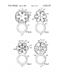
- FIG. 1 is an elevational view of a cartridge package for a revolver in accordance with an embodiment of the invention, showing the ring receiving one of the cartridges;
- FIGS. 2-7 are similar views of other embodiments of the loading device, illustrating units into which the cartridges can be inserted or which can be injection molded onto the cartridges.
- the cartridge package of the present invention can be used with a revolver whose cylinder or drum has a plurality of angularly equispaced bores each adapted to accommodate a respective cartridge and successively alignable with the barrel and hammer of the weapon. While the disks or rims of the present invention have six pockets or seats in which respective cartridges are received and hence the cartridge package is adapted for use with a six-shot revolver, the number of such seats can vary depending upon the number of bores in the revolver cylinder.
- the revolver cylinder can be swung out for loading and unloading.
- FIG. 1 a cartridge can be seen (from its bottom or rim 1) to have a primer or percussion cap 2 adapted to be struck by the revolver hammer.
- the cartridges are held in the package by a synthetic resin (e.g. polyethylene) ring or disk which, upon engagement by the user, can be pulled away as is the case with the loading strip or belt previously mentioned.
- a synthetic resin e.g. polyethylene
- the one-piece or unitary synthetic resin disk can be injection molded onto the cartridges and can be provided with weakened or breakaway points 5 which also serve to connect the arcuate members extending partly around each cartridge in an annular configuration.
- Another weakened zone in the form of a notch 12 is provided between a circular grip ring 3 and the other end of the synthetic resin element.
- the grip 3 forms the transition between one of these arcuate members and a ligature 5 at the weakening notch 12.
- the package shown in FIG. 1 is inserted into the rear of an outwardly swung cylinder of the revolver so that at least the bullet ends of each of the cartridges is received in respective bore or cylinder, the insertion being perpendicular to the plane of the paper in FIG. 1.
- the ring 3 is thereupon gripped and tugged away by the right hand while the weapon is held in the left hand, the grip being engaged between the thumb and ring finger.
- the weapon which can also be a tilting-magazine revolver which can be broken open for reloading, is held with its barrel turned downwardly and the ring 3 is pulled away from the drum.
- the loading disk breaks first in the region of the notch 12, freeing the cartridge directly adjacent to grip ring 3 and allowing the arcuate portions 4 to be successively drawn away as the cylinder rotates thereby releasing the cartridges.
- the cartridges then can drop or be pressed home into the respective bores.
- the grip and attached portions of the loading disk can then be discarded and the cylinder swung back into place.
- the loading disk of FIG. 1 thus consists of two circumferentially continuous but interconnected rings, the one being the gripping ring 3 while the other is a ring 8 formed with internally open seats or pockets 9 in which the cartridges are accommodated.
- the ring 8 is formed with a split 11 which is bridged by one of the connecting webs 5 forming a weakened zone at which the ring 8 can be broken apart.
- the separating walls between the seats or pockets 9 are formed at their inner extremities with inwardly diverging lugs 10' to resiliently hold the cartridges in the respective pockets.
- the two lugs of each separating wall can be passed to a collective width which does not exceed the smallest distance between neighboring cartridges. In FIG. 1 these ligatures are shown as they would lie in engagement with the cartridges.
- the lugs can be connected as shown at 10 in broken lines in this figure.
- the split 11 is formed in the partition wall closest to the ring 3 and extends into the recess or groove forming notch 12 of the cartridge ring 8.
- a projection 12' from the gripping ring extends slightly into the recess 12 and a further weakened web 5' bridges the wall of the recess and the projection.
- the lugs 10 upon withdrawal of the partition walls, are simply bent inwardly during this operation so that there is no danger of tearing. Since the pockets 9 are open inwardly and the cartridges are elastically held by the lugs 10, the cartridge package can be accommodated to various models of revolver as to different spacing of the cartidges.
- FIG. 2 differs from that of FIG. 1 in that the ring 108 formed with the seats 109 for the individual cartridges has its lugs 110 inwardly convergent, rather than divergent and bridged by intentional-break webs 105 which, upon application of a tug to the ring 3 break apart as the cartridges are individually released.
- the ring 608 has its seats 609 closed inwardly by a further ring 616 to which the lugs 610 and 610' reach and to which they are connected by intentional-break or weakened zones 605.
- each seat 9, 109, 209, 309, 409 and 609 is provided with at least one pair of oppositely inwardly projecting molded protuberances 6, 106, 206, 306, 406, 606 which engage in the ejector groove at the base of the cartridge and grip the latter when a cartridge is inserted into the seat in a direction perpendicular to the plane of the disk.
- a similar function is provided by the protuberances 506 in the embodiment of FIG. 7.
- one of the lugs, e.g. 610', adjacent the slit 11 can be fixed rigidly to the ring 3 and the inner ring 616.
- FIGS. 4 through 7 show loading units of various configurations which have in common the fact that the gripping ring 203 may be drawn radially away from the package rather than tangentially as represented by the arrows A in these Figures. When the cartridges holder is turned away, therefore, no rotation of the cylinder is necessary or occurs.
- the ring is connected by two relatively thin ligatures 13 to a pair of arcuate seat-forming members 208 which are interconnected by the weakened webs 205 at a gap 211, the remaining seats being represented at 209. All of the seats and pockets are spaced apart by partition walls which, as in the embodiment of FIGS. 1-3, have inwardly flaring resilient lugs 210 between adjoining seats or inwardly converging lugs for each seat.
- the inner walls 14 of the pockets 209 are connected to the ligatures 13 by intentional-rupture web 205'.
- FIG. 5 functions in a similar fashion and has the ring 203 connected directly to the arcuate portions 314 forming the seats or pockets 309 with their flaring lugs 310 between them.
- the two sections 308' and 308" of the cartridge ring adjoin at the gap 311 at which they are interconnected by the intentional-rupture web 305.
- a tearing band 15 reaches from the ring 203 to the web 305 so that a tug upon the grip ring 203 pulls the strip 15 away and breaks the cartridge ring at the gap 311 so that the unit can be withdrawn from the array of cartridges.
- FIG. 6 which is generally similar to that of FIG.
- the cartridge ring 408 is formed by the arcuate portions directly while the partition walls 410' between the seats or pockets 409 reach inwardly in a star configuration and are connected by intentional-break webs 405 with the strip 415.
- the strip 415 is connected to the remote arcuate members 408' and 408" by weakening notches 407, these members being bridged, moreover, by an intentional-break web 405'.
- the tear strip 415 breaks loose first, whereupon the gap 411 opens and the unit can be withdrawn.
- the ring 203 is connected to a tension or tear strip 515 which forms one of the walls defining the pockets 509 receiving the individual cartridges.
- the other walls 510" are connected at weak junctions 505 with an inner ring 515' split at the gap 511 and connected to the members 508' and 508" defining this gap by an intentional-break web 505'.
- the gap 511 can be spanned by another such web 505".
- the ring 515' When the ring 203 is gripped and pulled away from the array for cartridges, the ring 515' first breaks loose and collapses inwardly, whereupon the gap 511 opens to release the cartridges.
- all of the loading devices shown can be injection molded directly around the cartridges or can be filled with the cartridges by axially inserting them into the respective pockets.
- the devices are effective for various weapon types, leave no pieces of material within the array of cartridges or on the cylinder, and provide packages of high stability before the units are torn apart.
- the units can also be pressed or bonded to the cartridges by the application of heat and pressure which can be effected during the swaging of the shell casing or other operations in the manufacture of the cartridge.
Landscapes
- Engineering & Computer Science (AREA)
- General Engineering & Computer Science (AREA)
- Packaging Of Annular Or Rod-Shaped Articles, Wearing Apparel, Cassettes, Or The Like (AREA)
Applications Claiming Priority (2)
| Application Number | Priority Date | Filing Date | Title |
|---|---|---|---|
| AT2052/80 | 1980-04-16 | ||
| AT0205280A AT364979B (de) | 1980-04-16 | 1980-04-16 | Ladehilfe aus kunststoff fuer revolver |
Publications (1)
| Publication Number | Publication Date |
|---|---|
| US4402153A true US4402153A (en) | 1983-09-06 |
Family
ID=3526741
Family Applications (1)
| Application Number | Title | Priority Date | Filing Date |
|---|---|---|---|
| US06/251,730 Expired - Fee Related US4402153A (en) | 1980-04-16 | 1981-04-07 | Cartridge load for a revolver |
Country Status (3)
| Country | Link |
|---|---|
| US (1) | US4402153A (de) |
| AT (1) | AT364979B (de) |
| DE (1) | DE3110672A1 (de) |
Cited By (12)
| Publication number | Priority date | Publication date | Assignee | Title |
|---|---|---|---|---|
| US4771561A (en) * | 1987-09-21 | 1988-09-20 | Shimon Waiser | Revolver using changeable cylinders |
| US5621998A (en) * | 1995-11-01 | 1997-04-22 | Norgaard; Charles | Speed loader |
| US5719348A (en) * | 1996-01-16 | 1998-02-17 | Blount, Inc. | Component holder for cartridge reloading |
| US6189254B1 (en) * | 1995-03-02 | 2001-02-20 | Arthur R. Steitz | Magazine cartridge loading device |
| USD448061S1 (en) | 2000-10-08 | 2001-09-18 | Michael Leard | Revolver speed loader |
| US9702647B2 (en) | 2015-10-28 | 2017-07-11 | Vulcan Ballistic Products, LLC | Speed loaders for loading cartridges in revolver cylinders |
| US9835396B1 (en) * | 2016-12-06 | 2017-12-05 | Michael Sherman | Speed-loading device and method for storing and releasing cartridges into multi-chamber firearm |
| US10209018B1 (en) * | 2017-10-04 | 2019-02-19 | Chason Yaxley | Cartridge speed loader for use with a revolver cylinder barrel |
| US10222156B2 (en) | 2017-04-26 | 2019-03-05 | Vulcan Ballistic Products, LLC | Speed loaders and assemblies for loading cartridges in revolver cylinders |
| USD845425S1 (en) * | 2018-01-29 | 2019-04-09 | Chason Yaxley | Speed loader for a revolver style firearm |
| US10612875B1 (en) * | 2017-03-31 | 2020-04-07 | Richard Darin Roe | Revolver reloading apparatus and method of use |
| US11644259B1 (en) | 2021-11-28 | 2023-05-09 | Jordan Kristomas Kennedy | Systems and methods for a segmented speed loader |
Citations (7)
| Publication number | Priority date | Publication date | Assignee | Title |
|---|---|---|---|---|
| US913393A (en) * | 1908-05-18 | 1909-02-23 | Mahlon J Kellogg | Revolver-loader. |
| GB398690A (en) * | 1932-12-19 | 1933-09-21 | Thomas Aloysius Milmore | Revolver loaders |
| US1969817A (en) * | 1933-04-03 | 1934-08-14 | Thomas A Milmore | Rapid revolver loader |
| US3213559A (en) * | 1964-04-27 | 1965-10-26 | Matich Donald | Loading device for revolvers |
| DE2259610A1 (de) * | 1972-12-06 | 1974-06-12 | Stammel Heinz Josef | Schnell-lader fuer revolver |
| US4254571A (en) * | 1978-11-29 | 1981-03-10 | Kurt Peter | Cartridge load for a revolver |
| US4325198A (en) * | 1978-04-27 | 1982-04-20 | Gerhard Muck | Cartridge load for revolvers |
-
1980
- 1980-04-16 AT AT0205280A patent/AT364979B/de not_active IP Right Cessation
-
1981
- 1981-03-19 DE DE19813110672 patent/DE3110672A1/de not_active Withdrawn
- 1981-04-07 US US06/251,730 patent/US4402153A/en not_active Expired - Fee Related
Patent Citations (7)
| Publication number | Priority date | Publication date | Assignee | Title |
|---|---|---|---|---|
| US913393A (en) * | 1908-05-18 | 1909-02-23 | Mahlon J Kellogg | Revolver-loader. |
| GB398690A (en) * | 1932-12-19 | 1933-09-21 | Thomas Aloysius Milmore | Revolver loaders |
| US1969817A (en) * | 1933-04-03 | 1934-08-14 | Thomas A Milmore | Rapid revolver loader |
| US3213559A (en) * | 1964-04-27 | 1965-10-26 | Matich Donald | Loading device for revolvers |
| DE2259610A1 (de) * | 1972-12-06 | 1974-06-12 | Stammel Heinz Josef | Schnell-lader fuer revolver |
| US4325198A (en) * | 1978-04-27 | 1982-04-20 | Gerhard Muck | Cartridge load for revolvers |
| US4254571A (en) * | 1978-11-29 | 1981-03-10 | Kurt Peter | Cartridge load for a revolver |
Cited By (14)
| Publication number | Priority date | Publication date | Assignee | Title |
|---|---|---|---|---|
| US4771561A (en) * | 1987-09-21 | 1988-09-20 | Shimon Waiser | Revolver using changeable cylinders |
| US6189254B1 (en) * | 1995-03-02 | 2001-02-20 | Arthur R. Steitz | Magazine cartridge loading device |
| US5621998A (en) * | 1995-11-01 | 1997-04-22 | Norgaard; Charles | Speed loader |
| US5719348A (en) * | 1996-01-16 | 1998-02-17 | Blount, Inc. | Component holder for cartridge reloading |
| US5767433A (en) * | 1996-01-16 | 1998-06-16 | Blount, Inc. | Component holder for cartridge reloading |
| USD448061S1 (en) | 2000-10-08 | 2001-09-18 | Michael Leard | Revolver speed loader |
| US9702647B2 (en) | 2015-10-28 | 2017-07-11 | Vulcan Ballistic Products, LLC | Speed loaders for loading cartridges in revolver cylinders |
| US9835396B1 (en) * | 2016-12-06 | 2017-12-05 | Michael Sherman | Speed-loading device and method for storing and releasing cartridges into multi-chamber firearm |
| US10612875B1 (en) * | 2017-03-31 | 2020-04-07 | Richard Darin Roe | Revolver reloading apparatus and method of use |
| US10222156B2 (en) | 2017-04-26 | 2019-03-05 | Vulcan Ballistic Products, LLC | Speed loaders and assemblies for loading cartridges in revolver cylinders |
| US10563942B2 (en) | 2017-04-26 | 2020-02-18 | Vulcan Ballistic Products, LLC | Speed loaders and assemblies for loading cartridges in revolver cylinders |
| US10209018B1 (en) * | 2017-10-04 | 2019-02-19 | Chason Yaxley | Cartridge speed loader for use with a revolver cylinder barrel |
| USD845425S1 (en) * | 2018-01-29 | 2019-04-09 | Chason Yaxley | Speed loader for a revolver style firearm |
| US11644259B1 (en) | 2021-11-28 | 2023-05-09 | Jordan Kristomas Kennedy | Systems and methods for a segmented speed loader |
Also Published As
| Publication number | Publication date |
|---|---|
| AT364979B (de) | 1981-11-25 |
| ATA205280A (de) | 1981-04-15 |
| DE3110672A1 (de) | 1982-04-29 |
Similar Documents
| Publication | Publication Date | Title |
|---|---|---|
| US4254571A (en) | Cartridge load for a revolver | |
| US3688699A (en) | Self-retaining reload capsule for shotgun shells | |
| US1488182A (en) | Ordnance projectile | |
| US8141493B1 (en) | Projectile for use with a rifled barrel | |
| US4013009A (en) | Illuminating projectiles and pyrotechnic devices | |
| US5834681A (en) | Reloadable high-low pressure ammunition cartridge | |
| US10563942B2 (en) | Speed loaders and assemblies for loading cartridges in revolver cylinders | |
| US4044684A (en) | Aerosol projectile for lachrymating material | |
| US4291625A (en) | Shot gun shell construction | |
| US3946672A (en) | Rocket propelled projectile | |
| US3444813A (en) | Carrier for fin stabilized projectiles | |
| US4325198A (en) | Cartridge load for revolvers | |
| US4129078A (en) | Dispersive subprojectiles for chaff cartridges | |
| AU611725B2 (en) | After-firing safety device in a projectile with percussion fuse | |
| US4535558A (en) | Cartridge holder | |
| USH940H (en) | Positioning apparatus for strand igniter systems | |
| US2767657A (en) | Increment holder for mortar shell | |
| US2120246A (en) | Pyrotechnic device | |
| US1835517A (en) | Cartridge magazine | |
| US2253549A (en) | Blasting fuse anchor | |
| US1311006A (en) | Planoqraph co | |
| US1202342A (en) | Cartridge-pack for revolvers. | |
| JPH028700A (ja) | 回転用帯を有する推進ケージ送弾筒 | |
| US3863569A (en) | Separable container for parachute-type flare | |
| US4335826A (en) | Release device for a container |
Legal Events
| Date | Code | Title | Description |
|---|---|---|---|
| FEPP | Fee payment procedure |
Free format text: MAINTENANCE FEE REMINDER MAILED (ORIGINAL EVENT CODE: REM.); ENTITY STATUS OF PATENT OWNER: LARGE ENTITY |
|
| LAPS | Lapse for failure to pay maintenance fees | ||
| STCH | Information on status: patent discontinuation |
Free format text: PATENT EXPIRED DUE TO NONPAYMENT OF MAINTENANCE FEES UNDER 37 CFR 1.362 |
|
| FP | Lapsed due to failure to pay maintenance fee |
Effective date: 19870906 |