US4412121A - Implement positioning apparatus and process - Google Patents
Implement positioning apparatus and process Download PDFInfo
- Publication number
- US4412121A US4412121A US06/297,514 US29751481A US4412121A US 4412121 A US4412121 A US 4412121A US 29751481 A US29751481 A US 29751481A US 4412121 A US4412121 A US 4412121A
- Authority
- US
- United States
- Prior art keywords
- workpiece
- light elements
- output signals
- implement
- geometry
- Prior art date
- Legal status (The legal status is an assumption and is not a legal conclusion. Google has not performed a legal analysis and makes no representation as to the accuracy of the status listed.)
- Expired - Fee Related
Links
Images




Classifications
-
- B—PERFORMING OPERATIONS; TRANSPORTING
- B23—MACHINE TOOLS; METAL-WORKING NOT OTHERWISE PROVIDED FOR
- B23K—SOLDERING OR UNSOLDERING; WELDING; CLADDING OR PLATING BY SOLDERING OR WELDING; CUTTING BY APPLYING HEAT LOCALLY, e.g. FLAME CUTTING; WORKING BY LASER BEAM
- B23K37/00—Auxiliary devices or processes, not specially adapted for a procedure covered by only one of the other main groups of this subclass
- B23K37/04—Auxiliary devices or processes, not specially adapted for a procedure covered by only one of the other main groups of this subclass for holding or positioning work
-
- B—PERFORMING OPERATIONS; TRANSPORTING
- B23—MACHINE TOOLS; METAL-WORKING NOT OTHERWISE PROVIDED FOR
- B23Q—DETAILS, COMPONENTS, OR ACCESSORIES FOR MACHINE TOOLS, e.g. ARRANGEMENTS FOR COPYING OR CONTROLLING; MACHINE TOOLS IN GENERAL CHARACTERISED BY THE CONSTRUCTION OF PARTICULAR DETAILS OR COMPONENTS; COMBINATIONS OR ASSOCIATIONS OF METAL-WORKING MACHINES, NOT DIRECTED TO A PARTICULAR RESULT
- B23Q35/00—Control systems or devices for copying directly from a pattern or a master model; Devices for use in copying manually
- B23Q35/04—Control systems or devices for copying directly from a pattern or a master model; Devices for use in copying manually using a feeler or the like travelling along the outline of the pattern, model or drawing; Feelers, patterns, or models therefor
- B23Q35/08—Means for transforming movement of the feeler or the like into feed movement of tool or work
- B23Q35/12—Means for transforming movement of the feeler or the like into feed movement of tool or work involving electrical means
- B23Q35/127—Means for transforming movement of the feeler or the like into feed movement of tool or work involving electrical means using non-mechanical sensing
-
- G—PHYSICS
- G01—MEASURING; TESTING
- G01B—MEASURING LENGTH, THICKNESS OR SIMILAR LINEAR DIMENSIONS; MEASURING ANGLES; MEASURING AREAS; MEASURING IRREGULARITIES OF SURFACES OR CONTOURS
- G01B11/00—Measuring arrangements characterised by the use of optical techniques
- G01B11/02—Measuring arrangements characterised by the use of optical techniques for measuring length, width or thickness
- G01B11/022—Measuring arrangements characterised by the use of optical techniques for measuring length, width or thickness by means of tv-camera scanning
-
- G—PHYSICS
- G01—MEASURING; TESTING
- G01B—MEASURING LENGTH, THICKNESS OR SIMILAR LINEAR DIMENSIONS; MEASURING ANGLES; MEASURING AREAS; MEASURING IRREGULARITIES OF SURFACES OR CONTOURS
- G01B11/00—Measuring arrangements characterised by the use of optical techniques
- G01B11/24—Measuring arrangements characterised by the use of optical techniques for measuring contours or curvatures
- G01B11/25—Measuring arrangements characterised by the use of optical techniques for measuring contours or curvatures by projecting a pattern, e.g. one or more lines, moiré fringes on the object
- G01B11/2518—Projection by scanning of the object
- G01B11/2522—Projection by scanning of the object the position of the object changing and being recorded
Definitions
- This invention relates to an improved apparatus and process for positioning an implement, such as a welding head, relative to a workpiece using visual sensing. More particularly, it relates to such an apparatus and process suitable for real time automatic control of arc welding, in which a variety of different shaped workpieces are to be welded.
- the first category utilizes some form of mechanical or tactile contact devices, such as electromechanical probes and various forms of guide rollers and pins.
- the second category utilizes eddy current sensing devices.
- the third category employs feedback from such welding parameters as arc voltage or current waveforms to control the welding.
- U.S. Pat. No. 3,976,382 discloses a system in which a light source is used in combination with a light shield positioned close to the workpiece to cast a shadow of known predetermined shape on the workpiece. Variation of the shadow from the known shape then provides a basis for characterizing the shape of the workpiece.
- that technique requires the shield to be positioned close to the workpiece. The shadow technique is therefore subject to many of the same disadvantages as the eddy current technique described above.
- Apparatus of this invention includes a means for projecting a light pattern including an array of light elements each having a known shape and spacing relative to one another on the workpiece.
- a means, spaced from the projecting means, is provided for detecting the array of light elements as reflected from the workpiece and for producing first output signals in response to the detected light elements.
- the apparatus further includes a means for classifying the first output signals into groups based on at least one common characteristic resulting from workpiece geometry for the first output signals of each group.
- a means in the apparatus for defining workpiece geometry does so from at least one relationship between different ones of the groups of first output signals and produces second output signals indicative of the so-determined workpiece geometry.
- a positioning means in the apparatus is responsive to the second output signals, to position the implement relative to the workpiece.
- a positioning process in accordance with the invention includes projecting a light pattern including an array of light elements, each having a known shape and spacing relative to one another, on a workpiece with respect to which an implement is to be positioned.
- the array of light elements as reflected from the workpiece is sensed.
- the sensed light elements are clustered into groups based on at least one common characteristic resulting from workpiece geometry of the light elements as reflected.
- Workpiece geometry is defined from at least one relationship between different ones of the clustered groups of sensed light elements.
- the positioning of the implement and the workpiece relative to one another is then controlled, based on the so-defined workpiece geometry.
- the apparatus and process of this invention provides a sufficient amount of sensed information from light projected on the workpiece and processes the information rapidly enough so that an implement can be positioned relative to workpieces of widely varying shapes on a real-time basis. While the apparatus and process of this invention can be used to position a wide variety of different implements relative to workpieces of varying geometry, the apparatus and process is especially adapted for use in positioning an arc welding head with respect to members to be welded together in different configurations. This is particularly true if the apparatus and process also incorporates the subject matter of the above-referenced copending Kremers and Brain application, the disclosure of which is hereby incorporated by reference herein.
- FIG. 1 is an apparatus in accordance with the invention, shown partially in perspective form and partially in schematic form.
- FIG. 2 is a more detailed block diagram of a portion of the apparatus shown in FIG. 1.
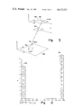
- FIG. 3 is a perspective view showing certain relationships useful for an understanding of the invention.
- FIG. 4 is a front view of a portion of the apparatus shown in FIG. 1, also showing certain relationships useful for a further understanding of the invention.
- FIG. 5 is a plan view of a workpiece illustrating certain relationships useful for understanding the invention.
- FIG. 6 is a plan view of a light pattern useful in the invention.
- FIG. 7 is a flow diagram illustrating practice of the invention.
- FIG. 7A is a perspective view of a portion of the apparatus of FIG. 1.
- FIG. 8 is a perspective view of a workpiece during practice of the invention.
- FIG. 9 is a plan view of patterns obtained in practice of the invention.
- FIG. 10 is a resulting image obtained with the patterns shown in FIG. 9.
- FIG. 11 is a more detailed flow diagram of a portion of the process of the flow diagram in FIG. 7.
- FIG. 12 is a plot of results obtained from the image of FIG. 10.
- FIG. 13 is a display output of results obtained from analysis in accordance with the invention of the image in FIG. 10.
- FIG. 14 is a perspective view of light patterns projected on another type of welding joint in practice of the invention.
- FIG. 15 is a plan view of an image obtained from the patterns in FIG. 14.
- FIG. 16 is a display output of results obtained from analysis in accordance with the invention of the image shown in FIG. 15.
- the apparatus includes an x-y table 10 driven by stepping motors 12 and 14.
- a workpiece 16 to be welded is positioned on the x-y table 10.
- a welding gun 18 of known type incorporating a welding wire feeder is mounted above the x-y table 10. In this embodiment, the workpiece 16 is thus moved to position it beneath the stationary welding gun 18.
- a third stepping motor 20 is connected to the welding gun 18 for pivoting the welding gun 18 about z axis 22.
- a manually operable rotary stage (not shown) is also provided to adjust the angle that welding gun 18 makes with respect to the plane of x-y table 10.
- a light source 24 is positioned above the x-y table 10 to illuminate the workpiece 16 to be welded with a light pattern 26. Further details on the nature of light pattern 26 are presented below in connection with the discussion of FIG. 6. Although the light source 24 can be implemented with any source that will project a pattern 26 having the characteristics discussed below on the workpiece 16, it is preferred to implement the light source 24 as a small, mechanically rugged projector head which receives a slide containing a suitable image for generation of the pattern 26. Such a projection head is desirably connected by a fiber optics bundle to an incandescent light source (not shown), remotely positioned from the welding gun 18 and x-y table 10 for reliability.
- a television camera 28 is positioned remote from the light source 24 to receive the light pattern 26, as reflected from the workpiece 16. It is important that the camera 28 be positioned remote from the light source 24, to give a different angle with respect to the workpiece 16, because the present invention utilizes triangulation, discussed more fully below, to determine three dimensional characteristics of workpiece 16 from a two dimensional image.
- a General Electric model TN 2500 CID solid state television camera is employed.
- Output 30 of the camera 28 is connected to camera interface circuits 32, which supply either a raw grey scale or a thresholded binary image on output 34 to a conventional television monitor 35, depending on a control input to the interface circuits 32 on line 37 from computer 38.
- the camera interface circuits 32 also have an output 36 as a direct memory access (DMA) input to computer 38. Further details on the camera interface circuits 32 are shown in FIG. 2, discussed below.
- Computer 38 may be essentially any commercially available minicomputer, implemented in the preferred embodiment with a PDP-11/34 minicomputer, available from Digital Equipment Corporation, Maynard, Mass.
- User access to the computer 38 is provided by means of a display terminal 40, such as a Tektronix 4006 display terminal, obtainable from Tektronix, Inc., Beaverton, Oreg.
- the display terminal 40 is connected to computer 38 by line 42.
- Computer 38 carries out analysis of data supplied by the camera interface circuits 32 on line 36, using a stored data analysis program, discussed below. Terminal 40 is used to display results of operations carried out on image data supplied to computer 38 on line 36 and to allow user access to computer 38.
- Line 44 is desirably implemented as a 1200-Baud, RS 232 type serial line.
- Controller 46 is connected to the stepping motors 12, 14 and 20 by lines 48, 50 and 52, respectively, to control positioning of the x-y table 10 and the welding gun 18.
- the controller 46 in a preferred embodiment, is implemented by a Summit Engineering model 8138 controller.
- Line 54 further connects the controller 46 to a welding power source 56, such as a Miller Electric model 330 ABT constant current welding power source, which is connected to the welding gun 18 by line 58.
- Bus 30 connects television camera 28 to a signal conditioning circuit 60.
- Signal conditioning circuit 60 performs the functions of level shifting, waveform shaping and isolation of the camera 28 from the remainder of the circuits in interface 32.
- Bus 62 supplies data from the signal conditioning circuit 60 to 1:2 demultiplexer circuit 64.
- Signal conditioning circuit 60 also supplies a timing signal to demultiplexer 64 via busses 66, 68 and 70.
- Busses 71 and 72 provide data from the demultiplexer 64 to memory 73.
- Memory control logic circuits 74 receive timing signals from signal conditioning circuit 60 on busses 66 and 75. Output 76 of the memory control logic 74 is connected to the memory 73.
- Output bus 77 from memory 73 is connected to 2:1 multiplexer 78, and via vus 79, to DMA input control circuit 80.
- DMA input control circuit 80 also receives a timing input via busses 66, 68 and 81 from signal conditioning circuit 60.
- Bus 36 supplies data from DMA input control circuit 80 to computer 38 (FIG. 1).
- Bus 36 also supplies data from computer 38 to DMA output control circuit 82.
- Busses 71 and 72 supply data from the DMA output control circuit 82 to memory 73.
- DMA output control circuit 82 receives timing signals from signal conditioning circuit 60 on busses 66, 68 and 83.
- a packed binary DMA input control circuit 84 is connected to DMA input control circuit 80 and DMA output control circuit 82 by busses 85 and 86. Busses 85, 86 and 37 also connect the DMA input control circuit 80, the DMA output control circuit 82, and the packed binary DMA input control circuit 84 to computer 38 for transmission of status and control signals.
- the packed binary DMA control circuit 84 is also connected to bus 36 by bus 87.
- a timing signal is supplied to packed binary DMA input control circuit 84 from signal conditioning circuit 60 via busses 66 and 68.
- Bus 89 also supplies these timing signals to multiplexer 78. Multiplexer 78 supplies data on busses 90 and 91 to video display control circuit 92 and comparator circuit 93, respectively.
- Video display control circuit 92 is a digital-to-analog (D/A) converter. Output 34 of the video display control circuit 92 supplies input signals to video monitor 35 (FIG. 1) via line 34.
- Comparator 93 receives a threshold input on bus 94 from manually settable or computer settable threshold circuit 95. If the data supplied on bus 91 is above the threshold on bus 94, comparator 93 provides an enable signal on lines 96 and 97 to packed DMA input control circuit 84 and video display control circuit 92.
- FIG. 3 is useful in understanding the process of extracting three-dimensional geometrical data from a two-dimensional image.
- an object plane 100 has a point 102 of coordinates x 1 , y 1 , z 1 , which is projected through pinhole 104 to give an image 106 in image plane 108, having coordinates u, v, w.
- the image 106 coordinates, u, v, w, of the point 102 with coordinates x 1 , y 1 , z 1 are ##EQU1## It should be noted that this transformation is ambiguous in that the point 110 having coordinates x 2 , y 2 , z 2 , also transforms into the same image point.
- Equation (1) If, however, in Equation (1), one of the coordinates is known, say x, it will then be possible to solve uniquely for y and z. What is needed, therefore, is a method of providing the value of one of the coordinates automatically, or some other linear constraint.
- FIG. 4 shows an elevation view of such an arrangement, in which light source 24 is displaced from camera 28 above workpiece 16. Taking the camera as the origin, the principal ray of the camera as the Z axis, and displacing the projector along the X-axis, we find that the equation of the principal ray of the projector is given by:
- ⁇ is the angle between the principal rays of the camera and the projector
- B the X intercept
- Equation (2) Inserting Equation (2) into Equation (1) and solving for x, y, and z in terms of the known quantities, u, v, ⁇ and B, we have: ##EQU2##
- This simple system may be used to measure the height of a single point on a plane.
- we may replace this single spot of light with a stripe, projected so as to be parallel with the y-axis.
- the elevation of each point on the stripe, and hence the rotation of the plane about the x-axis, may be determined by applying Equation (3) to each point in the stripe image.
- FIG. 6 shows such an array 120.
- the array 120 has stripes 122 equally spaced from one another.
- Reference stripes 124 have a different spacing between them than the spacing between stripes 122.
- the spacing between the reference stripes 124 is twice the spacing between the other stripes 122.
- the identity of any reflected image of a stripe 122 may then be determined unambiguously with respect to the reference stripes 124. This additional information allows the correspondence problem to be solved.
- the array 120 of light elements as shown in FIG. 6 may be used with apparatus as shown in FIG. 1 in a novel process for controlling the weld head 18 in FIG. 1.
- FIG. 7 is a flow diagram of such a process.
- weld geometry will be limited to straight fillet and lap welds on flat plates.
- the basic principles involved in the present apparatus and process can be demonstrated in a more straightforward manner.
- curved edges on flat planes to be welded can be reduced to a series of straight weld lines.
- this system can be extended by routine modification of the disclosed software to other workpieces, such as parts including curved surfaces and circular welds.
- the first two steps of camera calibration and projector calibration are performed off line when the system is initially set up to give a camera matrix, as indicated at 154, and light plane matrices, as indicated at 156.
- Camera calibration involves determination of a camera perspective transform, as well as scale factors, axis rotations, and translations necessary to convert from image coordinates in image plane 108 (FIG. 3) to the coordinate system of the x-y table, in object plane 100. This information constitutes output for use in the projector calibration as a single 4 ⁇ 4 homogeneous coordinate matrix.
- Projector calibration establishes the three-dimensional equations of each light plane in the structured light pattern. These equations are combined with the homogeneous camera transform obtained by the camera calibration step to yield a set of 4 ⁇ 3 matrices, one for each light plane, that are used to transform the image coordinates for a point on a particular line directly into its corresponding x-y-z location in space. Further mathematical details on homogeneous coordinates and the computation of the matrices in the camera calibration and projector calibration steps are described more completely below.
- Equation 1 To facilitate construction of parametric camera models and provide a more compact communication format for use with other system components (e.g., manipulators), it is convenient to represent the perspective transformation (Equation 1) and required axis rotation, translation, and scaling in homogeneous coordinates. This representation simplifies the computational mathematics involved in the transformation from image to "world” coordinates and also eliminates a problem of nonlinearity encountered in direct application of Equation 1.
- a point in three-dimensional space is represented in homogeneous coordinates as a four-element vector. If (x,y,z) are the coordinates of a point in three-dimensional space, the corresponding homogeneous representation is ##EQU3## Where S is a nonzero scale factor. Mapping a point from its homogeneous coordinates to the conventional three-dimensional form involves simply dividing by S.
- Equation 1 Any geometric transformation, such as translation, scaling, and rotation, is represented in homogeneous coordinates by a 4 ⁇ 4 matrix.
- Equation 1 the perspective transformation given by Equation 1 is represented in homogeneous coordinates as ##EQU4##
- Successive transformations of a single point may be concatenated by forming the product of the appropriate transformation matrices.
- P is the above perspective matrix
- R the rotation matrix
- the image coordinates, (u,v) of the point (x,y,z) obtained when the camera is rotated by an angle ⁇ about the z axis will be given by ##EQU6##
- This matrix product may be represented by a single matrix which is the product of all of the respective transformations.
- calibration is used with respect to the camera 28 (FIG. 1) to describe a technique for establishing a parametric model of the camera system. This model then enables measurements made in the coordinate system of the image to be related to a fixed, absolute world coordinate system. This capability is necessary for several reasons:
- Information concerning workpiece dimensions and details may be more easily encoded when referenced to an absolute coordinate system, rather than on a relative, point-by-point basis.
- the parametric model of the camera consists of a single 4 ⁇ 4 homogeneous coordinate matrix that combines camera perspective transformation, axis translations, and rotations necessary to transform measurements made on a camera image into the coordinate system of the x-y table.
- the linear constraint necessary to infer a three-dimensional structure from a two-dimensional image is determined during projector calibration by combining the camera model with the three-dimensional equations of the light planes.
- the result is a set of 4 ⁇ 3 matrices, one for each plane, that allow direct computation of the three-dimensional coordinates of any point in the camera's field of view from the corresponding image coordinates.
- the camera 28 is shown above x-y table 10 in FIG. 7A.
- the origin of the world coordinate system is taken to be the O,O point of the x-y table, as indicated at 160.
- the camera 28 is translated from this origin by an amount x c ,y c ,z c , panned about the y axis through an angle ⁇ , and tilted about the x axis through an amount ⁇ .
- the focal length of the camera lens is f
- This matrix has the property: ##EQU8## where x,y,z are the world coordinates for a point in space, and u,v are its corresponding image coordinates defined in the camera (Cx,Cy) system.
- the matrix C may be obtained by direct measurement of the angles ⁇ and ⁇ , the translation x c ,y c ,z c , and the known focal length of the lens. This procedure, however, is somewhat tedious and error-prone. This will be especially true if the camera is moved often (whether intentionally or otherwise), the internal camera geometry is unstable, or if the lens is less than optically perfect.
- the technique used here averts these problems, and renders the system almost "self-calibrating" by simply making a number of measurements on targets of known height that are placed on the x-y table and moved to a set of known locations.
- the camera matrix C is then computed by a simple least-squares fitting procedure described below. In this way most explicit measurements are eliminated (except, of course, the height of the target) and the various sources of error in the system (e.g., linear optical distortions, systematic lead screw errors, and camera tilt) treated as a lumped constant.
- the purpose of calibrating the projector is to derive the coefficients for the equations of each light plane. This is accomplished by obtaining images of the pattern as it is reflected from surfaces, at various known heights, placed parallel to the plane of the x-y table. In each image a set of x and y values for an arbitrary number of points along each light stripe 122 and 124 (FIG. 6) is computed and stored, using the known height z. When a sufficient number of images is obtained (e.g., three), these measured coordinates are used to derive, by the least-squares method, the coefficients for the three-dimensional equation for each light plane.
- a sufficient number of images e.g., three
- statistics are also computed, including the mean and variance of the spacing between the narrowly spaced stripes 122 as well as the ratio between the spacing of the reference stripes 124 and the narrowly spaced stripes 122. These data are output for use in locating the reference light stripes 124 in clustering, explained more fully below.
- the three-dimensional location of any arbitrary image point may be computed by means of the matrix equation: ##EQU11## where x,y,z are the world coordinates corresponding to the image point u,v,Cij are the indicated elements of the camera matrix, and A, B, C, and D are the coefficients from Equation 6 for the light plane upon which the point lies.
- this matrix may be inverted and the indicated multiplication performed symbolically.
- the equation may be recast into the form: ##EQU12## which may be solved in a manner similar to the camera transform.
- the matrices [Mij] are obtained by solving 12 rather messy equations involving A, B, C and D, and the Cij appearing in Equation 3. Although this is rather time-consuming during calibration, it need be done only once per bar, rather than once per measured point as in Equation 4.
- the output of the projector calibration procedure is this set of matrices, one matrix per light plane, along with the statistical parameters described above.
- FIG. 8 shows a fillet joint 164 formed by intersecting plates 166 and 168, positioned in welding jig 170.
- An array of narrowly spaced light stripes 122 and reference light stripes 124 is projected on the plates 166 and 168 from light source projector 24 (FIG. 1), to give the reflected image shown in FIG. 8.
- the resulting grey scale image viewed by camera 28 (FIG. 1) is supplied to computer 38 through camera interface circuits 32 and converted into run length coded binary form by a thresholding operation.
- the resulting binary image of fillet joint 164 is shown in FIG. 9.
- the same designations of 122 for the narrowly spaced light elements 122 and the reference light elements 124 is used in FIG. 9.
- the accuracy of weld geometry characterization obtained through use of the process of this invention depends on the spacing of the narrowly spaced light elements 122.
- a center-to-center spacing of about 0.25 inch (0.063 cm) and a spacing between the reference light elements of 0.5 inch (1.27 cm) has been found suitable to characterize weld geometry within an accuracy of 0.020 inch (0.051 cm).
- a closer spacing between the light elements 122 and 124 would be required.
- the initial processing of the binary image shown in FIG. 9 consists of a known form of connectivity analysis to extract the center line of each projected light element 122 or 124 in FIG. 9.
- the output of this initial processing is shown in FIG. 10 as a set of line segments 172, representing the center lines of the light elements 122 and 124, along with a set of line descriptors containing the initial and final image coordinates, the slope and x-intercept for each line segment 172 in the image of FIG. 10.
- the fillet joint data represented in part by FIG. 10 is now ready for clustering, indicated in FIG. 7 at 174.
- the plane surfaces comprising the joint 164 (FIG. 8) to be welded are reconstructed in the memory of computer 38 (FIG. 1) by grouping or "clustering" the line segments 172 (FIG. 10) obtained above according to various criteria.
- This clustering operation is designed to separate the image into its component planes and classify the line segments 172 belonging to each plane into discrete lists. This process consists of three steps:
- Step (3) Subdivision of surface height groups obtained in Step (2) according to their lateral position in the image.
- FIG. 11 A flow diagram of this processing is shown in FIG. 11. Operation of these different clustering processes is described below.
- Equation (3) it is seen that a change in height (z coordinate) of the workpiece results in a shift in the u value of the spot's image.
- the image will be a line.
- the slope of this line will range from 0 (parallel to the v-axis), when the workpiece is parallel to x-y plane, to approximately tan ⁇ as the workpiece is tilted towards a more vertical orientation.
- the line image will be broken into a number of straight line segments separated by discontinuous changes in slope. If several parallel lines are projected, all of the lines reflected from a given surface will have the same slope and the outline of the surface may be inferred from the locations of the slope discontinuities.
- slope clustering indicated at 176 in FIG. 11, to separate surfaces that have different orientations.
- This process may be described as a histogramming procedure in which line slopes are counted and each bin 178 (FIG. 12) of the histogram represents a narrow range of slope values.
- the slope of each line segment 172 (FIG. 10) in the image, computed during initial image processing, is examined and a line label (a pointer to the line descriptor in computer memory and represented by the circled numbers in FIG. 10) is deposited in the appropriate bin.
- the resulting distribution will have a peak corresponding to each different orientation. Thus, there are two peaks shown in FIG. 12, one for each bin 178.
- the lines reflected from it would be grouped with the part of the workpiece having the same orientation.
- the lines reflected from the workpiece are separated from those reflected from a background that has the same orientation, but differs in height.
- Separation of parallel, overlapping surfaces is done by means of line-spacing statistics obtained during projector calibration. For example, in the lap weld image shown in FIG. 15, a list ordered by ascending average u value comprises all line segments appearing in the image (u increases from bottom to top in FIG. 15). The separation in u between the first two elements 182 and 184 of the list is calculated and compared to the mean separation, within a specified number of standard deviations (currently about 2.5), measured when the projector was calibrated.
- the process is repeated between the first element and the next unexamined element of the list (e.g., first element 182 and third element 186, first element 182 and fourth element 188, etc.) until the trial value falls within the specified range.
- the first element 182 of the list is removed and used as the first element of a new list, which will contain all the lines for the given surface.
- the trial value is outside the tolerance range, it is compared to the spacing of the reference elements 190 and 192. If this comparison is within the specified bounds, the same action is taken; otherwise the loop proceeds. Iteration of this loop is continued, using the second element 184 of the two lines just compared as the initial (first) element.
- Line segments with the same average u value, and hence belonging to surfaces at the same height, are grouped together by this procedure. This situation is encountered, for example, in the square butt joint 112 shown in FIG. 5. Further decomposition is necessary to resolve this difficulty.
- This procedure is used to separate discrete workpieces that have the same orientation and height and is indicated at 194 in FIG. 11. It is used primarily to locate, for example, workpieces 116 and 118 comprising square butt joint 112 in FIG. 5.
- Zonal separation or clustering is also a histogram process--the histogram, in this case, being the distribution of the average v* values for all of the lines belonging to a set of surfaces having the same orientation and height.
- the value v* is computed by rotating the u-v coordinate system so as to minimize the total variance of the set of average v values for the line group being examined. In particular, if ⁇ is the computed angle of rotation, then:
- This rotated coordinate system is used to eliminate possible sources of error introduced by joint lines that run diagonally across the image.
- the reference elements 124 are first located by computing the ratio of the center-to-center spacing of each pair of elements 122 and 124 to the mean spacing of all the elements in the list. That pair of elements for which this ratio is greatest is taken to be the reference pair. This reference spacing ratio is also checked to be sure it is within the range encountered during calibration. If it is not, the image segment is rejected.
- the ratio of center-to-center distances is used here because this value is relatively unaffected by changes in the apparent width or spacing of the elements.
- apparent element width will change because the intensity of the light reflected into the camera from the marginally illuminated element edges will vary with the reflectivity of the surface.
- the absolute spacing of the elements will become smaller as the workpiece is moved closer to the camera.
- the x, y, and z coordinates for the endpoints of each element 122 and 124 are calculated by using the procedure described above. This step is indicated at 200 in FIG. 7.
- the output of this procedure is a plane descriptor block containing the average x, y, and z values (apparent centroid) for the surface of each workpiece e.g., 166 and 168 in FIG. 8, and lists containing the u, v, x, y, and z values for the endpoints of all line segments comprising the workpiece image. There are two such lists, one for points at the "top” (minimum v) of the image and the other for those at the bottom (maximum v).
- a parametric description of the joint geometry is obtained by fitting a mathematical surface to the data obtained from the previous step.
- the fitting step is indicated in FIG. 7 at 202.
- the surface used could be any analytic shape appropriate to the particular application.
- a comprehensive program for the apparatus of this invention would include subroutines for classifying the surfaces in order to select from appropriate formulas for further analysis of the workpiece in accordance with this invention. In pipe welding, for example, it would be appropriate to fit conic sections, such as an ellipse or circle. For very complex shapes other, higher-order curves might be used.
- This equation is fitted to the element endpoint data using the least squares method.
- the parameters A, B, C, and D are normalized so that A, B, and C are the direction cosines of the surface normal with respect to the x, y, and z axes, and D is the perpendicular distance from the origin to the plane surface. Note that the sign of D indicates on which side of the origin the plane lies.
- This step is indicated in FIG. 7 at 204.
- the surface descriptor blocks described above are organized into linked lists according to the relative position of each surface in the space. There are three such lists, arranged in ascending order according to the average x, y and z values respectively. Note that each surface appears once in each list. The relative position of a given surface is indicated by its position in each list.
- a simple fillet joint shown in FIG. 8, consists of two plates 166 and 168 that meet at an angle of, typically, 90 degrees. Defining the expected joint line to be approximately along the x axis, fillet joint 164 location proceeds in the following manner. The image is traversed in the y direction (perpendicular to the expected joint line) by stepping down the y-list. This list is searched exhaustively until a pair of adjacent planes is found whose surface normals form a 90-degree angle (plus or minus 2 degrees) in the y-z plane. A check is also made to verify that this intersection point is on the front side of the weld.
- results of this procedure 204 for the joint 164 in FIG. 8 are shown in FIG. 13 as they would be displayed on terminal 40 (FIG. 1).
- Line 206 identifies the joint 164.
- the displayed data of FIG. 13 includes an identification by means of arrow 208 of the first line 172 beyond line 206 in a proposed welding direction. The weld will terminate at the identified line to insure a complete weld of the joint 164.
- a typical lap joint 180 is shown in FIG. 14.
- the camera viewpoint in this case is directly above top plate 210, so that the vertical face (edge of the top plate) is not directly visible and the joint appears as a stacked assembly of two plates 210 and 212.
- the processed image of this joint is shown in FIG. 15.
- the lap joint 180 is located by finding the step height discontinuity between the two plates.
- the last (highest) element in the z-list is taken as the top plate 210.
- the next lower element in the list is then checked to confirm that its average z value differs from that of the first element by the known thickness of the top plate. If this test is successful, the edge list for the top plate, along with a flag indicating the location of the joint face with respect to the joint line 180, is then passed to the joint line fitting procedure. Note that in this case the joint width is taken to be zero.
- the joint path and fitup are defined by the workpiece edge data output by the locating procedures.
- a mathematical curve is fitted to these data to provide a parametric description of the three-dimensional trajectory. This is necessary for several reasons:
- the mathematical description obtained may be used as a basis for spatial interpolation in manipulator control.
- This model is necessary for splicing together joint path segments obtained from successive, overlapping images.
- This estimated trajectory is used as a baseline for measurement of joint width.
- This width information might be used, for example, to control torch weaving amplitude or to select alternative welding procedures, such as "stringering" to fill a wide joint.
- the edge point data are treated as the endpoints of run length segments, and the line indices are scan line serial numbers. These data are analyzed for connectivity and the straight line segments are fitted to the connected areas. The result of this procedure is shown as applied to the curved lap weld 180 (FIG. 14) in FIG. 16. Note that the curved joint line 180 has been broken into smaller straight line segments 210. In this case a continuum joint line is obtained by extrapolating each segment as indicated at 212 and joining them at their point of intersection 214.
- the procedure steps down the line, calculating the width of the joint at each edge point. These data along with the path segment endpoints, slope, and y intercept, are recorded in a list for use by the manipulator controller 46 (FIG. 1).
- the welding may now be carried out, as indicated at 216 in FIG. 7, to give a completed joint weld utilizing the results generated with the apparatus and process of this invention to generate appropriate control signals for controller 46 in FIG. 1.
- This apparatus and process is capable of characterizing three-dimensional welding joints and controlling the positioning of a welding head to carry out automatic welding of the joints on a real-time basis.
- the apparatus and process does not require the use of special configurations for different weld shapes. Because no sensor elements need to be placed near the workpiece being welded, the apparatus is suitable for use with a wide variety of weld shapes.
- the light source 24, camera 28 and welding gun 18 may be mounted on an arm of an, e.g., Cincinatti-Milacron T3 industrial robot, so that they move with respect to the workpiece 16, which may also either move as well or remain stationary. It is intended that such changes be included within the spirit and scope of the claims appended hereto.
Landscapes
- Engineering & Computer Science (AREA)
- Physics & Mathematics (AREA)
- Mechanical Engineering (AREA)
- General Physics & Mathematics (AREA)
- Optics & Photonics (AREA)
- Computer Vision & Pattern Recognition (AREA)
- Automation & Control Theory (AREA)
- Length Measuring Devices By Optical Means (AREA)
- Machine Tool Sensing Apparatuses (AREA)
- Electrical Discharge Machining, Electrochemical Machining, And Combined Machining (AREA)
- Perforating, Stamping-Out Or Severing By Means Other Than Cutting (AREA)
Priority Applications (9)
| Application Number | Priority Date | Filing Date | Title |
|---|---|---|---|
| US06/297,514 US4412121A (en) | 1981-08-28 | 1981-08-28 | Implement positioning apparatus and process |
| DE19823228014 DE3228014A1 (de) | 1981-08-28 | 1982-07-27 | Verfahren und einrichtung zur lagesteuerung eines werkzeugs relativ zu einem werkstueck |
| NO822589A NO822589L (no) | 1981-08-28 | 1982-07-28 | Fremgangsmaate og apparat for posisjonering av et verktoey eller instrument. |
| FR8213537A FR2511917A1 (fr) | 1981-08-28 | 1982-08-03 | Procede et appareil de commande du positionnement d'un outil par rapport a une piece |
| FI822967A FI822967A7 (fi) | 1981-08-28 | 1982-08-26 | Työvälineen asetuslaitteisto ja menetelmä asetuksen suorittamiseksi. |
| SE8204895A SE8204895L (sv) | 1981-08-28 | 1982-08-26 | Sett och anordning for placering av ett verktyg |
| GB08224623A GB2104652A (en) | 1981-08-28 | 1982-08-27 | Implement positioning control apparatus and processes |
| JP57147877A JPS5844972A (ja) | 1981-08-28 | 1982-08-27 | 器具の位置決め方法および装置 |
| DK385982A DK385982A (da) | 1981-08-28 | 1982-08-27 | Fremgangsmaade og apparat til positionering af et vaerktoej |
Applications Claiming Priority (1)
| Application Number | Priority Date | Filing Date | Title |
|---|---|---|---|
| US06/297,514 US4412121A (en) | 1981-08-28 | 1981-08-28 | Implement positioning apparatus and process |
Publications (1)
| Publication Number | Publication Date |
|---|---|
| US4412121A true US4412121A (en) | 1983-10-25 |
Family
ID=23146623
Family Applications (1)
| Application Number | Title | Priority Date | Filing Date |
|---|---|---|---|
| US06/297,514 Expired - Fee Related US4412121A (en) | 1981-08-28 | 1981-08-28 | Implement positioning apparatus and process |
Country Status (9)
| Country | Link |
|---|---|
| US (1) | US4412121A (da) |
| JP (1) | JPS5844972A (da) |
| DE (1) | DE3228014A1 (da) |
| DK (1) | DK385982A (da) |
| FI (1) | FI822967A7 (da) |
| FR (1) | FR2511917A1 (da) |
| GB (1) | GB2104652A (da) |
| NO (1) | NO822589L (da) |
| SE (1) | SE8204895L (da) |
Cited By (105)
| Publication number | Priority date | Publication date | Assignee | Title |
|---|---|---|---|---|
| US4493968A (en) * | 1983-07-13 | 1985-01-15 | Caterpillar Tractor Co. | Adaptive welder with laser TV-scanner |
| US4523287A (en) * | 1981-03-20 | 1985-06-11 | Hitachi, Ltd. | Method for extrapolating a path of a robot and apparatus therefor |
| US4532405A (en) * | 1983-11-23 | 1985-07-30 | General Electric Company | Arc welding torch with two integral optical systems |
| US4542279A (en) * | 1983-03-07 | 1985-09-17 | General Electric Company | Microvector control for edge and joint following |
| US4561333A (en) * | 1982-05-20 | 1985-12-31 | Agency Of Industrial Science & Technology | Diamond turning method for high-precision metal mirror |
| US4567348A (en) * | 1983-01-25 | 1986-01-28 | The United States Of America As Represented By The Administrator Of The National Aeronautics And Space Administration | Automated weld torch guidance control system |
| US4609939A (en) * | 1983-07-18 | 1986-09-02 | Toyota Jidosha Kabushiki Kaisha | Method of and apparatus for automatically correcting position of TV camera |
| US4611296A (en) * | 1983-11-11 | 1986-09-09 | Siemens Aktiengesellschaft | Manipulation device such as an industrial robot having at least one sensor |
| US4616121A (en) * | 1982-11-01 | 1986-10-07 | National Research Development Corporation | Automatic welding with imaging of workpiece surfaces and of the junction between the surfaces |
| US4658428A (en) * | 1985-07-17 | 1987-04-14 | Honeywell Inc. | Image recognition template generation |
| US4673795A (en) * | 1984-10-15 | 1987-06-16 | General Electric Company | Integrated robotic laser material processing and imaging system |
| US4761596A (en) * | 1985-06-01 | 1988-08-02 | Yaskawa Electric Mfg. Co., Ltd. | Method of detecting and controlling work start point of robot |
| US4788481A (en) * | 1986-03-10 | 1988-11-29 | Mitsubishi Denki Kabushiki Kaisha | Numerical control apparatus |
| US4812614A (en) * | 1987-02-26 | 1989-03-14 | Industrial Technology Research Institute | Machine vision seam tracking method and apparatus for welding robots |
| US4828159A (en) * | 1988-02-22 | 1989-05-09 | The Boeing Company | Automatic flush head fastener inspection device |
| US4837487A (en) * | 1984-02-22 | 1989-06-06 | Fanuc Ltd. | System for coupling a visual sensor processor and a robot controller |
| US4845556A (en) * | 1987-10-30 | 1989-07-04 | General Electric Company | Video spot detector |
| US4846576A (en) * | 1985-05-20 | 1989-07-11 | Fujitsu Limited | Method for measuring a three-dimensional position of an object |
| US4853771A (en) * | 1986-07-09 | 1989-08-01 | The United States Of America As Represented By The Secretary Of The Navy | Robotic vision system |
| EP0362421A1 (en) * | 1988-09-29 | 1990-04-11 | Nkk Corporation | Apparatus for automatically welding cylindrical vessel |
| US4965499A (en) * | 1987-12-31 | 1990-10-23 | Westinghouse Electric Corp | Parametric path modeling for an optical automatic seam tracker and real time robotic control system |
| DE4014808A1 (de) * | 1989-05-15 | 1990-11-22 | Gen Electric | Maschinensichtsystem |
| US4979815A (en) * | 1989-02-17 | 1990-12-25 | Tsikos Constantine J | Laser range imaging system based on projective geometry |
| US4991224A (en) * | 1986-09-03 | 1991-02-05 | Kabushiki Kaisha Toshiba | Apparatus and method for labeling connected component in a three-dimensional image |
| US4995087A (en) * | 1989-05-15 | 1991-02-19 | General Electric Company | Machine vision system |
| US5001324A (en) * | 1989-09-14 | 1991-03-19 | General Electric Company | Precision joint tracking laser welding system |
| US5068588A (en) * | 1988-12-20 | 1991-11-26 | Matsushita Electric Industrial Co., Ltd. | Apparatus for mounting a flat package type ic |
| US5375175A (en) * | 1992-03-06 | 1994-12-20 | The Board Of Trustees Of The Leland Stanford Junior University | Method and apparatus of measuring line structures with an optical microscope by data clustering and classification |
| US5528194A (en) * | 1991-05-13 | 1996-06-18 | Sony Corporation | Apparatus and method for performing geometric transformations on an input image |
| US5602967A (en) * | 1981-05-11 | 1997-02-11 | Sensor Adaptive Machines, Inc. | Vision target based assembly |
| US5608847A (en) * | 1981-05-11 | 1997-03-04 | Sensor Adaptive Machines, Inc. | Vision target based assembly |
| US5671053A (en) * | 1995-11-16 | 1997-09-23 | Virtek Vision Corp. | Method of calibrating laser projector using moving reflector |
| US5813819A (en) * | 1992-06-05 | 1998-09-29 | Tokyo Electron Limited | Substrate transfer apparatus, and method of transferring substrates |
| US5818595A (en) * | 1994-10-11 | 1998-10-06 | Komatsu Ltd. | Work piece butt position detecting method for butt welding |
| US6000598A (en) * | 1996-11-13 | 1999-12-14 | Samsung Electronics Co., Ltd. | Method for correcting the direction of weaving of a welding torch with respect to a welding centerline |
| US6101455A (en) * | 1998-05-14 | 2000-08-08 | Davis; Michael S. | Automatic calibration of cameras and structured light sources |
| US6163946A (en) * | 1981-05-11 | 2000-12-26 | Great Lakes Intellectual Property | Vision target based assembly |
| US6167607B1 (en) * | 1981-05-11 | 2001-01-02 | Great Lakes Intellectual Property | Vision target based assembly |
| US6191812B1 (en) * | 1997-04-01 | 2001-02-20 | Rt-Set Ltd. | Method of providing background patterns for camera tracking |
| US6385335B1 (en) * | 1996-02-27 | 2002-05-07 | Cyberoptics Corp. | Apparatus and method for estimating background tilt and offset |
| CN1086162C (zh) * | 1997-05-13 | 2002-06-12 | 三星电子株式会社 | 机器人的初始焊接位置检测方法 |
| US6453213B1 (en) * | 2000-12-06 | 2002-09-17 | Samsung Electronics Co., Ltd. | Robot control system and method |
| RU2220474C1 (ru) * | 2002-11-27 | 2003-12-27 | Открытое акционерное общество "Экспериментальный научно-исследовательский институт металлорежущих станков" | Способ позиционирования пластин из полупроводниковых материалов в координатной системе отсчета установки для абразивной резки пластин на "чип"ы |
| US20040013295A1 (en) * | 2002-03-15 | 2004-01-22 | Kohtaro Sabe | Obstacle recognition apparatus and method, obstacle recognition program, and mobile robot apparatus |
| US20040105519A1 (en) * | 1999-03-16 | 2004-06-03 | Yuji Yamada | Manufacturing method and device of control rods for nuclear reactors |
| US20050088643A1 (en) * | 2003-09-15 | 2005-04-28 | Anderson Noel W. | Method and system for identifying an edge of a crop |
| US20060067830A1 (en) * | 2004-09-29 | 2006-03-30 | Wen Guo | Method to restore an airfoil leading edge |
| WO2007029038A1 (en) * | 2005-09-05 | 2007-03-15 | Sld Limited | Laser imaging apparatus and method |
| US20080319557A1 (en) * | 2005-07-06 | 2008-12-25 | Airbus Uk Limited | Program-Controlled Process |
| US20090103112A1 (en) * | 2007-10-23 | 2009-04-23 | Gii Acquisition, Llc Dba General Inspection, Llc | Non-Contact Method And System For Inspecting Parts |
| US20090240372A1 (en) * | 2008-03-21 | 2009-09-24 | Variation Reduction Solutions, Inc. | External system for robotic accuracy enhancement |
| CN102513708A (zh) * | 2011-11-25 | 2012-06-27 | 湖南大学 | 主动式短波长激光焊接小孔监测及焊缝跟踪集成装置 |
| US20140007634A1 (en) * | 2009-10-19 | 2014-01-09 | Yoshito Isei | Method for measuring sheet material flatness and method for producing steel sheet using said measuring method |
| US8704890B2 (en) * | 2010-08-19 | 2014-04-22 | Olympus Corporation | Inspection apparatus and measuring method |
| US20150194073A1 (en) * | 2014-01-07 | 2015-07-09 | Illinois Tool Works Inc. | Welding software for detection and control of devices and for analysis of data |
| JP2015194477A (ja) * | 2014-03-20 | 2015-11-05 | キヤノン株式会社 | 情報処理装置、情報処理方法及びプログラム |
| US20160291569A1 (en) * | 2011-05-19 | 2016-10-06 | Shaper Tools, Inc. | Automatically guided tools |
| US9583023B2 (en) | 2013-03-15 | 2017-02-28 | Illinois Tool Works Inc. | Welding torch for a welding training system |
| US9583014B2 (en) | 2012-11-09 | 2017-02-28 | Illinois Tool Works Inc. | System and device for welding training |
| US9666100B2 (en) | 2013-03-15 | 2017-05-30 | Illinois Tool Works Inc. | Calibration devices for a welding training system |
| US9672757B2 (en) | 2013-03-15 | 2017-06-06 | Illinois Tool Works Inc. | Multi-mode software and method for a welding training system |
| US9713852B2 (en) | 2013-03-15 | 2017-07-25 | Illinois Tool Works Inc. | Welding training systems and devices |
| US9728103B2 (en) | 2013-03-15 | 2017-08-08 | Illinois Tool Works Inc. | Data storage and analysis for a welding training system |
| US9724788B2 (en) | 2014-01-07 | 2017-08-08 | Illinois Tool Works Inc. | Electrical assemblies for a welding system |
| US9724787B2 (en) | 2014-08-07 | 2017-08-08 | Illinois Tool Works Inc. | System and method of monitoring a welding environment |
| US9751149B2 (en) | 2014-01-07 | 2017-09-05 | Illinois Tool Works Inc. | Welding stand for a welding system |
| US9757819B2 (en) | 2014-01-07 | 2017-09-12 | Illinois Tool Works Inc. | Calibration tool and method for a welding system |
| US9862049B2 (en) | 2014-06-27 | 2018-01-09 | Illinois Tool Works Inc. | System and method of welding system operator identification |
| US9875665B2 (en) | 2014-08-18 | 2018-01-23 | Illinois Tool Works Inc. | Weld training system and method |
| US9937578B2 (en) | 2014-06-27 | 2018-04-10 | Illinois Tool Works Inc. | System and method for remote welding training |
| US10056010B2 (en) | 2013-12-03 | 2018-08-21 | Illinois Tool Works Inc. | Systems and methods for a weld training system |
| CN108568624A (zh) * | 2018-03-29 | 2018-09-25 | 东风贝洱热系统有限公司 | 一种基于图像处理的机械臂焊接系统及焊接方法 |
| US10096268B2 (en) | 2011-08-10 | 2018-10-09 | Illinois Tool Works Inc. | System and device for welding training |
| US10105782B2 (en) | 2014-01-07 | 2018-10-23 | Illinois Tool Works Inc. | Feedback from a welding torch of a welding system |
| US10170019B2 (en) | 2014-01-07 | 2019-01-01 | Illinois Tool Works Inc. | Feedback from a welding torch of a welding system |
| US10204406B2 (en) | 2014-11-05 | 2019-02-12 | Illinois Tool Works Inc. | System and method of controlling welding system camera exposure and marker illumination |
| US10210773B2 (en) | 2014-11-05 | 2019-02-19 | Illinois Tool Works Inc. | System and method for welding torch display |
| US10239147B2 (en) | 2014-10-16 | 2019-03-26 | Illinois Tool Works Inc. | Sensor-based power controls for a welding system |
| US10307853B2 (en) | 2014-06-27 | 2019-06-04 | Illinois Tool Works Inc. | System and method for managing welding data |
| US10332271B2 (en) * | 2017-03-14 | 2019-06-25 | Tsinghua University | Apparatus and method for detecting multilayer multipass welding trajectory |
| US10373304B2 (en) | 2014-11-05 | 2019-08-06 | Illinois Tool Works Inc. | System and method of arranging welding device markers |
| US10373517B2 (en) | 2015-08-12 | 2019-08-06 | Illinois Tool Works Inc. | Simulation stick welding electrode holder systems and methods |
| US10402959B2 (en) | 2014-11-05 | 2019-09-03 | Illinois Tool Works Inc. | System and method of active torch marker control |
| US10417934B2 (en) | 2014-11-05 | 2019-09-17 | Illinois Tool Works Inc. | System and method of reviewing weld data |
| US10427239B2 (en) | 2015-04-02 | 2019-10-01 | Illinois Tool Works Inc. | Systems and methods for tracking weld training arc parameters |
| US10438505B2 (en) | 2015-08-12 | 2019-10-08 | Illinois Tool Works | Welding training system interface |
| US10490098B2 (en) | 2014-11-05 | 2019-11-26 | Illinois Tool Works Inc. | System and method of recording multi-run data |
| US10551179B2 (en) | 2018-04-30 | 2020-02-04 | Path Robotics, Inc. | Reflection refuting laser scanner |
| US10593230B2 (en) | 2015-08-12 | 2020-03-17 | Illinois Tool Works Inc. | Stick welding electrode holder systems and methods |
| US10657839B2 (en) | 2015-08-12 | 2020-05-19 | Illinois Tool Works Inc. | Stick welding electrode holders with real-time feedback features |
| US10665128B2 (en) | 2014-06-27 | 2020-05-26 | Illinois Tool Works Inc. | System and method of monitoring welding information |
| US10748442B2 (en) | 2008-05-28 | 2020-08-18 | Illinois Tool Works Inc. | Welding training system |
| US11014183B2 (en) | 2014-08-07 | 2021-05-25 | Illinois Tool Works Inc. | System and method of marking a welding workpiece |
| US11247289B2 (en) | 2014-10-16 | 2022-02-15 | Illinois Tool Works Inc. | Remote power supply parameter adjustment |
| US11267153B2 (en) | 2012-04-26 | 2022-03-08 | Shaper Tools, Inc. | Systems and methods for performing a task on a material, or locating the position of a device relative to the surface of the material |
| US11288978B2 (en) | 2019-07-22 | 2022-03-29 | Illinois Tool Works Inc. | Gas tungsten arc welding training systems |
| US11511382B2 (en) | 2015-05-13 | 2022-11-29 | Shaper Tools, Inc. | Systems, methods and apparatus for guided tools |
| US11537099B2 (en) | 2016-08-19 | 2022-12-27 | Sharper Tools, Inc. | Systems, methods and apparatus for sharing tool fabrication and design data |
| US11548162B2 (en) | 2021-02-24 | 2023-01-10 | Path Robotics, Inc. | Autonomous welding robots |
| US11759952B2 (en) | 2020-07-17 | 2023-09-19 | Path Robotics, Inc. | Real time feedback and dynamic adjustment for welding robots |
| US11776423B2 (en) | 2019-07-22 | 2023-10-03 | Illinois Tool Works Inc. | Connection boxes for gas tungsten arc welding training systems |
| US12277369B2 (en) | 2021-10-18 | 2025-04-15 | Path Robotics, Inc. | Generating simulated weld paths for a welding robot |
| US12358138B2 (en) | 2021-11-19 | 2025-07-15 | Path Robotics, Inc. | Machine learning logic-based adjustment techniques for robots |
| US12508665B2 (en) | 2022-04-19 | 2025-12-30 | Path Robotics, Inc. | Autonomous assembly robots |
| US12521884B2 (en) | 2022-07-26 | 2026-01-13 | Path Robotics, Inc. | Techniques for multipass welding |
Families Citing this family (17)
| Publication number | Priority date | Publication date | Assignee | Title |
|---|---|---|---|---|
| JPS61152382A (ja) * | 1984-12-27 | 1986-07-11 | 三井造船株式会社 | 溶接ロボツトの制御方法 |
| WO1986004847A1 (en) * | 1985-02-23 | 1986-08-28 | N.I.S. Engineering Limited | Laser apparatus |
| DE3579812D1 (de) * | 1985-02-25 | 1990-10-25 | Caterpillar Inc | Adaptive schweissvorrichtung mit korrectur der fuellungssteuerung fuer gekruemmte schweissrinnen. |
| JPS61203285A (ja) * | 1985-03-04 | 1986-09-09 | 株式会社日立製作所 | ロボツトの動作制御方法 |
| FR2605401B1 (fr) * | 1986-10-20 | 1992-04-17 | France Etat Armement | Procede et dispositif optoelectronique de mesure en temps reel de mouvements d'une structure solide soumise a l'effet d'un fluide |
| FR2606871B1 (fr) * | 1986-11-13 | 1990-11-09 | Imajesa | Dispositif de reconnaissance d'objets disposes sur un plan, et systeme de depalettisation mettant en oeuvre un tel dispositif |
| JP2548027B2 (ja) * | 1988-06-30 | 1996-10-30 | ファナック株式会社 | アークビジョンセンサ操作方式 |
| FR2670283B1 (fr) * | 1990-12-05 | 1994-10-14 | Commissariat Energie Atomique | Procede d'etalonnage d'un systeme de metrologie tridimensionnelle. |
| DE4336730A1 (de) * | 1993-10-28 | 1995-05-04 | Marquardt Gmbh | Elektrowerkzeug |
| GB9323054D0 (en) * | 1993-11-09 | 1994-01-05 | British Nuclear Fuels Plc | Determination of the surface properties of an omject |
| RU2165348C1 (ru) * | 1999-08-20 | 2001-04-20 | Открытое акционерное общество "Экспериментальный научно-исследовательский институт металлорежущих станков" | Способ позиционирования инструмента в координатной системе отсчета станка |
| GB9923795D0 (en) | 1999-10-09 | 1999-12-08 | British Aerospace | Micropositioning system |
| AU2001281761A1 (en) * | 2000-08-25 | 2002-03-04 | 3Shape Aps | Method and apparatus for three-dimensional optical scanning of interior surfaces |
| US7625335B2 (en) | 2000-08-25 | 2009-12-01 | 3Shape Aps | Method and apparatus for three-dimensional optical scanning of interior surfaces |
| ES2378060T3 (es) | 2001-03-02 | 2012-04-04 | 3Shape A/S | Procedimiento para modelar piezas auriculares personalizadas |
| RU2279964C1 (ru) * | 2005-05-27 | 2006-07-20 | Научно-исследовательский институт Гознака | Способ позиционирования инструмента в координатной системе отсчета станка автоматизированного гравировального комплекса |
| RU2721571C9 (ru) * | 2019-07-09 | 2020-08-05 | Дмитрий Владимирович Клепиков | Способ формирования субъективной трехмерной пространственной звуковой картины для пользователя через наушники |
Citations (4)
| Publication number | Priority date | Publication date | Assignee | Title |
|---|---|---|---|---|
| DE2500182A1 (de) * | 1975-01-03 | 1976-07-08 | Fraunhofer Ges Fuer Foerderung | Verfahren zur optischen ermittlung und optischen messung der signifikanten merkmale aus dem bild der schweisstelle beim lichtbogen-schutzgasschweissen und deren umsetzung in einer regeleinrichtung zur regelung des schweissprozesses |
| DE2711660A1 (de) * | 1977-03-17 | 1978-09-21 | Fraunhofer Ges Forschung | Optische sensoren fuer schweissbahnverfolgung mit lichtschnittbildern |
| JPS5550984A (en) * | 1978-10-05 | 1980-04-14 | Hitachi Zosen Corp | Controlling method for groove tracing |
| US4212073A (en) * | 1978-12-13 | 1980-07-08 | Balasubramanian N | Method and system for surface contouring |
-
1981
- 1981-08-28 US US06/297,514 patent/US4412121A/en not_active Expired - Fee Related
-
1982
- 1982-07-27 DE DE19823228014 patent/DE3228014A1/de not_active Withdrawn
- 1982-07-28 NO NO822589A patent/NO822589L/no unknown
- 1982-08-03 FR FR8213537A patent/FR2511917A1/fr not_active Withdrawn
- 1982-08-26 SE SE8204895A patent/SE8204895L/ not_active Application Discontinuation
- 1982-08-26 FI FI822967A patent/FI822967A7/fi not_active Application Discontinuation
- 1982-08-27 GB GB08224623A patent/GB2104652A/en not_active Withdrawn
- 1982-08-27 DK DK385982A patent/DK385982A/da not_active Application Discontinuation
- 1982-08-27 JP JP57147877A patent/JPS5844972A/ja active Pending
Patent Citations (4)
| Publication number | Priority date | Publication date | Assignee | Title |
|---|---|---|---|---|
| DE2500182A1 (de) * | 1975-01-03 | 1976-07-08 | Fraunhofer Ges Fuer Foerderung | Verfahren zur optischen ermittlung und optischen messung der signifikanten merkmale aus dem bild der schweisstelle beim lichtbogen-schutzgasschweissen und deren umsetzung in einer regeleinrichtung zur regelung des schweissprozesses |
| DE2711660A1 (de) * | 1977-03-17 | 1978-09-21 | Fraunhofer Ges Forschung | Optische sensoren fuer schweissbahnverfolgung mit lichtschnittbildern |
| JPS5550984A (en) * | 1978-10-05 | 1980-04-14 | Hitachi Zosen Corp | Controlling method for groove tracing |
| US4212073A (en) * | 1978-12-13 | 1980-07-08 | Balasubramanian N | Method and system for surface contouring |
Cited By (150)
| Publication number | Priority date | Publication date | Assignee | Title |
|---|---|---|---|---|
| US4523287A (en) * | 1981-03-20 | 1985-06-11 | Hitachi, Ltd. | Method for extrapolating a path of a robot and apparatus therefor |
| US6314631B1 (en) * | 1981-05-11 | 2001-11-13 | Great Lakes Intellectual Property | Vision target based assembly |
| US6301763B1 (en) * | 1981-05-11 | 2001-10-16 | Great Lakes Intellectual Property Ltd. | Determining position or orientation of object in three dimensions |
| US5608847A (en) * | 1981-05-11 | 1997-03-04 | Sensor Adaptive Machines, Inc. | Vision target based assembly |
| US6163946A (en) * | 1981-05-11 | 2000-12-26 | Great Lakes Intellectual Property | Vision target based assembly |
| US5602967A (en) * | 1981-05-11 | 1997-02-11 | Sensor Adaptive Machines, Inc. | Vision target based assembly |
| US6167607B1 (en) * | 1981-05-11 | 2001-01-02 | Great Lakes Intellectual Property | Vision target based assembly |
| US6317953B1 (en) * | 1981-05-11 | 2001-11-20 | Lmi-Diffracto | Vision target based assembly |
| US4561333A (en) * | 1982-05-20 | 1985-12-31 | Agency Of Industrial Science & Technology | Diamond turning method for high-precision metal mirror |
| US4616121A (en) * | 1982-11-01 | 1986-10-07 | National Research Development Corporation | Automatic welding with imaging of workpiece surfaces and of the junction between the surfaces |
| US4567348A (en) * | 1983-01-25 | 1986-01-28 | The United States Of America As Represented By The Administrator Of The National Aeronautics And Space Administration | Automated weld torch guidance control system |
| US4542279A (en) * | 1983-03-07 | 1985-09-17 | General Electric Company | Microvector control for edge and joint following |
| US4493968A (en) * | 1983-07-13 | 1985-01-15 | Caterpillar Tractor Co. | Adaptive welder with laser TV-scanner |
| US4609939A (en) * | 1983-07-18 | 1986-09-02 | Toyota Jidosha Kabushiki Kaisha | Method of and apparatus for automatically correcting position of TV camera |
| US4611296A (en) * | 1983-11-11 | 1986-09-09 | Siemens Aktiengesellschaft | Manipulation device such as an industrial robot having at least one sensor |
| US4532405A (en) * | 1983-11-23 | 1985-07-30 | General Electric Company | Arc welding torch with two integral optical systems |
| US4837487A (en) * | 1984-02-22 | 1989-06-06 | Fanuc Ltd. | System for coupling a visual sensor processor and a robot controller |
| US4673795A (en) * | 1984-10-15 | 1987-06-16 | General Electric Company | Integrated robotic laser material processing and imaging system |
| US4846576A (en) * | 1985-05-20 | 1989-07-11 | Fujitsu Limited | Method for measuring a three-dimensional position of an object |
| US4761596A (en) * | 1985-06-01 | 1988-08-02 | Yaskawa Electric Mfg. Co., Ltd. | Method of detecting and controlling work start point of robot |
| US4658428A (en) * | 1985-07-17 | 1987-04-14 | Honeywell Inc. | Image recognition template generation |
| US4788481A (en) * | 1986-03-10 | 1988-11-29 | Mitsubishi Denki Kabushiki Kaisha | Numerical control apparatus |
| US4853771A (en) * | 1986-07-09 | 1989-08-01 | The United States Of America As Represented By The Secretary Of The Navy | Robotic vision system |
| US4991224A (en) * | 1986-09-03 | 1991-02-05 | Kabushiki Kaisha Toshiba | Apparatus and method for labeling connected component in a three-dimensional image |
| US4812614A (en) * | 1987-02-26 | 1989-03-14 | Industrial Technology Research Institute | Machine vision seam tracking method and apparatus for welding robots |
| US4845556A (en) * | 1987-10-30 | 1989-07-04 | General Electric Company | Video spot detector |
| US4965499A (en) * | 1987-12-31 | 1990-10-23 | Westinghouse Electric Corp | Parametric path modeling for an optical automatic seam tracker and real time robotic control system |
| US4828159A (en) * | 1988-02-22 | 1989-05-09 | The Boeing Company | Automatic flush head fastener inspection device |
| EP0362421A1 (en) * | 1988-09-29 | 1990-04-11 | Nkk Corporation | Apparatus for automatically welding cylindrical vessel |
| US5068588A (en) * | 1988-12-20 | 1991-11-26 | Matsushita Electric Industrial Co., Ltd. | Apparatus for mounting a flat package type ic |
| US4979815A (en) * | 1989-02-17 | 1990-12-25 | Tsikos Constantine J | Laser range imaging system based on projective geometry |
| US4998005A (en) * | 1989-05-15 | 1991-03-05 | General Electric Company | Machine vision system |
| DE4014808A1 (de) * | 1989-05-15 | 1990-11-22 | Gen Electric | Maschinensichtsystem |
| US4995087A (en) * | 1989-05-15 | 1991-02-19 | General Electric Company | Machine vision system |
| US5001324A (en) * | 1989-09-14 | 1991-03-19 | General Electric Company | Precision joint tracking laser welding system |
| US5528194A (en) * | 1991-05-13 | 1996-06-18 | Sony Corporation | Apparatus and method for performing geometric transformations on an input image |
| US5375175A (en) * | 1992-03-06 | 1994-12-20 | The Board Of Trustees Of The Leland Stanford Junior University | Method and apparatus of measuring line structures with an optical microscope by data clustering and classification |
| US5813819A (en) * | 1992-06-05 | 1998-09-29 | Tokyo Electron Limited | Substrate transfer apparatus, and method of transferring substrates |
| US5818595A (en) * | 1994-10-11 | 1998-10-06 | Komatsu Ltd. | Work piece butt position detecting method for butt welding |
| US5671053A (en) * | 1995-11-16 | 1997-09-23 | Virtek Vision Corp. | Method of calibrating laser projector using moving reflector |
| US6385335B1 (en) * | 1996-02-27 | 2002-05-07 | Cyberoptics Corp. | Apparatus and method for estimating background tilt and offset |
| US6000598A (en) * | 1996-11-13 | 1999-12-14 | Samsung Electronics Co., Ltd. | Method for correcting the direction of weaving of a welding torch with respect to a welding centerline |
| US6191812B1 (en) * | 1997-04-01 | 2001-02-20 | Rt-Set Ltd. | Method of providing background patterns for camera tracking |
| CN1086162C (zh) * | 1997-05-13 | 2002-06-12 | 三星电子株式会社 | 机器人的初始焊接位置检测方法 |
| US6101455A (en) * | 1998-05-14 | 2000-08-08 | Davis; Michael S. | Automatic calibration of cameras and structured light sources |
| US20040105519A1 (en) * | 1999-03-16 | 2004-06-03 | Yuji Yamada | Manufacturing method and device of control rods for nuclear reactors |
| US6453213B1 (en) * | 2000-12-06 | 2002-09-17 | Samsung Electronics Co., Ltd. | Robot control system and method |
| US7386163B2 (en) * | 2002-03-15 | 2008-06-10 | Sony Corporation | Obstacle recognition apparatus and method, obstacle recognition program, and mobile robot apparatus |
| US20040013295A1 (en) * | 2002-03-15 | 2004-01-22 | Kohtaro Sabe | Obstacle recognition apparatus and method, obstacle recognition program, and mobile robot apparatus |
| RU2220474C1 (ru) * | 2002-11-27 | 2003-12-27 | Открытое акционерное общество "Экспериментальный научно-исследовательский институт металлорежущих станков" | Способ позиционирования пластин из полупроводниковых материалов в координатной системе отсчета установки для абразивной резки пластин на "чип"ы |
| US20050088643A1 (en) * | 2003-09-15 | 2005-04-28 | Anderson Noel W. | Method and system for identifying an edge of a crop |
| US7916898B2 (en) * | 2003-09-15 | 2011-03-29 | Deere & Company | Method and system for identifying an edge of a crop |
| US20060067830A1 (en) * | 2004-09-29 | 2006-03-30 | Wen Guo | Method to restore an airfoil leading edge |
| US7813830B2 (en) * | 2005-07-06 | 2010-10-12 | Airbus Uk Limited | Method and an apparatus for performing a program controlled process on a component |
| US20080319557A1 (en) * | 2005-07-06 | 2008-12-25 | Airbus Uk Limited | Program-Controlled Process |
| USRE45391E1 (en) * | 2005-07-06 | 2015-02-24 | Airbus Operations Limited | Method and an apparatus for performing a program controlled process on a component |
| WO2007029038A1 (en) * | 2005-09-05 | 2007-03-15 | Sld Limited | Laser imaging apparatus and method |
| US20090103112A1 (en) * | 2007-10-23 | 2009-04-23 | Gii Acquisition, Llc Dba General Inspection, Llc | Non-Contact Method And System For Inspecting Parts |
| US7920278B2 (en) * | 2007-10-23 | 2011-04-05 | Gii Acquisition, Llc | Non-contact method and system for inspecting parts |
| US8509949B2 (en) | 2008-03-21 | 2013-08-13 | Variation Reduction Solutions, Inc. | External system for robotic accuracy enhancement |
| US20090240372A1 (en) * | 2008-03-21 | 2009-09-24 | Variation Reduction Solutions, Inc. | External system for robotic accuracy enhancement |
| US10748442B2 (en) | 2008-05-28 | 2020-08-18 | Illinois Tool Works Inc. | Welding training system |
| US11423800B2 (en) | 2008-05-28 | 2022-08-23 | Illinois Tool Works Inc. | Welding training system |
| US11749133B2 (en) | 2008-05-28 | 2023-09-05 | Illinois Tool Works Inc. | Welding training system |
| US20140007634A1 (en) * | 2009-10-19 | 2014-01-09 | Yoshito Isei | Method for measuring sheet material flatness and method for producing steel sheet using said measuring method |
| US9138790B2 (en) * | 2009-10-19 | 2015-09-22 | Nippon Steel & Sumitomo Metal Corporation | Method for measuring sheet material flatness and method for producing steel sheet using said measuring method |
| US8704890B2 (en) * | 2010-08-19 | 2014-04-22 | Olympus Corporation | Inspection apparatus and measuring method |
| US20160291569A1 (en) * | 2011-05-19 | 2016-10-06 | Shaper Tools, Inc. | Automatically guided tools |
| US10795333B2 (en) | 2011-05-19 | 2020-10-06 | Shaper Tools, Inc. | Automatically guided tools |
| US10788804B2 (en) * | 2011-05-19 | 2020-09-29 | Shaper Tools, Inc. | Automatically guided tools |
| US10096268B2 (en) | 2011-08-10 | 2018-10-09 | Illinois Tool Works Inc. | System and device for welding training |
| CN102513708B (zh) * | 2011-11-25 | 2015-01-07 | 湖南大学 | 主动式短波长激光焊接小孔监测及焊缝跟踪集成装置 |
| CN102513708A (zh) * | 2011-11-25 | 2012-06-27 | 湖南大学 | 主动式短波长激光焊接小孔监测及焊缝跟踪集成装置 |
| US11267153B2 (en) | 2012-04-26 | 2022-03-08 | Shaper Tools, Inc. | Systems and methods for performing a task on a material, or locating the position of a device relative to the surface of the material |
| US9583014B2 (en) | 2012-11-09 | 2017-02-28 | Illinois Tool Works Inc. | System and device for welding training |
| US10417935B2 (en) | 2012-11-09 | 2019-09-17 | Illinois Tool Works Inc. | System and device for welding training |
| US9713852B2 (en) | 2013-03-15 | 2017-07-25 | Illinois Tool Works Inc. | Welding training systems and devices |
| US9583023B2 (en) | 2013-03-15 | 2017-02-28 | Illinois Tool Works Inc. | Welding torch for a welding training system |
| US9672757B2 (en) | 2013-03-15 | 2017-06-06 | Illinois Tool Works Inc. | Multi-mode software and method for a welding training system |
| US10482788B2 (en) | 2013-03-15 | 2019-11-19 | Illinois Tool Works Inc. | Welding torch for a welding training system |
| US9666100B2 (en) | 2013-03-15 | 2017-05-30 | Illinois Tool Works Inc. | Calibration devices for a welding training system |
| US9728103B2 (en) | 2013-03-15 | 2017-08-08 | Illinois Tool Works Inc. | Data storage and analysis for a welding training system |
| US11127313B2 (en) | 2013-12-03 | 2021-09-21 | Illinois Tool Works Inc. | Systems and methods for a weld training system |
| US10056010B2 (en) | 2013-12-03 | 2018-08-21 | Illinois Tool Works Inc. | Systems and methods for a weld training system |
| US10913126B2 (en) | 2014-01-07 | 2021-02-09 | Illinois Tool Works Inc. | Welding software for detection and control of devices and for analysis of data |
| US9589481B2 (en) * | 2014-01-07 | 2017-03-07 | Illinois Tool Works Inc. | Welding software for detection and control of devices and for analysis of data |
| US10105782B2 (en) | 2014-01-07 | 2018-10-23 | Illinois Tool Works Inc. | Feedback from a welding torch of a welding system |
| US10170019B2 (en) | 2014-01-07 | 2019-01-01 | Illinois Tool Works Inc. | Feedback from a welding torch of a welding system |
| US11676509B2 (en) | 2014-01-07 | 2023-06-13 | Illinois Tool Works Inc. | Feedback from a welding torch of a welding system |
| US20150194073A1 (en) * | 2014-01-07 | 2015-07-09 | Illinois Tool Works Inc. | Welding software for detection and control of devices and for analysis of data |
| US9751149B2 (en) | 2014-01-07 | 2017-09-05 | Illinois Tool Works Inc. | Welding stand for a welding system |
| US11241754B2 (en) | 2014-01-07 | 2022-02-08 | Illinois Tool Works Inc. | Feedback from a welding torch of a welding system |
| US9724788B2 (en) | 2014-01-07 | 2017-08-08 | Illinois Tool Works Inc. | Electrical assemblies for a welding system |
| US10964229B2 (en) | 2014-01-07 | 2021-03-30 | Illinois Tool Works Inc. | Feedback from a welding torch of a welding system |
| US9757819B2 (en) | 2014-01-07 | 2017-09-12 | Illinois Tool Works Inc. | Calibration tool and method for a welding system |
| JP2015194477A (ja) * | 2014-03-20 | 2015-11-05 | キヤノン株式会社 | 情報処理装置、情報処理方法及びプログラム |
| US9937578B2 (en) | 2014-06-27 | 2018-04-10 | Illinois Tool Works Inc. | System and method for remote welding training |
| US10839718B2 (en) | 2014-06-27 | 2020-11-17 | Illinois Tool Works Inc. | System and method of monitoring welding information |
| US12131663B2 (en) | 2014-06-27 | 2024-10-29 | Illinois Tool Works Inc. | System and method of monitoring welding information |
| US9862049B2 (en) | 2014-06-27 | 2018-01-09 | Illinois Tool Works Inc. | System and method of welding system operator identification |
| US10665128B2 (en) | 2014-06-27 | 2020-05-26 | Illinois Tool Works Inc. | System and method of monitoring welding information |
| US10307853B2 (en) | 2014-06-27 | 2019-06-04 | Illinois Tool Works Inc. | System and method for managing welding data |
| US11014183B2 (en) | 2014-08-07 | 2021-05-25 | Illinois Tool Works Inc. | System and method of marking a welding workpiece |
| US9724787B2 (en) | 2014-08-07 | 2017-08-08 | Illinois Tool Works Inc. | System and method of monitoring a welding environment |
| US9875665B2 (en) | 2014-08-18 | 2018-01-23 | Illinois Tool Works Inc. | Weld training system and method |
| US11475785B2 (en) | 2014-08-18 | 2022-10-18 | Illinois Tool Works Inc. | Weld training systems and methods |
| US10861345B2 (en) | 2014-08-18 | 2020-12-08 | Illinois Tool Works Inc. | Weld training systems and methods |
| US12465995B2 (en) | 2014-10-16 | 2025-11-11 | Illinois Tool Works Inc. | Remote power supply parameter adjustment |
| US10239147B2 (en) | 2014-10-16 | 2019-03-26 | Illinois Tool Works Inc. | Sensor-based power controls for a welding system |
| US12145226B2 (en) | 2014-10-16 | 2024-11-19 | Illinois Tool Works Inc. | Sensor-based power controls for a welding system |
| US11247289B2 (en) | 2014-10-16 | 2022-02-15 | Illinois Tool Works Inc. | Remote power supply parameter adjustment |
| US10402959B2 (en) | 2014-11-05 | 2019-09-03 | Illinois Tool Works Inc. | System and method of active torch marker control |
| US10210773B2 (en) | 2014-11-05 | 2019-02-19 | Illinois Tool Works Inc. | System and method for welding torch display |
| US10417934B2 (en) | 2014-11-05 | 2019-09-17 | Illinois Tool Works Inc. | System and method of reviewing weld data |
| US10204406B2 (en) | 2014-11-05 | 2019-02-12 | Illinois Tool Works Inc. | System and method of controlling welding system camera exposure and marker illumination |
| US10373304B2 (en) | 2014-11-05 | 2019-08-06 | Illinois Tool Works Inc. | System and method of arranging welding device markers |
| US11127133B2 (en) | 2014-11-05 | 2021-09-21 | Illinois Tool Works Inc. | System and method of active torch marker control |
| US11482131B2 (en) | 2014-11-05 | 2022-10-25 | Illinois Tool Works Inc. | System and method of reviewing weld data |
| US10490098B2 (en) | 2014-11-05 | 2019-11-26 | Illinois Tool Works Inc. | System and method of recording multi-run data |
| US10427239B2 (en) | 2015-04-02 | 2019-10-01 | Illinois Tool Works Inc. | Systems and methods for tracking weld training arc parameters |
| US12233488B2 (en) | 2015-04-02 | 2025-02-25 | Illinois Tool Works Inc. | Systems and methods for tracking weld training arc parameters |
| US11511382B2 (en) | 2015-05-13 | 2022-11-29 | Shaper Tools, Inc. | Systems, methods and apparatus for guided tools |
| US11081020B2 (en) | 2015-08-12 | 2021-08-03 | Illinois Tool Works Inc. | Stick welding electrode with real-time feedback features |
| US10373517B2 (en) | 2015-08-12 | 2019-08-06 | Illinois Tool Works Inc. | Simulation stick welding electrode holder systems and methods |
| US10657839B2 (en) | 2015-08-12 | 2020-05-19 | Illinois Tool Works Inc. | Stick welding electrode holders with real-time feedback features |
| US10438505B2 (en) | 2015-08-12 | 2019-10-08 | Illinois Tool Works | Welding training system interface |
| US11462124B2 (en) | 2015-08-12 | 2022-10-04 | Illinois Tool Works Inc. | Welding training system interface |
| US12020586B2 (en) | 2015-08-12 | 2024-06-25 | Illinois Tool Works Inc. | Stick welding electrode holder systems and methods |
| US10593230B2 (en) | 2015-08-12 | 2020-03-17 | Illinois Tool Works Inc. | Stick welding electrode holder systems and methods |
| US11594148B2 (en) | 2015-08-12 | 2023-02-28 | Illinois Tool Works Inc. | Stick welding electrode holder systems and methods |
| US11537099B2 (en) | 2016-08-19 | 2022-12-27 | Sharper Tools, Inc. | Systems, methods and apparatus for sharing tool fabrication and design data |
| US10332271B2 (en) * | 2017-03-14 | 2019-06-25 | Tsinghua University | Apparatus and method for detecting multilayer multipass welding trajectory |
| CN108568624A (zh) * | 2018-03-29 | 2018-09-25 | 东风贝洱热系统有限公司 | 一种基于图像处理的机械臂焊接系统及焊接方法 |
| US11209264B2 (en) | 2018-04-30 | 2021-12-28 | Path Robotics, Inc. | Reflection refuting laser scanner |
| US12553711B2 (en) | 2018-04-30 | 2026-02-17 | Path Robotics, Inc. | Reflection refuting laser scanner |
| US10551179B2 (en) | 2018-04-30 | 2020-02-04 | Path Robotics, Inc. | Reflection refuting laser scanner |
| US11859964B2 (en) | 2018-04-30 | 2024-01-02 | Path Robotics, Inc. | Reflection refuting laser scanner |
| US11288978B2 (en) | 2019-07-22 | 2022-03-29 | Illinois Tool Works Inc. | Gas tungsten arc welding training systems |
| US11776423B2 (en) | 2019-07-22 | 2023-10-03 | Illinois Tool Works Inc. | Connection boxes for gas tungsten arc welding training systems |
| US12109709B2 (en) | 2020-07-17 | 2024-10-08 | Path Robotics, Inc. | Real time feedback and dynamic adjustment for welding robots |
| US11759952B2 (en) | 2020-07-17 | 2023-09-19 | Path Robotics, Inc. | Real time feedback and dynamic adjustment for welding robots |
| US11648683B2 (en) | 2021-02-24 | 2023-05-16 | Path Robotics, Inc. | Autonomous welding robots |
| US12070867B2 (en) | 2021-02-24 | 2024-08-27 | Path Robotics, Inc. | Autonomous welding robots |
| US11801606B2 (en) | 2021-02-24 | 2023-10-31 | Path Robotics, Inc. | Autonomous welding robots |
| US11759958B2 (en) | 2021-02-24 | 2023-09-19 | Path Robotics, Inc. | Autonomous welding robots |
| US11548162B2 (en) | 2021-02-24 | 2023-01-10 | Path Robotics, Inc. | Autonomous welding robots |
| US12277369B2 (en) | 2021-10-18 | 2025-04-15 | Path Robotics, Inc. | Generating simulated weld paths for a welding robot |
| US12358138B2 (en) | 2021-11-19 | 2025-07-15 | Path Robotics, Inc. | Machine learning logic-based adjustment techniques for robots |
| US12508665B2 (en) | 2022-04-19 | 2025-12-30 | Path Robotics, Inc. | Autonomous assembly robots |
| US12521884B2 (en) | 2022-07-26 | 2026-01-13 | Path Robotics, Inc. | Techniques for multipass welding |
Also Published As
| Publication number | Publication date |
|---|---|
| JPS5844972A (ja) | 1983-03-16 |
| NO822589L (no) | 1983-03-01 |
| FI822967L (fi) | 1983-03-01 |
| FI822967A0 (fi) | 1982-08-26 |
| GB2104652A (en) | 1983-03-09 |
| DE3228014A1 (de) | 1983-03-10 |
| SE8204895L (sv) | 1983-03-01 |
| FR2511917A1 (fr) | 1983-03-04 |
| FI822967A7 (fi) | 1983-03-01 |
| SE8204895D0 (sv) | 1982-08-26 |
| DK385982A (da) | 1983-03-01 |
Similar Documents
| Publication | Publication Date | Title |
|---|---|---|
| US4412121A (en) | Implement positioning apparatus and process | |
| Chen et al. | Modeling and calibration of a structured light scanner for 3-D robot vision | |
| US4791482A (en) | Object locating system | |
| US6064759A (en) | Computer aided inspection machine | |
| US5255199A (en) | Cutting tool form compensaton system and method | |
| US4947666A (en) | Method and apparatus for bending an elongate workpiece | |
| US5612905A (en) | Three-dimensional measurement of large objects | |
| US5402364A (en) | Three dimensional measuring apparatus | |
| Nayak et al. | Intelligent seam tracking for robotic welding | |
| US5999642A (en) | Method and apparatus for determining the configuration of a workpiece | |
| US5046852A (en) | Method and apparatus for bending an elongate workpiece | |
| CA1286382C (en) | Method for calibrating a coordinate measuring machine and the like and system therefor | |
| US5414647A (en) | Non-contact method and system for building CAD models by integrating high density data scans | |
| JPH07182521A (ja) | プリント基板の自動検査方法及び検査システム | |
| EP1286309A2 (en) | An automated CAD guided sensor planning process | |
| Milroy et al. | Automated laser scanning based on orthogonal cross sections | |
| Agapakis | Approaches for recognition and interpretation of workpiece surface features using structured lighting | |
| US5160977A (en) | Position detection device | |
| Trucco et al. | Acquisition of consistent range data using local calibration | |
| US20020120359A1 (en) | System and method for planning a tool path along a contoured surface | |
| JPH0762869B2 (ja) | パタ−ン投影による位置形状計測方法 | |
| JP3517529B2 (ja) | 画像入力型ロボットシステム | |
| Wallack et al. | Robust algorithms for object localization | |
| Jin et al. | A multi-vision-based system for tube inspection | |
| El-Hakim | A hierarchical approach to stereo vision |
Legal Events
| Date | Code | Title | Description |
|---|---|---|---|
| AS | Assignment |
Owner name: SRI INTERNATIONAL, MENLO PARK, CA A CORP. OF CA Free format text: ASSIGNMENT OF ASSIGNORS INTEREST.;ASSIGNORS:KREMERS, JAN H.;BOLLES, ROBERT C.;REEL/FRAME:003916/0177 Effective date: 19810819 |
|
| MAFP | Maintenance fee payment |
Free format text: PAYMENT OF MAINTENANCE FEE, 4TH YEAR, PL 96-517 (ORIGINAL EVENT CODE: M170); ENTITY STATUS OF PATENT OWNER: LARGE ENTITY Year of fee payment: 4 |
|
| MAFP | Maintenance fee payment |
Free format text: PAYMENT OF MAINTENANCE FEE, 8TH YEAR, PL 96-517 (ORIGINAL EVENT CODE: M171); ENTITY STATUS OF PATENT OWNER: LARGE ENTITY Year of fee payment: 8 |
|
| FEPP | Fee payment procedure |
Free format text: MAINTENANCE FEE REMINDER MAILED (ORIGINAL EVENT CODE: REM.); ENTITY STATUS OF PATENT OWNER: LARGE ENTITY |
|
| LAPS | Lapse for failure to pay maintenance fees | ||
| FP | Lapsed due to failure to pay maintenance fee |
Effective date: 19951025 |
|
| STCH | Information on status: patent discontinuation |
Free format text: PATENT EXPIRED DUE TO NONPAYMENT OF MAINTENANCE FEES UNDER 37 CFR 1.362 |