US4418775A - Endless track drive device - Google Patents
Endless track drive device Download PDFInfo
- Publication number
- US4418775A US4418775A US06/168,252 US16825280A US4418775A US 4418775 A US4418775 A US 4418775A US 16825280 A US16825280 A US 16825280A US 4418775 A US4418775 A US 4418775A
- Authority
- US
- United States
- Prior art keywords
- pinion
- driving
- drive sprocket
- main drive
- symmetry
- Prior art date
- Legal status (The legal status is an assumption and is not a legal conclusion. Google has not performed a legal analysis and makes no representation as to the accuracy of the status listed.)
- Expired - Lifetime
Links
Images

Classifications
-
- B—PERFORMING OPERATIONS; TRANSPORTING
- B62—LAND VEHICLES FOR TRAVELLING OTHERWISE THAN ON RAILS
- B62D—MOTOR VEHICLES; TRAILERS
- B62D55/00—Endless track vehicles
- B62D55/08—Endless track units; Parts thereof
- B62D55/12—Arrangement, location, or adaptation of driving sprockets
- B62D55/125—Final drives
Definitions
- the present invention relates to the design of the device used for driving a deformable endless link, such as the endless track of a hydraulic shovel.
- hydraulic motors are used for driving the main drive sprocket wheel of the endless track, with interposition of a device for reducing the speed of rotation.
- the fitting generally adopted is asymmetrical with respect to the plane of symmetry of the main drive sprocket, this necessitating very special machinings costing more than standard machinings.
- a device for driving an endless track of a machine such as for example a public works machine, comprising a main drive sprocket provided on its external periphery with a plurality of teeth, which cooperate with a pinion whose outer teeth have a shape corresponding to that of the driving fingers of the endless track, the said main drive sprocket being, on the one hand, mounted for rotation on a support secured to the chassis of the machine, and on the other hand, coupled to a motor which drives it in rotation and is mounted on the said support, via the said pinion, which is wedged on the output shaft of the said motor driving the said main drive sprocket.
- the support which is common to the main drive sprocket, to its driving pinion and to the motor has a vertical plane of symmetry which merges with the plane of symmetry common to the main drive sprocket and to its driving pinion.
- the bearings of the shaft of the main drive sprocket and of the shaft of its driving pinion are constituted by members which are respectively identical and fitted on the support symmetrically with respect to the plane of symmetry of said latter;
- the driving pinion shaft comprises, at each one of its ends, areas that are adapted to cooperate with the drive motor and/or with a braking member, such areas being situated symmetrically with respect to the vertical plane of symmetry of the main drive sprocket and of its support.
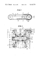
- FIG. 1 is a general elevational view of an endless track chassis using a drive device according to the invention
- FIG. 2 is a cross-section along II--II of FIG. 1, and,
- FIG. 3 repeats the embodiment shown in FIG. 2 but completing it by showing a variant embodiment of assembly.
- FIG. 1 shows a chassis adapted to carry a mechanical shovel with endless tracks, comprising a side frame 1, a main drive sprocket or toothed wheel 2 for driving the endless track 3, a tension wheel 4 for the track 3, and support rollers 5 for said track.
- a hydraulic motor 6 drives a pinion 7 which meshes directly with the main drive sprocket 2.
- the side frame 1 is made up as a beam comprising two vertical plates 8 and 9 the outer faces 8a and 9a of which are accurately symmetrical with respect to the vertical median plane 10 of the side frame.
- Two identical bearing supports 11, are fitted by bolts 12 on the plates 8 and 9 so as to be situated symmetrically with respect to the plane 10.
- two other identical bearing supports 13 are fitted by bolts 14 on the plates 8 and 9, also symmetrically with respect to the plane 10.
- the main drive sprocket 2 is composed by a toothed wheel centre supporting teeth 16 and having a central bore 17 force-fitted on an axis 18.
- the assembly has a plane of symmetry and is supported by ball bearings 19 placed in the bearing supports 11, so as to cause the said plane of symmetry to coincide with the plane 10.
- Bearing caps 20 hold the ball bearings 19 in position, whilst protecting them, whereas sealing devices 21 are interposed between the axis 18 and the main drive sprocket 2, and between the axis 18 and each bearing support 11.
- the pinion 7 is unitary with the axle 22 about which it rotates.
- the pinion 7 and the axle 22 have a plane of symmetry and are supported by ball bearings 23 placed in the bearing supports 13, so as to cause the said plane of symmetry to coincide with the plane 10.
- Sealing devices 24 comprising sealing gaskets are interposed between the axle 22 and the pinion 7 proper, on the one hand, and between the axle 22 and each bearing support 13 on the other hand.
- FIG. 2 The arrangement illustrated in FIG. 2 is that in which the output shaft 30 of the motor 6 is also provided with grooves 31 which cooperate with the grooves 29 to make said shaft 30 fast in rotation with the axle 22 of the pinion.
- the crankcase of the motor 6 is, itself, secured by means of screws 32 on the flange 26 welded to the plate 9.
- the grooves 29 provided on the other end of the axle 22 are inoperative and protected by a cover 33 secured by bolts 34 on the flange 26 welded on the plate 8.
- FIG. 3 which is otherwise identical to that shown in FIG. 2, shows one of the functions which can be assumed by these grooves.
- a disc brake stirrup piece 35 is secured by means of screws 36 on the flange 26 welded to the plate 8.
- This stirrup piece supports brake pads 37 arranged on either sides of a brake disc 38, the grooves 39 provided in the hub 40 of which cooperate with the said grooves 29 in making the disc 38 fast in rotation with the axle 22.
- a brake piston 41 moves inside a cylinder 42 provided in the stirrup piece 35, opposite at least one of the pads 37. Said cylinder 42 is furthermore in selective communication with a source of pressurized fluid indicated by arrow 43.
- the main drive sprocket 2 rests, symmetrically, on the bearing supports 11, instead of overhanging as in many prior arrangements, this permitting to adopt supports 11 and ball bearings 19 of reduced dimensions with respect to corresponding elements in said prior arrangements.
- the position of the pinion 7 in the plane of symmetry 10 of the frame 1 contributes to giving a compact and well protected assembly.
Landscapes
- Engineering & Computer Science (AREA)
- Chemical & Material Sciences (AREA)
- Combustion & Propulsion (AREA)
- Transportation (AREA)
- Mechanical Engineering (AREA)
- Gears, Cams (AREA)
- Gear Transmission (AREA)
- Retarders (AREA)
- Arrangement Of Transmissions (AREA)
Applications Claiming Priority (2)
| Application Number | Priority Date | Filing Date | Title |
|---|---|---|---|
| FR7919064A FR2461632A1 (fr) | 1979-07-24 | 1979-07-24 | Dispositif d'entrainement d'une chenille |
| FR7919064 | 1979-07-24 |
Publications (1)
| Publication Number | Publication Date |
|---|---|
| US4418775A true US4418775A (en) | 1983-12-06 |
Family
ID=9228229
Family Applications (1)
| Application Number | Title | Priority Date | Filing Date |
|---|---|---|---|
| US06/168,252 Expired - Lifetime US4418775A (en) | 1979-07-24 | 1980-07-10 | Endless track drive device |
Country Status (9)
| Country | Link |
|---|---|
| US (1) | US4418775A (fr) |
| JP (1) | JPS5625024A (fr) |
| BE (1) | BE884438A (fr) |
| BR (1) | BR8004549A (fr) |
| DE (1) | DE3027702A1 (fr) |
| ES (1) | ES8104099A1 (fr) |
| FR (1) | FR2461632A1 (fr) |
| GB (1) | GB2055336A (fr) |
| IT (1) | IT1128963B (fr) |
Cited By (4)
| Publication number | Priority date | Publication date | Assignee | Title |
|---|---|---|---|---|
| WO1989005751A1 (fr) * | 1987-12-22 | 1989-06-29 | Caterpillar Inc. | Mecanisme de suspension pour un vehicule a chenille |
| US4843910A (en) * | 1987-10-19 | 1989-07-04 | Unit Rig & Equipment | Pinion gear speed disc brake |
| US5050710A (en) * | 1990-04-10 | 1991-09-24 | Caterpillar Inc. | Wet disc brake mechanism |
| US20030226697A1 (en) * | 2002-05-17 | 2003-12-11 | Macmoter S.P.A. | Tracked vehicle |
Families Citing this family (5)
| Publication number | Priority date | Publication date | Assignee | Title |
|---|---|---|---|---|
| JPS60257509A (ja) * | 1984-06-04 | 1985-12-19 | 松下電器産業株式会社 | シ−ト積層法 |
| JP2513377Y2 (ja) * | 1989-04-27 | 1996-10-02 | 株式会社小松製作所 | 履帯式車輛の懸架駆動装置 |
| IT201700031156A1 (it) * | 2017-03-21 | 2018-09-21 | Luigi Longo | Trattore Autonomo |
| CN110171496B (zh) * | 2018-09-10 | 2024-05-07 | 襄阳忠良工程机械有限责任公司 | 一种可拆分式扒装机履带底盘 |
| SE545228C2 (en) * | 2021-03-25 | 2023-05-30 | Bae Systems Haegglunds Ab | Track assembly for a tracked vehicle |
Citations (9)
| Publication number | Priority date | Publication date | Assignee | Title |
|---|---|---|---|---|
| US674737A (en) * | 1900-11-09 | 1901-05-21 | Alvin O Lombard | Logging-engine. |
| US1363756A (en) * | 1918-09-03 | 1920-12-28 | Ruppert Frank | Tractor attachment |
| US1853308A (en) * | 1930-04-12 | 1932-04-12 | Walter G Humphreys | Sprocket wheel |
| US3168929A (en) * | 1958-11-07 | 1965-02-09 | Isaac J Wardle | Drive suspension for a track laying vehicle |
| US3486574A (en) * | 1968-06-26 | 1969-12-30 | Harnischfeger Corp | Drive mechanism for crawler tracks |
| US3580345A (en) * | 1969-06-11 | 1971-05-25 | American Hoist & Derrick Co | Disc brake for track-driven machine |
| US3785449A (en) * | 1971-08-27 | 1974-01-15 | Rockwell International Corp | Self-contained power transmitting assembly |
| US3872939A (en) * | 1974-02-21 | 1975-03-25 | Harnischfeger Corp | Modular final drive for track type vehicles |
| JPS527535A (en) * | 1975-07-02 | 1977-01-20 | Ishikawajima Kenki Kk | Drive system for catapillar type construction system vehicle |
-
1979
- 1979-07-24 FR FR7919064A patent/FR2461632A1/fr not_active Withdrawn
-
1980
- 1980-07-09 GB GB8022488A patent/GB2055336A/en not_active Withdrawn
- 1980-07-10 US US06/168,252 patent/US4418775A/en not_active Expired - Lifetime
- 1980-07-21 ES ES493553A patent/ES8104099A1/es not_active Expired
- 1980-07-22 BR BR8004549A patent/BR8004549A/pt unknown
- 1980-07-22 DE DE19803027702 patent/DE3027702A1/de not_active Withdrawn
- 1980-07-23 BE BE0/201500A patent/BE884438A/fr unknown
- 1980-07-23 IT IT68181/80A patent/IT1128963B/it active
- 1980-07-24 JP JP10063180A patent/JPS5625024A/ja active Pending
Patent Citations (9)
| Publication number | Priority date | Publication date | Assignee | Title |
|---|---|---|---|---|
| US674737A (en) * | 1900-11-09 | 1901-05-21 | Alvin O Lombard | Logging-engine. |
| US1363756A (en) * | 1918-09-03 | 1920-12-28 | Ruppert Frank | Tractor attachment |
| US1853308A (en) * | 1930-04-12 | 1932-04-12 | Walter G Humphreys | Sprocket wheel |
| US3168929A (en) * | 1958-11-07 | 1965-02-09 | Isaac J Wardle | Drive suspension for a track laying vehicle |
| US3486574A (en) * | 1968-06-26 | 1969-12-30 | Harnischfeger Corp | Drive mechanism for crawler tracks |
| US3580345A (en) * | 1969-06-11 | 1971-05-25 | American Hoist & Derrick Co | Disc brake for track-driven machine |
| US3785449A (en) * | 1971-08-27 | 1974-01-15 | Rockwell International Corp | Self-contained power transmitting assembly |
| US3872939A (en) * | 1974-02-21 | 1975-03-25 | Harnischfeger Corp | Modular final drive for track type vehicles |
| JPS527535A (en) * | 1975-07-02 | 1977-01-20 | Ishikawajima Kenki Kk | Drive system for catapillar type construction system vehicle |
Cited By (6)
| Publication number | Priority date | Publication date | Assignee | Title |
|---|---|---|---|---|
| US4843910A (en) * | 1987-10-19 | 1989-07-04 | Unit Rig & Equipment | Pinion gear speed disc brake |
| WO1989005751A1 (fr) * | 1987-12-22 | 1989-06-29 | Caterpillar Inc. | Mecanisme de suspension pour un vehicule a chenille |
| US4881609A (en) * | 1987-12-22 | 1989-11-21 | Caterpillar Inc. | Suspension mechanism for a track-type vehicle |
| US5050710A (en) * | 1990-04-10 | 1991-09-24 | Caterpillar Inc. | Wet disc brake mechanism |
| US20030226697A1 (en) * | 2002-05-17 | 2003-12-11 | Macmoter S.P.A. | Tracked vehicle |
| US7086490B2 (en) * | 2002-05-17 | 2006-08-08 | Macmoter S.P.A. | Tracked vehicle |
Also Published As
| Publication number | Publication date |
|---|---|
| ES493553A0 (es) | 1981-04-16 |
| JPS5625024A (en) | 1981-03-10 |
| FR2461632A1 (fr) | 1981-02-06 |
| ES8104099A1 (es) | 1981-04-16 |
| GB2055336A (en) | 1981-03-04 |
| BR8004549A (pt) | 1981-02-03 |
| IT1128963B (it) | 1986-06-04 |
| BE884438A (fr) | 1981-01-23 |
| DE3027702A1 (de) | 1981-02-12 |
| IT8068181A0 (it) | 1980-07-23 |
Similar Documents
| Publication | Publication Date | Title |
|---|---|---|
| US4418775A (en) | Endless track drive device | |
| GB1448552A (en) | Modular drive unit for the track assembly of track type vehicles | |
| GB1356106A (en) | Loop driven vehicles | |
| FR3088042B1 (fr) | Bogie pour vehicule ferroviaire | |
| US5111601A (en) | Excavation device with rotary cutter having a horizontal axis | |
| KR100271815B1 (ko) | 장궤식 차량의 주행장치 | |
| US3773128A (en) | Modular final drive for a track-type vehicle | |
| US3901336A (en) | Drive unit for crawler vehicle | |
| US3580345A (en) | Disc brake for track-driven machine | |
| US3810517A (en) | Loader drive | |
| US2732641A (en) | Jespersen | |
| US2997966A (en) | Crane bridge | |
| GB1565648A (en) | Joints | |
| US3209871A (en) | Drive arrangement for track working machines and the like | |
| US3963278A (en) | Track roller frame and final case mounting | |
| US3662847A (en) | Track roller shaft mounting | |
| GB1344693A (en) | Rail vehicles | |
| SU765090A2 (ru) | Движитель | |
| SU396296A1 (ru) | ПРИВОД мостового КРАНА-ШТАБЕЛЕРА | |
| SU522986A1 (ru) | Гусенична ходова часть транспортного средства с измен емой колеей | |
| JPH02231279A (ja) | 土工機械の無限軌道チエーンの鎖リンクを結合しかつ運動させるための機構 | |
| SU1027075A1 (ru) | Самоходный сельскохоз йственный агрегат | |
| SU526540A1 (ru) | Гусеничный движитель снегоходного транспортного средства | |
| JP3714637B2 (ja) | 装軌式車両の上転輪構造 | |
| JPH0142871B2 (fr) |
Legal Events
| Date | Code | Title | Description |
|---|---|---|---|
| STCF | Information on status: patent grant |
Free format text: PATENTED CASE |