US4429962A - Sound motion picture apparatus with removable cartridge - Google Patents
Sound motion picture apparatus with removable cartridge Download PDFInfo
- Publication number
- US4429962A US4429962A US06/298,088 US29808881A US4429962A US 4429962 A US4429962 A US 4429962A US 29808881 A US29808881 A US 29808881A US 4429962 A US4429962 A US 4429962A
- Authority
- US
- United States
- Prior art keywords
- cartridge
- film
- housing
- aperture
- sound
- Prior art date
- Legal status (The legal status is an assumption and is not a legal conclusion. Google has not performed a legal analysis and makes no representation as to the accuracy of the status listed.)
- Expired - Fee Related
Links
- 238000003780 insertion Methods 0.000 claims description 3
- 230000037431 insertion Effects 0.000 claims description 3
- 239000013536 elastomeric material Substances 0.000 claims description 2
- 230000003287 optical effect Effects 0.000 claims 5
- 229920001084 poly(chloroprene) Polymers 0.000 claims 1
- 239000004033 plastic Substances 0.000 description 6
- 230000000875 corresponding effect Effects 0.000 description 4
- 239000000463 material Substances 0.000 description 3
- 230000015572 biosynthetic process Effects 0.000 description 2
- 238000010276 construction Methods 0.000 description 2
- 230000000994 depressogenic effect Effects 0.000 description 2
- 238000010586 diagram Methods 0.000 description 2
- 238000005755 formation reaction Methods 0.000 description 2
- 238000012986 modification Methods 0.000 description 2
- 230000004048 modification Effects 0.000 description 2
- JOYRKODLDBILNP-UHFFFAOYSA-N Ethyl urethane Chemical compound CCOC(N)=O JOYRKODLDBILNP-UHFFFAOYSA-N 0.000 description 1
- XAGFODPZIPBFFR-UHFFFAOYSA-N aluminium Chemical compound [Al] XAGFODPZIPBFFR-UHFFFAOYSA-N 0.000 description 1
- 229910052782 aluminium Inorganic materials 0.000 description 1
- 230000004323 axial length Effects 0.000 description 1
- 230000002596 correlated effect Effects 0.000 description 1
- 230000000881 depressing effect Effects 0.000 description 1
- 229920001971 elastomer Polymers 0.000 description 1
- 238000001746 injection moulding Methods 0.000 description 1
- 238000002955 isolation Methods 0.000 description 1
- 230000000873 masking effect Effects 0.000 description 1
- 238000000034 method Methods 0.000 description 1
- 238000000465 moulding Methods 0.000 description 1
- 229920002379 silicone rubber Polymers 0.000 description 1
- 239000004945 silicone rubber Substances 0.000 description 1
- 239000000725 suspension Substances 0.000 description 1
Images


Classifications
-
- G—PHYSICS
- G03—PHOTOGRAPHY; CINEMATOGRAPHY; ANALOGOUS TECHNIQUES USING WAVES OTHER THAN OPTICAL WAVES; ELECTROGRAPHY; HOLOGRAPHY
- G03B—APPARATUS OR ARRANGEMENTS FOR TAKING PHOTOGRAPHS OR FOR PROJECTING OR VIEWING THEM; APPARATUS OR ARRANGEMENTS EMPLOYING ANALOGOUS TECHNIQUES USING WAVES OTHER THAN OPTICAL WAVES; ACCESSORIES THEREFOR
- G03B19/00—Cameras
- G03B19/18—Motion-picture cameras
Definitions
- the present invention relates to motion-picture apparatus.
- the invention relates to motion-picture apparatus having removable cartridges.
- this invention relates to sound motion picture apparatus having removable cartridges.
- a more particular object of the invention is to provide a motion-picture apparatus with removable cartridges which incorporates the aforementioned improvements over the prior art.
- Still a more specific object is to provide such an improved motion-picture apparatus as mentioned before, which provides sound accompaniment to the motion picture being shown.
- a concomitant object of the invention is to provide an improved motion-picture apparatus of the type under discussion, which is of simple and reliable construction.
- Yet a further object is to provide a motion-picture apparatus as outlined above, which is inexpensive to produce.
- a motion-picture apparatus in combination, a housing; a cartridge removably mountable in said housing and including an aperture, a length of motion-picture film in the cartridge, means for advancing the film frame-wise past the aperture; cooperating means on the housing and cartridge for operating the advancing means and means for reproducing a sound track which is correlatable with the action on the length of motion-picture film.
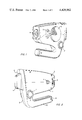
- FIG. 1 is a right-side perspective view of a motion-picture apparatus embodying the invention
- FIG. 2 is a left-side view of the apparatus in FIG. 1;
- FIG. 3 is a schematic, exploded diagram, showing the motor drive of the apparatus in FIGS. 1 and 2;
- FIG. 4 is a schematic exploded diagram, showing the details of the replaceable sound and motion-picture cartridges for use in the apparatus of FIGS. 1-3.
- FIGS. 1 and 2 provide two perspective views of the apparatus according to the invention, in operative position.
- the shape and configuration illustrated in these Figures need by no means be as shown.
- the apparatus has a housing composed of two shell-shaped parts 1, 2 which, when their open sides face one another and the parts are held together in suitable manner (via e.g. the screws 3) will constitute the illustrated hollow housing.
- the parts 1, 2 may be made of any suitable material (e.g. aluminum, synthetic plastic) and be produced by any suitable method (e.g. press-molding, injection molding).
- the housing has a lens assembly 4 which can be focussed by means of a knurled wheel 5 or similar device; since these may be similar to the elements 41, 42 described in U.S. Pat. No. 3,791,723, a more detailed description herein is not needed.
- the housing has an opening 6 for insertion of one of the interchangeable film cartridges 7.
- One side is provided near the lens assembly 4 with an opening 8 (which may be closed by a transparent cover) through which light can enter to illuminate the film (to be discussed later) in the cartridge 7.
- Reference numeral 9 identifies a perforated grill through which sound reaches the user; this could be omitted in favor of a simple opening.
- the handle 10 is hollow to form a battery compartement.
- FIG. 3 shows the motor arrangement and electrical circuit used in the apparatus of FIGS. 1 and 2.
- Motor 11 is mounted in a transverse space of the housing 1, 2 which is closed off at both ends by end covers 12 (see FIGS. 1 and 2).
- washers 13, 14 of rubber or of synthetic elastomeric material are interposed between the ends of motor 11 and end covers 12; the latter mount the motor 11 in the housing 1, 2.
- Washers 13, 14 provide vibration-free suspension of motor 11 in the housing 1, 2.
- Batteries 15 are inserted into the hollow interior of handle 10.
- One of the motor leads 16 has a battery contact strip 17 for contact with the end of one of the batteries.
- the other motor lead 18 carries an electrical contact 19 which is normally out of contact with the positive pole of the other battery 15 by an interposed resiliently compressible cellular-plastic washer 20 the axial thickness of which is slightly greater than the axial length of positive battery pole 21.
- the contact 19 is closest to the open end of the hollow handle 10, i.e. the left-hand end in FIG. 1. Inserted into this open end is an axially slidable pushbutton 22 which is held in place (so that it cannot fall out) by the usual button-surround 23 or in other suitable manner. When the button 22 is depressed inwardly, it presses contact 19 against washer 20. This causes the latter to be compressed sufficiently so that contact 19 can engage battery pole 21 through the center opening of washer 20 and complete the electrical circuit of motor 11.
- a shaft 22 which is mounted in one of the two housing shells 1, 2.
- a helical spring 23 surrounds the shaft 22 and is terminated with a washer 24.
- a drive wheel 25 is turnably mounted on the free end of shaft 22 (above washer 24) and is held in position by a circlip 26 snapped into a circumferential groove adjacent the free end of shaft 22.
- the drive wheel 25 can yield in direction towards the non-free end of shaft 22 (i.e. the end mounted in one of the housing shells) against the action of spring 23 when subjected to requisite pressure.
- the arrangement is such that such pressure is exerted by insertion of a cartridge 7 into the opening 6.
- the drive wheel 25 then recedes just sufficiently to let the cartridge 7 slide by it; when the cartridge is fully inserted, drive nubs 7 on wheel 25 will be located opposite cooperating formations (still to be discussed) on the cartridge 7.
- Wheel 25 is driven by a relatively stiff endless urethane drive belt 28 which surrounds the wheel 25 and the shaft of motor 11 (or a pulley thereon). Thus, depressing of push button 22 results in rotation of drive wheel 25.
- FIG. 4 shows one of the replaceable cartridges (all identical, except for the subject matter on the endless film loop and the associated sound track) for use in the apparatus of FIGS. 1-3.
- Reference numerals 40 and 41 identify the cartridge case and the cover of the same. Both may be of synthetic plastic material. Molded into the interior of the case 40 is a film guide track 42. The endless loop of motion-picture film 43 is coiled inside a hollow cap 44, a projection 45 of which is inserted into a corresponding hole 46 in case 40. The film strip is then withdrawn from the loop 43 located in cap 44 along guide path 47 and passes an opening 48 of the case 40. Mounted (usually formed integrally with case 40) behind opening 48 is an inclined boss 49 which is hollow underneath (as indicated by the phantom line 50); the inclined surface of boss 49 carries or is formed as a mirror of any kind (i.e. glass-mirror, metallized plastic, or the like).
- a metallic or synthetic plastic plate 51 Located behind the opening 48 is a metallic or synthetic plastic plate 51 (positioned to be immovable) provided with a cut-out 52 corresponding exactly or at least generally to opening 48.
- Plate 51 further has a single hole 53 in which a single film-ratchet pin 54 is mounted. Because an integral formation of pin 54 with plate 51, or direct-contact mounting of the two would result in excessive ratcheting noise (masking the sound track), the pin 54 is shock-mounted in hole 53 by means of silicone rubber. It should be noted, incidentally, that plate 51 could be omitted and hole 53 directly formed in case 40 laterally of the opening 48, in which case the pin 54 would be shock-mounted in this hole in case 40.
- the pin 54 of course cooperates with the perforations 43a in film 43 as the film is pulled past it in a manner still to be described.
- the film After moving past the pin 54, the film returns via a film guide track 55 to the interior of cap 44, to be wound up therein. In so doing it must pass around a curved arm 56 (to emerge at 57 and travel to track 55) of a double-curved lever 58 which is pivoted on a pivot pin 59 of the case 40.
- the other arm 60 of lever 58 carries a spring 61 which bears against the adjacent side 40a of the case 40.
- the advancing film 43 tends to pivot the lever 58 anti-clockwise; since this is resisted by the spring 61, the film 43 is always maintained in taut condition.
- the outlet of track 47 and the inlet of track 55 surround a hollow boss 62; a drive shaft 63 of a drive sprocket 64 (the latter located at the flat lateral side 40b of case 40) extends through the boss 62 where it is coupled with a tooth-type sprocket 65 having on its shaft a longitudinally extending key 66.
- the teeth of sprocket 65 engage with the perforations 43a to advance the film 43.
- a washer 67 is slipped onto the shaft of sprocket 65 and has a cut-out corresponding to key 66 so that washer 67 can turn with, but not relative to, the sprocket 65. Washer 67 also prevents film 43 from sliding up.
- a helical spring 62 Seated atop the washer 67 (and surrounding the shaft of sprocket 65) is a helical spring 62 which bears upon a record 70 carrying the sound track associated with the motion-picture on film 43, e.g. music and/or narration and/or live recordings.
- the center of record 70 has an opening and lateral cut-out corresponding to cut-out 68 so that the record is compelled to rotate with the sprocket 65, thereby assuring proper coordination between the motion-picture and the sound-track.
- This opening is surrounded over about half of its circumference by a first cam 71 which rises circumferentially in height.
- a member 72 has a center portion 73 receivable in the opening of record 70.
- Member 72 passes through 70 and fixes rigidly to the top of 63.
- Portion 73 carries a depending cam 74 which, except for the fact that it extends downwardly, is a counterpart to cam 71. Due to the fact that record 70 is seated on the helical spring 69, it can angularly tilt under certain conditions which will be described later.
- a tone arm 75 carrying a needle 76 for the soundtrack of record 70 is mounted to cover 41.
- a return spring 77 is provided for returning the tone arm to its starting position when the needle 76 reaches the innermost sound track on record 70 (and when the end of film 43 passes opening 48).
- arm 75 moves arm RA into the space between cams 71 and 74 to spread them apart. This shifts the record 70 downward, releasing the pressure on the tone arm exerted by record and speaker allowing the tone arm to return to its starting position under spring pressure.
- Tone arm 75 transmits its sound to a small e.g.
- cone-type speaker 78 which is mounted in an appropriate cut-out 79 of the cover 41; the cut-out 79 may remain open or provided with a grille in lieu of (or in addition to) the grill 9 of the apparatus in FIGS. 1-3.
- Abutment 80 on the underside of cover 41 delimits movement of the tone arm 75.
- Cover 41 also has a cut-out 81 for admission of light; this may simply remain open but, to protect the interior of the cartridge, had better be closed by a transparent sheet material 82 (a lens, or a plain piece of clear transparent synthetic plastic). Cover 41 is welded, screwed (as shown) or otherwise secured to case 40.
- a record needle return element 83 is provided, which is let into the lateral side 40b of case 40, so as to be flush with that side.
- the element 83 is located in the hollow interior of boss 49 and is pivotable about two pivot pins 84.
- the boss 49 has a cut-out 49a and the element 83 has an upstanding "tail" 83a.
- the tail 83a When depressed (pivoted) inwardly of case 40, the tail 83a will rise up through cut-out 49a, pressing at one side against the underside of record 70. This causes the record to tilt as mentioned before, freeing the needle 76 and tone arm 75 which can now return to their original starting position.
- the external reset button R simply interfaces with the member 83 (e.g. via an appropriate cam surface) so that the tone arm can be reset from the outside of housing 1, 2 without having to remove cartridge 7 therefrom.
- Portion H of the cartridge 9 is a convenient handle for inserting and removing the cartridge 7 from housing 1, 2.
- Batteries 15 are installed in the handle 10 of housing 1, 2 after removal of the push button and button surround, which are thereupon reinstalled.
- the housing 1, 2 is now ready to have a cartridge 7 inserted into it, with the opening 48 as the leading end.
- Cartridge 7 cams drive wheel 25 sideways so that it can slip past the wheel.
- the spring 23 presses drive wheel 25 firmly enough against the sprocket 64 to transmit rotary motion to the latter.
- the apparatus according to the invention is especially well suited for use with short (endless) lengths of film, which may depict literally anything desired.
- the film may be of a fairy tale or other subject matter appealing to a child. It may also be a training film, such as how to assemble a certain item of equipment, or how to play a certain sport (or certain aspects of a given type of sport). Since the apparatus operates quietly, especially due to the use of the single shock-mounted pin 54, as well as the mode or motor isolation, the attention of the user is not distracted from the sound tracks produced by the record 70.
Landscapes
- Physics & Mathematics (AREA)
- General Physics & Mathematics (AREA)
- Details Of Cameras Including Film Mechanisms (AREA)
Abstract
Description
Claims (10)
Priority Applications (2)
| Application Number | Priority Date | Filing Date | Title |
|---|---|---|---|
| US06/298,088 US4429962A (en) | 1981-08-31 | 1981-08-31 | Sound motion picture apparatus with removable cartridge |
| DE19813140255 DE3140255A1 (en) | 1981-08-31 | 1981-10-10 | "FILM CAMERA AND / OR VIEWER" |
Applications Claiming Priority (1)
| Application Number | Priority Date | Filing Date | Title |
|---|---|---|---|
| US06/298,088 US4429962A (en) | 1981-08-31 | 1981-08-31 | Sound motion picture apparatus with removable cartridge |
Publications (1)
| Publication Number | Publication Date |
|---|---|
| US4429962A true US4429962A (en) | 1984-02-07 |
Family
ID=23148977
Family Applications (1)
| Application Number | Title | Priority Date | Filing Date |
|---|---|---|---|
| US06/298,088 Expired - Fee Related US4429962A (en) | 1981-08-31 | 1981-08-31 | Sound motion picture apparatus with removable cartridge |
Country Status (2)
| Country | Link |
|---|---|
| US (1) | US4429962A (en) |
| DE (1) | DE3140255A1 (en) |
Citations (8)
| Publication number | Priority date | Publication date | Assignee | Title |
|---|---|---|---|---|
| US2196358A (en) | 1935-07-10 | 1940-04-09 | Askania Werke Ag | Motion picture camera |
| US3439598A (en) | 1966-05-25 | 1969-04-22 | Weitzner D | Camera and sound recording device |
| US3583797A (en) | 1968-11-19 | 1971-06-08 | Marvin Glass & Associates | Toy projector |
| US3923387A (en) | 1973-03-07 | 1975-12-02 | F J L Corp | Motion picture viewer with removable cartridge |
| US4013352A (en) | 1975-03-25 | 1977-03-22 | Monroy Jacob G | Self-blimped motion picture camera |
| US4121886A (en) | 1973-08-15 | 1978-10-24 | Panavision, Incorporated | Quiet motion picture camera |
| US4171881A (en) | 1978-01-30 | 1979-10-23 | Gaf Corporation | Hand held motion picture viewer |
| US4198134A (en) | 1974-12-23 | 1980-04-15 | Montron Corporation | Film cartridge |
-
1981
- 1981-08-31 US US06/298,088 patent/US4429962A/en not_active Expired - Fee Related
- 1981-10-10 DE DE19813140255 patent/DE3140255A1/en not_active Withdrawn
Patent Citations (8)
| Publication number | Priority date | Publication date | Assignee | Title |
|---|---|---|---|---|
| US2196358A (en) | 1935-07-10 | 1940-04-09 | Askania Werke Ag | Motion picture camera |
| US3439598A (en) | 1966-05-25 | 1969-04-22 | Weitzner D | Camera and sound recording device |
| US3583797A (en) | 1968-11-19 | 1971-06-08 | Marvin Glass & Associates | Toy projector |
| US3923387A (en) | 1973-03-07 | 1975-12-02 | F J L Corp | Motion picture viewer with removable cartridge |
| US4121886A (en) | 1973-08-15 | 1978-10-24 | Panavision, Incorporated | Quiet motion picture camera |
| US4198134A (en) | 1974-12-23 | 1980-04-15 | Montron Corporation | Film cartridge |
| US4013352A (en) | 1975-03-25 | 1977-03-22 | Monroy Jacob G | Self-blimped motion picture camera |
| US4171881A (en) | 1978-01-30 | 1979-10-23 | Gaf Corporation | Hand held motion picture viewer |
Also Published As
| Publication number | Publication date |
|---|---|
| DE3140255A1 (en) | 1983-03-10 |
Similar Documents
| Publication | Publication Date | Title |
|---|---|---|
| US4123065A (en) | Phonograph for use with record cartridges | |
| US4835619A (en) | Original reading apparatus | |
| US2681950A (en) | Transducing apparatus and magazine usable therewith | |
| JPS5955743U (en) | Camera exposure aperture frame | |
| US4451167A (en) | Printing device with swing-away cutter arrangement | |
| US4429962A (en) | Sound motion picture apparatus with removable cartridge | |
| US3287508A (en) | Sound reproducing device having a replaceable endless tape cartridge | |
| GB2141073A (en) | Ink ribbon feeding mechanism | |
| US4420762A (en) | Chart recorder | |
| GB2104274A (en) | Sound motion picture apparatus with removable cartridge | |
| US3484160A (en) | Audio-visual device | |
| US4396262A (en) | Hand held transparency projector with simple advance mechanism | |
| US3544038A (en) | Tape transport and cartridge | |
| US2449483A (en) | Animated picture viewing apparatus | |
| US3871757A (en) | Index means for audio-visual device | |
| US3240117A (en) | Slide holder with integral sound track | |
| US5774263A (en) | Stereoscopic film cartridge for a stereoscopic viewer | |
| US3583797A (en) | Toy projector | |
| US3963335A (en) | Magnetic tape carrier | |
| CN111781788A (en) | Story Projector | |
| CA1151916A (en) | Hand held transparency projector with simple advance mechanism | |
| US3362772A (en) | Self-threading motion picture projector | |
| US3393847A (en) | Film threading arrangement | |
| US4198134A (en) | Film cartridge | |
| JPH031749B2 (en) |
Legal Events
| Date | Code | Title | Description |
|---|---|---|---|
| AS | Assignment |
Owner name: KINBERG, BENJAMIN 200 FIFTH AVENUE NEW YORK, NY 1 Free format text: ASSIGNMENT OF ASSIGNORS INTEREST.;ASSIGNOR:BLAKE, JOSEPH W. III;REEL/FRAME:004132/0796 Effective date: 19830530 Owner name: KINBERG, BENJAMIN, NEW YORK Free format text: ASSIGNMENT OF ASSIGNORS INTEREST;ASSIGNOR:BLAKE, JOSEPH W. III;REEL/FRAME:004132/0796 Effective date: 19830530 |
|
| FEPP | Fee payment procedure |
Free format text: MAINTENANCE FEE REMINDER MAILED (ORIGINAL EVENT CODE: REM.); ENTITY STATUS OF PATENT OWNER: SMALL ENTITY |
|
| FEPP | Fee payment procedure |
Free format text: SURCHARGE FOR LATE PAYMENT, PL 96-517 (ORIGINAL EVENT CODE: M176); ENTITY STATUS OF PATENT OWNER: SMALL ENTITY |
|
| MAFP | Maintenance fee payment |
Free format text: PAYMENT OF MAINTENANCE FEE, 4TH YEAR, PL 96-517 (ORIGINAL EVENT CODE: M170); ENTITY STATUS OF PATENT OWNER: SMALL ENTITY Year of fee payment: 4 |
|
| FEPP | Fee payment procedure |
Free format text: PAYOR NUMBER ASSIGNED (ORIGINAL EVENT CODE: ASPN); ENTITY STATUS OF PATENT OWNER: SMALL ENTITY |
|
| FEPP | Fee payment procedure |
Free format text: MAINTENANCE FEE REMINDER MAILED (ORIGINAL EVENT CODE: REM.); ENTITY STATUS OF PATENT OWNER: SMALL ENTITY |
|
| FEPP | Fee payment procedure |
Free format text: SURCHARGE FOR LATE PAYMENT, PL 96-517 (ORIGINAL EVENT CODE: M176); ENTITY STATUS OF PATENT OWNER: SMALL ENTITY |
|
| MAFP | Maintenance fee payment |
Free format text: PAYMENT OF MAINTENANCE FEE, 8TH YEAR, PL 96-517 (ORIGINAL EVENT CODE: M171); ENTITY STATUS OF PATENT OWNER: SMALL ENTITY Year of fee payment: 8 |
|
| FEPP | Fee payment procedure |
Free format text: MAINTENANCE FEE REMINDER MAILED (ORIGINAL EVENT CODE: REM.); ENTITY STATUS OF PATENT OWNER: SMALL ENTITY |
|
| LAPS | Lapse for failure to pay maintenance fees | ||
| FP | Lapsed due to failure to pay maintenance fee |
Effective date: 19960207 |
|
| STCH | Information on status: patent discontinuation |
Free format text: PATENT EXPIRED DUE TO NONPAYMENT OF MAINTENANCE FEES UNDER 37 CFR 1.362 |