US4451192A - Silo unloader - Google Patents
Silo unloader Download PDFInfo
- Publication number
- US4451192A US4451192A US06/229,600 US22960081A US4451192A US 4451192 A US4451192 A US 4451192A US 22960081 A US22960081 A US 22960081A US 4451192 A US4451192 A US 4451192A
- Authority
- US
- United States
- Prior art keywords
- hopper
- silo
- arm
- sweep arm
- unloader
- Prior art date
- Legal status (The legal status is an assumption and is not a legal conclusion. Google has not performed a legal analysis and makes no representation as to the accuracy of the status listed.)
- Expired - Lifetime
Links
- 238000003860 storage Methods 0.000 claims abstract description 12
- 239000004460 silage Substances 0.000 claims description 15
- 239000000463 material Substances 0.000 description 33
- 229910000831 Steel Inorganic materials 0.000 description 3
- 235000013339 cereals Nutrition 0.000 description 3
- 238000013461 design Methods 0.000 description 3
- 238000012423 maintenance Methods 0.000 description 3
- 238000000034 method Methods 0.000 description 3
- 239000010959 steel Substances 0.000 description 3
- 230000015572 biosynthetic process Effects 0.000 description 2
- 239000002131 composite material Substances 0.000 description 2
- 239000004567 concrete Substances 0.000 description 2
- 238000005520 cutting process Methods 0.000 description 2
- 238000009826 distribution Methods 0.000 description 2
- 239000000843 powder Substances 0.000 description 2
- 239000011150 reinforced concrete Substances 0.000 description 2
- 241001474374 Blennius Species 0.000 description 1
- 235000019764 Soybean Meal Nutrition 0.000 description 1
- 238000013459 approach Methods 0.000 description 1
- 239000004568 cement Substances 0.000 description 1
- 238000010276 construction Methods 0.000 description 1
- 238000011161 development Methods 0.000 description 1
- 239000002657 fibrous material Substances 0.000 description 1
- 235000013312 flour Nutrition 0.000 description 1
- 238000005243 fluidization Methods 0.000 description 1
- 238000009415 formwork Methods 0.000 description 1
- 239000008187 granular material Substances 0.000 description 1
- 230000005484 gravity Effects 0.000 description 1
- 239000012770 industrial material Substances 0.000 description 1
- 230000003014 reinforcing effect Effects 0.000 description 1
- 238000009877 rendering Methods 0.000 description 1
- 239000004455 soybean meal Substances 0.000 description 1
Images


Classifications
-
- B—PERFORMING OPERATIONS; TRANSPORTING
- B65—CONVEYING; PACKING; STORING; HANDLING THIN OR FILAMENTARY MATERIAL
- B65G—TRANSPORT OR STORAGE DEVICES, e.g. CONVEYORS FOR LOADING OR TIPPING, SHOP CONVEYOR SYSTEMS OR PNEUMATIC TUBE CONVEYORS
- B65G65/00—Loading or unloading
- B65G65/30—Methods or devices for filling or emptying bunkers, hoppers, tanks, or like containers, of interest apart from their use in particular chemical or physical processes or their application in particular machines, e.g. not covered by a single other subclass
- B65G65/34—Emptying devices
- B65G65/40—Devices for emptying otherwise than from the top
- B65G65/42—Devices for emptying otherwise than from the top using belt or chain conveyors
- B65G65/425—Devices for emptying otherwise than from the top using belt or chain conveyors arranged to be movable
-
- B—PERFORMING OPERATIONS; TRANSPORTING
- B65—CONVEYING; PACKING; STORING; HANDLING THIN OR FILAMENTARY MATERIAL
- B65G—TRANSPORT OR STORAGE DEVICES, e.g. CONVEYORS FOR LOADING OR TIPPING, SHOP CONVEYOR SYSTEMS OR PNEUMATIC TUBE CONVEYORS
- B65G65/00—Loading or unloading
- B65G65/30—Methods or devices for filling or emptying bunkers, hoppers, tanks, or like containers, of interest apart from their use in particular chemical or physical processes or their application in particular machines, e.g. not covered by a single other subclass
- B65G65/34—Emptying devices
- B65G65/40—Devices for emptying otherwise than from the top
- B65G65/46—Devices for emptying otherwise than from the top using screw conveyors
- B65G65/466—Devices for emptying otherwise than from the top using screw conveyors arranged to be movable
Definitions
- the invention relates to storage silos and to bottom unloaders for such storage silos.
- Known methods of bottom unloading non free-flowing materials are based on altering the properties of the material, e.g. fluidisation of cement or flour with air, or the use of an agitator or cutter to break down the stable arch and restart flow, e.g. vibrators, augers and chain cutters, or the use of a steep sided mass flow hopper.
- an important feature in the design of an efficient bottom unloader is to arrange for the formation of a marginally stable arch or dome across most of the base area of the silo, so that the prime role of the unloader is to collect the loose material that falls from the underside of the dome, rather than the cutting of the compacted column of material.
- the end of the unloader should go only sufficiently close to the wall for it to undermine the edge of the arch or dome just enough to allow more material to drop therefrom.
- only the tip of the unloader is cutting the dense material and the power requirement is minimised as most of the energy required to break up the mass of material comes from its own weight as it descends in the silo. The gradual descent of the mass ensures that with each pass of the cutter new material has settled into position to be cut.
- the present invention provides the combination of a storage silo and a bottom unloader therefor wherein the base of the silo is formed as a hopper having a substantially central discharge outlet the unloader being arranged to project into the silo through the discharge outlet and comprising a sweep arm pivoted for rotation in the hopper about a vertical axis disposed centrally of the discharge outlet and for vertical movement away from the surface of the hopper.
- the invention provides the combination of a storage silo and a bottom unloader therefor wherein the base of the silo is formed as a hopper having a substantially central discharge outlet, the unloader comprising a sweep arm arranged to project into the silo through the discharge outlet and means for varying the effective length of the arm comprising a mounting supporting the arm for pivotal movement about a vertical axis disposed centrally of the discharge outlet, the mounting being arranged such that the length of the arm projecting into the silo can be altered.
- the invention provides the combination of a storage silo and bottom unloader therefor wherein the base of the silo is formed as a hopper having a substantially central discharge outlet the unloader being arranged to project into the silo through the discharge outlet and comprising a sweep arm pivoted for rotation in the hopper about a vertical axis disposed centrally of the discharge outlet and for vertical movement away from the surface of the hopper and means for varying the effective length of the arm comprising a mounting supporting the arm for pivotal movement about the centrally disposed vertical axis the mounting arrangement being such that the length of the arm projecting into the silo can be altered.
- the hopper extends over substantially the whole of the base of the silo and advantageously is conical in shape.
- the angle of the cone of the hopper will be chosen to suit the particular material to be stored but because of the assistance provided by the unloader can be substantially less than would be expected of a conventional hopper which must have a sufficiently steep angle to self empty.
- An important feature of the hopper is that there must be sufficient slope for the sweep arm to be withdrawn through the central discharge outlet.
- ⁇ hopper ⁇ as used in the specification and claims is to be construed accordingly.
- the unloader is mounted in a chamber below the silo.
- Means may be provided in the chamber for rotating the arm and for moving it vertically.
- the vertical movement is an angular movement about a central pivot.
- the sloping of the floor of the silo to form a hopper with a central discharge outlet permits the unloader to be introduced and withdrawn into the silo through the discharge outlet thus rendering the unloader accessible for maintenance and repair.
- Such an arrangement also permits adjustment of the effective length of the unloader so as to permit unloading with relatively low power consumption.
- the hopper bottom of the silo is a basically strong structural form whether it is of steel restrained by a ring beam or of reinforced concrete or composite double wedge construction.
- the central unloading of the silo together with a concentric undercutting of material within the silo renders more predictable the loads on the structure of the silo making the silo design cheaper and simpler.
- the unloader configuration may allow the effective length of the arm to be adjusted continuously it may be simpler and more robust to provide a limited range of settings.
- the sweep arm may be mounted on a floor stand in a chamber below the silo, independent of the hopper, and incorporating the motor drive etc.
- the sweep arm may be mounted on a floor stand in the chamber but with a hopper reinforcing ring being used to steady and drive the cutter assembly.
- the sweep arm may be suspended from the hopper.
- the sweep arm may comprise one or more vibrating or reciprocating bars; this is simple but is only really suitable for materials with hesitant flow properties which only require small energy inputs to keep them on the move. However vibration enables shallow hoppers to self empty.
- the vibrating or reciprocating bars may also be arranged to aerate the material in the silo.
- the sweep arm may be an auger. This is simpler than a chain cutter. The size and variation of pitch can be adjusted to suit the material to be stored. An auger can work with well chopped silage and other fibrous materials but it is best with granular/cohesive materials.
- the sweep arm can be a chain cutter since such will handle any material, though with silage it prefers it chopped.
- the sweep arm may either be a free cantilever unsupported on the hopper floor or may be partly skid-supported on the hopper surface.
- Steel hoppers are strong and light but require a strong ring beam especially if they have a shallow angle.
- Reinforced concrete hoppers can either be fairly massive but lightly reinforced or of more heavily reinforced twin wedge configuration.
- Composite hoppers of fabricated steel which can be assembled on site and then filled with concrete may be attractive since this arrangement would avoid the need for complex concrete formwork.
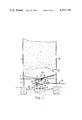
- FIG. 1 is a cross-sectional side elevation through the base of a hopper bottomed storage silo equipped with a centrally mounted sweep arm unloader;
- FIG. 2 is a scrap section on the line X--X of FIG. 1;
- FIG. 3 is a partly sectioned perspective view of a storage silo
- FIGS. 4a to 4c are scrap sectional side views of the base of the silo of FIG. 1 showing the unloader in different positions of operation;
- FIGS. 5a to 5e show five alternative forms of the base of the storage silo.
- FIGS. 1 to 3 show diagrammatically a cylindrical storage silo 1 formed at its base with a conical hopper 2 having a central discharge outlet 3.
- a chamber 4 through which the contents of the silo can be removed is disposed below the hopper 2.
- An unloader 5 is disposed centrally of the discharge outlet 3 on a mounting 11 on the floor 19 of the chamber 4.
- the unloader comprises a body 7 pivotally mounted on the stationary support 11, the body carrying at its upper end a sweep arm conveyor 6 which projects into the silo through the discharge outlet.
- the sweep arm 6 is mounted on the body 7 by means of a forked member 15 which is clamped to its lower surface near its rear end and which straddles and is pivoted to a tongue-like upward extension of the body 7 by means of a pin 14.
- the sweep arm 6 thus projects into the silo through the discharge outlet 3 and is arranged to lie generally parallel to the floor of the hopper 2 so that it can be rotated in the hopper to remove material from the silo through the discharge outlet.
- the sweep arm conveyor is driven in rotation by means of a motor 10 (e.g. an hydraulic motor) mounted on the stand 11 which drives a gear 9 which in turn engages a ring gear 8 fixed to the body 7.
- a motor 10 e.g. an hydraulic motor
- the sweep arm 6 has an endless chain 16 trained around its periphery which chain carries cutters 17 which cut and remove material from the silo, the chain 16 being driven in rotation by means of a motor 12 (e.g. an hydraulic motor) mounted on the rearward end of the arm 6.
- a motor 12 e.g. an hydraulic motor
- Bolts 18 by means of which the forked member 15 is clamped to the arm 6 permit the length of the arm 6 projecting into the silo through the discharge outlet to be altered as desired.
- the pivotal mounting of the sweep arm on the body 7 by means of pin 14 permits the sweep arm to be moved in a generally vertical plane away from the floor of the hopper, the inclination of the sweep arm being controlled by means of a screw jack 13.
- FIG. 1 of the drawings illustrates a situation in which the silo contains a mass of silage 22 which will weigh many tonnes and can thus tend to trap the sweep arm unloader.
- the wall of the silo at the junction between the hopper and the silo proper is inclined upwardly at a steep angle to form a fillet 21 to facilitate the creation of a semistable dome or arch of compacted silage over the sweep arm which can be made to collapse in a controlled manner by operation of the sweep arm so that the power requirement in operating the unloader is minimised.
- Reference 24 indicates an area of loose silage below the dome of compacted silage 23. Initially the sweep arm is operated partly retracted and as more material is removed from the silo the arm is gradually lengthened until it approaches the arch creating fillet 21 where the silage can be expected to be at maximum density. If the dome or arch of silage fails to collapse into the area 24 where it can readily be removed from the silo the arm can be pivoted upwardly as indicated in FIG. 4c to cause the collapse.
- the arm is resiliently biased upwardly so that it is free to pivot downwardly into contact with the floor of the hopper under the weight of silage collapsing on the arm.
- the adjustment of the working length of the cutter arm 6 may be effected by way of a screw 25 instead of by means of the clamp shown in FIGS. 1 and 2.
- the material in the silo is conveyed by the cutters 17 on the chain 16 to the central discharge outlet 3 where it drops onto a conveyor 20 for removal from the silo.
- FIG. 5a of the drawings there is shown a silo having a steeply inclined hopper defining a central discharge outlet and from which hopper the unloader 6 is suspended.
- the extremity of the hopper carries an outwardly extending annular flange 28 which forms a track for a carriage 26 which is supported for rotation on wheels 27 on the track 28.
- the carriage 26 supports the unloader 6 for lengthwise adjustment and for pivtol movement away from the surface of the hopper in the manner described in FIGS. 1 to 3. Rotation of the unloader may be achieved by a circular rack and pinion device.
- FIG. 5b of the drawings there is shown an arrangement of the kind described with reference to FIGS. 1 to 3 with the exception that the hopper is of a more pronounced slope.
- FIG. 5c of the drawings there is shown an arrangement of the kind shown with reference to FIGS. 1 to 3 of the drawings except that the unloader comprises a screw auger instead of a cutter chain.
- FIG. 5d of the drawings there is shown an arrangement of the kind generally described above except that the transitional area or fillet 21 between the vertical wall 1 and the hopper 2 is more pronounced than that described above.
- FIG. 5e of the drawings there is shown an arrangement generally similar to that of FIG. 4a but modified for use with a relatively shallow hopper.
- the track 28 is formed by the lower flange of an annular channel member 29 surrounding the discharge outlet 3 of the hopper.
- the sweep arm of the unloader can be removed from the silo through the discharge outlet for maintenance and repair and can in simple manner be extended or retracted to suit the particular operating conditions prevailing within the silo and can in simple manner be moved vertically should the operating conditions demand it.
Landscapes
- Engineering & Computer Science (AREA)
- Mechanical Engineering (AREA)
- Filling Or Emptying Of Bunkers, Hoppers, And Tanks (AREA)
Applications Claiming Priority (2)
| Application Number | Priority Date | Filing Date | Title |
|---|---|---|---|
| GB7916082 | 1979-05-09 | ||
| GB7916082 | 1979-05-09 |
Publications (1)
| Publication Number | Publication Date |
|---|---|
| US4451192A true US4451192A (en) | 1984-05-29 |
Family
ID=10505040
Family Applications (1)
| Application Number | Title | Priority Date | Filing Date |
|---|---|---|---|
| US06/229,600 Expired - Lifetime US4451192A (en) | 1979-05-09 | 1980-05-09 | Silo unloader |
Country Status (6)
| Country | Link |
|---|---|
| US (1) | US4451192A (de) |
| EP (1) | EP0028233A1 (de) |
| JP (1) | JPS56500444A (de) |
| AU (1) | AU529026B2 (de) |
| GB (1) | GB2060553B (de) |
| WO (1) | WO1980002416A1 (de) |
Cited By (23)
| Publication number | Priority date | Publication date | Assignee | Title |
|---|---|---|---|---|
| US4979861A (en) * | 1988-04-25 | 1990-12-25 | A. Ahlstrom Corporation | Discharge apparatus for a silo |
| WO1992022487A1 (en) * | 1991-06-12 | 1992-12-23 | Celltec Engineering Ab | A silo discharge arrangement |
| US5340033A (en) * | 1991-12-09 | 1994-08-23 | David Whitell | Granular material spreader |
| US20050161107A1 (en) * | 2004-01-23 | 2005-07-28 | Mark Turnbull | Apparatus and method for loading concrete components in a mixing truck |
| US20050201851A1 (en) * | 2003-01-24 | 2005-09-15 | Arvo Jonkka | Apparatus for storage and unloading of granular material |
| US20080131235A1 (en) * | 2006-12-01 | 2008-06-05 | Dome Technology, Llc | Mechanical reclaim systems with aeration and methods for use |
| US20080302635A1 (en) * | 2005-08-29 | 2008-12-11 | Kevin Hood | Air Cushion Conveyor Stacker Reclaimer Device and Method Thereof |
| US20100254790A1 (en) * | 2009-04-06 | 2010-10-07 | Tkachyk Ted F | Agitating Device for a Grain Bin Discharge Opening |
| US20120308349A1 (en) * | 2011-06-03 | 2012-12-06 | Rdp Technologies, Inc. | Sewage Silo With Centripetal Action Discharge Arm |
| US9327921B1 (en) * | 2014-10-21 | 2016-05-03 | Sukup Manufacturing Co. | Floating direct drive sweep assembly |
| US9809402B2 (en) | 2014-10-06 | 2017-11-07 | Sioux Steel Company | Segmented bin sweep system |
| US9815639B2 (en) | 2011-09-09 | 2017-11-14 | Sioux Steel Company | Modular storage bin sweep system |
| US9864344B2 (en) | 2013-10-16 | 2018-01-09 | Sioux Steel Company | System and method for multiple sweep proximity sensing and control |
| US10011442B2 (en) | 2014-02-10 | 2018-07-03 | Sioux Steel Company | Bin sweep support |
| US10220420B2 (en) | 2015-03-02 | 2019-03-05 | Sioux Steel Company | Bin sweep power transmission system |
| US10442641B2 (en) | 2014-12-02 | 2019-10-15 | Sioux Steel Company | Bin sweep system |
| US11104528B1 (en) | 2019-03-08 | 2021-08-31 | Sioux Steel Company | Bin sweep system with contoured paddles |
| US11267664B1 (en) | 2019-03-08 | 2022-03-08 | Sioux Steel Company | Bin sweep system with drive apparatus having enhanced slippage capability |
| US11299358B1 (en) | 2019-03-08 | 2022-04-12 | Sioux Steel Company | Storage bin sweep system with enhanced peripheral sweep capability |
| US11434083B2 (en) * | 2018-09-04 | 2022-09-06 | Bruks Rockwood, Llc | Reclaimers, reclaimer systems, and methods of using same |
| US11454444B1 (en) | 2019-03-08 | 2022-09-27 | Sioux Steel Company | Storage bin ventilation system and apparatus |
| US11618639B1 (en) | 2019-03-08 | 2023-04-04 | Sioux Steel Company | Storage bin sweep system with enhanced peripheral sweep capability |
| US12089538B1 (en) * | 2022-05-24 | 2024-09-17 | Ryan Vidrine | Vibratory attachment for a grain auger |
Families Citing this family (2)
| Publication number | Priority date | Publication date | Assignee | Title |
|---|---|---|---|---|
| US5099984A (en) * | 1990-06-20 | 1992-03-31 | Kuzub Danny S | Telescopic auger |
| AT512019A1 (de) * | 2011-09-22 | 2013-04-15 | Lasshofer Markus | Vorrichtung zum fördern von schüttgut |
Citations (13)
| Publication number | Priority date | Publication date | Assignee | Title |
|---|---|---|---|---|
| GB1051232A (de) * | ||||
| US3064831A (en) * | 1960-12-27 | 1962-11-20 | Butler Manufacturing Co | Unloader for storage containers |
| US3076567A (en) * | 1961-08-02 | 1963-02-05 | Butler Manufacturing Co | Adjustable capacity sweep conveyor for storage containers |
| DE1148942B (de) * | 1962-03-13 | 1963-05-16 | Heinrich Bakenhus | Vorrichtung zur Entleerung von Futtersilos |
| GB955786A (en) * | 1962-10-30 | 1964-04-22 | Butler Manufacturing Co | Adjustable capacity sweep conveyor for storage containers |
| US3190468A (en) * | 1963-11-20 | 1965-06-22 | Vilter Manufacturing Corp | Bin unloader |
| DE1218355B (de) * | 1964-08-22 | 1966-06-02 | Ludwig Deibel | Vorrichtung an Viehfuttersilos |
| FR1520775A (fr) * | 1967-03-03 | 1968-04-12 | Law Ets | Dispositif de manutention de matières en vrac, notamment de céréales |
| GB1185121A (en) * | 1968-03-05 | 1970-03-18 | Boythorpe Cropstores Ltd | Improvements in or relating to Auger Discharge of Material from Storage Silos |
| US3526328A (en) * | 1967-03-03 | 1970-09-01 | Etablis Law | Device for handling bulk materials,notably cereals |
| US3977543A (en) * | 1974-04-26 | 1976-08-31 | Weaver Richard L | Apparatus for discharging silage from a silo |
| US4146145A (en) * | 1977-07-28 | 1979-03-27 | Easton Harlan J | Bin unloader |
| US4286909A (en) * | 1978-04-12 | 1981-09-01 | Ab Siwertell | Apparatus for unloading bulk material from a storage space |
-
1980
- 1980-05-09 JP JP50099980A patent/JPS56500444A/ja active Pending
- 1980-05-09 AU AU59924/80A patent/AU529026B2/en not_active Ceased
- 1980-05-09 GB GB8039334A patent/GB2060553B/en not_active Expired
- 1980-05-09 US US06/229,600 patent/US4451192A/en not_active Expired - Lifetime
- 1980-05-09 WO PCT/GB1980/000086 patent/WO1980002416A1/en not_active Ceased
- 1980-11-17 EP EP80900833A patent/EP0028233A1/de not_active Withdrawn
Patent Citations (13)
| Publication number | Priority date | Publication date | Assignee | Title |
|---|---|---|---|---|
| GB1051232A (de) * | ||||
| US3064831A (en) * | 1960-12-27 | 1962-11-20 | Butler Manufacturing Co | Unloader for storage containers |
| US3076567A (en) * | 1961-08-02 | 1963-02-05 | Butler Manufacturing Co | Adjustable capacity sweep conveyor for storage containers |
| DE1148942B (de) * | 1962-03-13 | 1963-05-16 | Heinrich Bakenhus | Vorrichtung zur Entleerung von Futtersilos |
| GB955786A (en) * | 1962-10-30 | 1964-04-22 | Butler Manufacturing Co | Adjustable capacity sweep conveyor for storage containers |
| US3190468A (en) * | 1963-11-20 | 1965-06-22 | Vilter Manufacturing Corp | Bin unloader |
| DE1218355B (de) * | 1964-08-22 | 1966-06-02 | Ludwig Deibel | Vorrichtung an Viehfuttersilos |
| FR1520775A (fr) * | 1967-03-03 | 1968-04-12 | Law Ets | Dispositif de manutention de matières en vrac, notamment de céréales |
| US3526328A (en) * | 1967-03-03 | 1970-09-01 | Etablis Law | Device for handling bulk materials,notably cereals |
| GB1185121A (en) * | 1968-03-05 | 1970-03-18 | Boythorpe Cropstores Ltd | Improvements in or relating to Auger Discharge of Material from Storage Silos |
| US3977543A (en) * | 1974-04-26 | 1976-08-31 | Weaver Richard L | Apparatus for discharging silage from a silo |
| US4146145A (en) * | 1977-07-28 | 1979-03-27 | Easton Harlan J | Bin unloader |
| US4286909A (en) * | 1978-04-12 | 1981-09-01 | Ab Siwertell | Apparatus for unloading bulk material from a storage space |
Cited By (32)
| Publication number | Priority date | Publication date | Assignee | Title |
|---|---|---|---|---|
| US4979861A (en) * | 1988-04-25 | 1990-12-25 | A. Ahlstrom Corporation | Discharge apparatus for a silo |
| WO1992022487A1 (en) * | 1991-06-12 | 1992-12-23 | Celltec Engineering Ab | A silo discharge arrangement |
| US5447404A (en) * | 1991-06-12 | 1995-09-05 | Celltec Engineering Ab | Silo discharge arrangement |
| US5340033A (en) * | 1991-12-09 | 1994-08-23 | David Whitell | Granular material spreader |
| US7101140B2 (en) * | 2003-01-24 | 2006-09-05 | Metso Paper, Inc. | Apparatus for storage and unloading of granular material |
| US20050201851A1 (en) * | 2003-01-24 | 2005-09-15 | Arvo Jonkka | Apparatus for storage and unloading of granular material |
| US20060285943A1 (en) * | 2003-01-24 | 2006-12-21 | Metso Paper, Inc. | Apparatus for storage and unloading of granular material |
| US7234909B2 (en) | 2003-01-24 | 2007-06-26 | Metso Paper, Inc. | Apparatus for storage and unloading of granular material |
| US20050161107A1 (en) * | 2004-01-23 | 2005-07-28 | Mark Turnbull | Apparatus and method for loading concrete components in a mixing truck |
| US20080302635A1 (en) * | 2005-08-29 | 2008-12-11 | Kevin Hood | Air Cushion Conveyor Stacker Reclaimer Device and Method Thereof |
| US8177053B2 (en) * | 2005-08-29 | 2012-05-15 | Kevin Hood | Air cushion conveyor stacker reclaimer device and method thereof |
| US20080131235A1 (en) * | 2006-12-01 | 2008-06-05 | Dome Technology, Llc | Mechanical reclaim systems with aeration and methods for use |
| US8485770B2 (en) * | 2009-04-06 | 2013-07-16 | Ted F. Tkachyk | Agitating device for a grain bin discharge opening |
| US20100254790A1 (en) * | 2009-04-06 | 2010-10-07 | Tkachyk Ted F | Agitating Device for a Grain Bin Discharge Opening |
| US8939329B2 (en) * | 2011-06-03 | 2015-01-27 | Rdp Technologies, Inc. | Sewage silo with centripetal action discharge arm |
| WO2012166839A3 (en) * | 2011-06-03 | 2013-03-28 | Rdp Technologies, Inc. | Sewage silo with centripetal action discharge arm |
| US20120308349A1 (en) * | 2011-06-03 | 2012-12-06 | Rdp Technologies, Inc. | Sewage Silo With Centripetal Action Discharge Arm |
| US9815639B2 (en) | 2011-09-09 | 2017-11-14 | Sioux Steel Company | Modular storage bin sweep system |
| US9864344B2 (en) | 2013-10-16 | 2018-01-09 | Sioux Steel Company | System and method for multiple sweep proximity sensing and control |
| US10011442B2 (en) | 2014-02-10 | 2018-07-03 | Sioux Steel Company | Bin sweep support |
| US9809402B2 (en) | 2014-10-06 | 2017-11-07 | Sioux Steel Company | Segmented bin sweep system |
| US9327921B1 (en) * | 2014-10-21 | 2016-05-03 | Sukup Manufacturing Co. | Floating direct drive sweep assembly |
| US10442641B2 (en) | 2014-12-02 | 2019-10-15 | Sioux Steel Company | Bin sweep system |
| US10220420B2 (en) | 2015-03-02 | 2019-03-05 | Sioux Steel Company | Bin sweep power transmission system |
| US11434083B2 (en) * | 2018-09-04 | 2022-09-06 | Bruks Rockwood, Llc | Reclaimers, reclaimer systems, and methods of using same |
| US11104528B1 (en) | 2019-03-08 | 2021-08-31 | Sioux Steel Company | Bin sweep system with contoured paddles |
| US11267664B1 (en) | 2019-03-08 | 2022-03-08 | Sioux Steel Company | Bin sweep system with drive apparatus having enhanced slippage capability |
| US11299358B1 (en) | 2019-03-08 | 2022-04-12 | Sioux Steel Company | Storage bin sweep system with enhanced peripheral sweep capability |
| US11454444B1 (en) | 2019-03-08 | 2022-09-27 | Sioux Steel Company | Storage bin ventilation system and apparatus |
| US11618639B1 (en) | 2019-03-08 | 2023-04-04 | Sioux Steel Company | Storage bin sweep system with enhanced peripheral sweep capability |
| US11623829B2 (en) | 2019-03-08 | 2023-04-11 | Sioux Steel Company | Bin sweep system with contoured paddles |
| US12089538B1 (en) * | 2022-05-24 | 2024-09-17 | Ryan Vidrine | Vibratory attachment for a grain auger |
Also Published As
| Publication number | Publication date |
|---|---|
| GB2060553B (en) | 1983-04-20 |
| AU529026B2 (en) | 1983-05-19 |
| AU5992480A (en) | 1980-11-20 |
| EP0028233A1 (de) | 1981-05-13 |
| GB2060553A (en) | 1981-05-07 |
| JPS56500444A (de) | 1981-04-09 |
| WO1980002416A1 (en) | 1980-11-13 |
Similar Documents
| Publication | Publication Date | Title |
|---|---|---|
| US4451192A (en) | Silo unloader | |
| US4361254A (en) | Hopper for storing free flowing solid material | |
| US3456818A (en) | Grain auger apparatus | |
| US5098247A (en) | Device and method for outloading bulk materials | |
| JP2002524369A (ja) | ばら物荷役装置 | |
| US3509985A (en) | Conveyor loading and unloading apparatus | |
| US4015734A (en) | Sweep auger for bottom silo unloaders | |
| US5180272A (en) | Device and method for outloading bulk materials | |
| US3976176A (en) | Spiral chute device | |
| EP2036842B9 (de) | Stapelvorrichtung und Verfahren zum Ablegen von Material auf einem Stapel | |
| US3414142A (en) | Sweep arm bin unloader | |
| JPH0223448B2 (de) | ||
| CA1160590A (en) | Silo unloader | |
| US2755771A (en) | Rotary feed agitator for a self-feeding silo | |
| US4445814A (en) | Apparatus for depositing solid particulate material in a frustoconical pile | |
| JPS61502460A (ja) | ばら荷のための円形輪郭を有する貯蔵所 | |
| US4313706A (en) | Grain cake breaker | |
| CN109775162B (zh) | 具有平板基础式加速出料装置的钢板仓 | |
| US3493130A (en) | Bottom silo unloaders | |
| US3134491A (en) | Storage bin unloading apparatus | |
| CN221418811U (zh) | 一种物料用出料设备 | |
| RU2148315C1 (ru) | Бункерное устройство | |
| US2955720A (en) | Apparatus for establishing arching of fibrous material | |
| US3426924A (en) | Silo and unloader | |
| CN219525333U (zh) | 一种依附斜坡的节能高效运输机构 |
Legal Events
| Date | Code | Title | Description |
|---|---|---|---|
| STCF | Information on status: patent grant |
Free format text: PATENTED CASE |