US4470239A - Suspended ceiling grid system - Google Patents
Suspended ceiling grid system Download PDFInfo
- Publication number
- US4470239A US4470239A US06/214,250 US21425080A US4470239A US 4470239 A US4470239 A US 4470239A US 21425080 A US21425080 A US 21425080A US 4470239 A US4470239 A US 4470239A
- Authority
- US
- United States
- Prior art keywords
- webs
- flanges
- runners
- panels
- edges
- Prior art date
- Legal status (The legal status is an assumption and is not a legal conclusion. Google has not performed a legal analysis and makes no representation as to the accuracy of the status listed.)
- Expired - Lifetime
Links
Images


Classifications
-
- E—FIXED CONSTRUCTIONS
- E04—BUILDING
- E04B—GENERAL BUILDING CONSTRUCTIONS; WALLS, e.g. PARTITIONS; ROOFS; FLOORS; CEILINGS; INSULATION OR OTHER PROTECTION OF BUILDINGS
- E04B9/00—Ceilings; Construction of ceilings, e.g. false ceilings; Ceiling construction with regard to insulation
- E04B9/06—Ceilings; Construction of ceilings, e.g. false ceilings; Ceiling construction with regard to insulation characterised by constructional features of the supporting construction, e.g. cross section or material of framework members
- E04B9/065—Ceilings; Construction of ceilings, e.g. false ceilings; Ceiling construction with regard to insulation characterised by constructional features of the supporting construction, e.g. cross section or material of framework members comprising supporting beams having a folded cross-section
- E04B9/067—Ceilings; Construction of ceilings, e.g. false ceilings; Ceiling construction with regard to insulation characterised by constructional features of the supporting construction, e.g. cross section or material of framework members comprising supporting beams having a folded cross-section with inverted T-shaped cross-section
- E04B9/068—Ceilings; Construction of ceilings, e.g. false ceilings; Ceiling construction with regard to insulation characterised by constructional features of the supporting construction, e.g. cross section or material of framework members comprising supporting beams having a folded cross-section with inverted T-shaped cross-section with double web
-
- E—FIXED CONSTRUCTIONS
- E04—BUILDING
- E04B—GENERAL BUILDING CONSTRUCTIONS; WALLS, e.g. PARTITIONS; ROOFS; FLOORS; CEILINGS; INSULATION OR OTHER PROTECTION OF BUILDINGS
- E04B9/00—Ceilings; Construction of ceilings, e.g. false ceilings; Ceiling construction with regard to insulation
- E04B9/06—Ceilings; Construction of ceilings, e.g. false ceilings; Ceiling construction with regard to insulation characterised by constructional features of the supporting construction, e.g. cross section or material of framework members
- E04B9/12—Connections between non-parallel members of the supporting construction
- E04B9/122—Connections between non-parallel members of the supporting construction one member passing through the other member, both members laying at least partly in the same plane
Definitions
- the present invention relates to a supporting grid system for suspended ceilings and, more particularly, to an improvement in the construction of the ceiling tile supporting members which coact to define the suspended ceiling supporting network.
- suspended ceilings in building construction is well known.
- One mode of construction provides a metal framework with longitudinal runners and lateral cross members or runners disposed at right-angles thereto and fitted together in a lattice or grid network to thereby define a plurality of modular openings.
- the framework is supported by hangers from overhead structure and functions to support ceiling tiles or panels, flourescent light fixtures, ventilation fixtures, and the like.
- the runners and cross runners are usually of inverted T-shape with a pair of horizontally disposed flanges on opposite sides of a central upstanding, vertically disposed web section.
- the flanges are relatively wide in order to support the ceiling tiles while permitting sufficient clearance or tolerance between the edges of the tiles and the web sections. Architects frequently object to the appearance presented by such exposed flanges, and seek alternatives.
- Another known construction also employing rabbet-edged tiles, provides extruded metal runners and cross runners; each having inverted U-shaped tile supporting flanges, with the metal thicknessess of the legs thereof serving as the exposed outline for the suspended ceiling.
- the present invention provides a framework or grid for suspended ceilings wherein the tile supporting flanges of the main runners and the cross runners are relatively thin in width to provide an aesthetically pleasing appearance; while, at the same time, functioning to firmly and uniformly support the ceiling tiles in such a manner that the same are automatically centered within the modular opening.
- the use of standard-sized, straight-edged tiles is permitted, if desired, without any need to provide sufficient clearance to avoid lateral shifting and possible fall-through of the tiles.
- the structure of the present invention precludes the necessity of, and saves the added cost of, providing additional structure to hide from view the wide flanges of prior constructions.
- the invention also incorporates in the main runners and/or the cross runners relatively simple and inexpensive structure to permit lighting fixtures and the like to be easily and effectively hung therefrom, without the need for providing specially designed, costly adapters as typified by prior art constructions.
- the main runners and the cross runners of the present invention are each characterized by a pair of resilient webs depending downwardly and outwardly from an upper tubular bulb portion to a horizontally disposed, reduced-width, tile supporting flange portion at the lower extremity of each web.
- the flange portions are resiliently biased in an outward direction by the webs such that supporting forces are exerted on the ceiling tiles to thereby automatically center the same and uniformly support the same in their assembled position.
- thin-line, exposed flanges are observable to present a pleasing appearance without any sacrifice in the tile supporting requirements of the flanges.
- the interior space between the webs may be prepainted with the same color as the exposed flanges or with a contrasting color. In either case, from an observer's point of view, an aesthetically pleasing grid network is presented.
- the interior walls of the webs may be provided with screw-fastener guide means to permit easy installation of lighting fixtures and the like.
- Such guide means preferably comprise a plurality of relatively short curved recesses in the interior facing walls of each of the webs and extending downwardly and outwardly therewith to provide a composite tubular opening sufficient to receive and guide the screw-fastener into position.
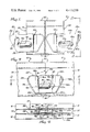
- FIG. 1 is an enlarged side elevational view of a main runner section constructed in accordance with the invention, with parts thereof broken away for ease of illustration;
- FIG. 2 is an end elevational view of the runner looking in the direction of line 2--2 of FIG. 1;
- FIG. 3 is a side elevational view, with parts thereof broken away, depicting a splice or connection between two main runners, each of which is characterized by the runner depicted in FIG. 1;
- FIG. 4 is a cross-sectional view taken substantially along line 4--4 of FIG. 3;
- FIG. 5 is an enlarged side elevational view of a cross runner constructed in accordance with the invention, with parts thereof broken away for ease of illustration;
- FIG. 6 is an end elevational view of the crossrunner looking in the direction of line 6--6 of FIG. 5;
- FIG. 7 is a partial fragmentary view of the main runner of FIG. 1 depicting one of a plurality of spaced slots in the webs thereof for receipt of adjacent cross runner sections;
- FIG. 8 is a fragmentary elevational view of adjacent cross runners in operative engagement with each other and with their intersecting main runner;
- FIG. 9 is a cross-sectional view taken along line 9--9 of FIG. 8;
- FIG. 10 is a fragmentary side elevational view of a main runner or a cross runner depicting the application thereto of means for guiding fixture-holding fasteners;
- FIG. 11 is a vertical cross-sectional view of one of the main runners or one of the cross runners depicting the manner in which a fixture is affixed thereto;
- FIG. 12 is a fragmentary view of the assembled adjacent cross runner sections depicting the application of a clip means for blocking from view the coupling structure which locks each of such cross runners together;
- FIG. 13 is a bottom fragmentary view looking in the direction of line 13--13 of FIG. 12;
- FIG. 14 is a fragmentary cross-sectional view of one of the main runners or cross runners depicting support of a standard size square-edged ceiling tile and a slightly modified flange construction;
- FIG. 15 is a view similar to FIG. 14 but depicting optional support of a rabbet-edged ceiling tile.
- a main supporting runner is formed to provide an upper tubular reinforcing bulb 12 or substantially circular cross-section (although other cross-sectional shapes would suffice), a pair of resilient webs 14 depending downwardly and outwardly from bulb 12 in substantial inverted V fashion, and horizontally disposed tile supporting flanges 16 integrally connecting to the lower extremities of each of webs 14 and extending outwardly therefrom.
- Main runner 10 can be fabricated from any single piece of any suitable material, such as thin gauge steel; however, the same is preferably rolled, folded and stamped from soft steel or the like. Alternatively, other well known methods of fabrication may be employed.
- the webs are inherently spring biased with a "memory” that causes them to normally maintain their spread apart position and, as such, they will offer an outward biasing force in response to inward movements.
- each web 14 is integrally provided with suitable splicing or clip means to permit adjacent main runners to be rigidly joined in abutting and aligned relationship, while effectively preventing any relative twisting therebetween.
- one pair of web ends 18 are provided with suitable locking projection tabs or stabs 20 slightly pressed from the plane of its respective web in one lateral direction and projecting outwardly therefrom to define an upper edge surface 22, a reduced length lower surface 24, and a forward edge surface 26 upwardly and outwardly directed from lower edge surface 24 to upper surface 22 via an outwardly curved guiding edge surface 28.
- An elongated central reinforcing rib 30 is pressed slightly out of the plane of stab 20 in said one lateral direction and contains at its end adjacent outer edge surface 26 a laterally curved, planar edged locking element 32 protruding from the plane of stab 20 in an opposite lateral direction to thereby define an abutment or stop 34.
- Each stab 20 further includes a tongue 35 pressed out of the plane thereof in one lateral direction leaving an abutment edge 36 that is substantially aligned with the projecting leading edge surfaces of the stab and is spaced inwardly of stop 34.
- the opposite pair of web ends 38 are each provided with similar locking projection tabs or stabs 20a, except that the same (including projecting edge surfaces 22a, 24a, 26a and 28a, reinforcing rib 30a, locking element 32a, stop 34a and tongue 35a) are slightly offset in lateral directions that are opposite to that of their corresponding structure on web ends 18. As depicted in FIGS.
- the arrangement is such that when adjacent main runner sections are brought together, the stabs on one pair of web ends 18 are guided through the tongues on the other pair of web ends 38 whereby the abutments 34 snap into locking engagement with the abutment edges 36a and the stabs on the other pair of web ends 38 are guided through the tongues on the other pair of web ends 18 whereby the abutments 34a snap into locking engagement with the abutment edges 36, thereby providing a main runner splice.
- the cross runners are provided with a reinforcing tubular bulb 42, a pair of resilient webs 44 and horizontally disposed tile supporting flanges 46 which are all formed in a manner similar to that of main runner 10; therefore, no further description of these elements is deemed necessary.
- each of the webs 44 are provided with suitable locking connectors, generally designated at 48, 48a, which, respectively project outwardly from their respective ends and are formed integral therewith.
- connectors 48, 48a at opposite ends of each cross runner 40 are slightly offset from the plane of their respective webs 44 in opposite lateral directions and are provided with substantially hook-shaped tabs defined by a leading curved edge 50, 50a; a flat bottom edge 52, 52a; and a web-gripping edge 53, 53a which, respectively, connects edges 50, 50a to edges 52, 52a.
- edges 53, 53a are inclined to follow the inclination angles of each of the main runner webs 14, as will become apparent hereinbelow.
- Each connector 48, 48a further includes transverse through openings 54, 54a located adjacent their respective curved edges 50, 50a.
- catches 56, 56a aligned with and inwardly spaced from their respective openings 54, 54a.
- Catches 56 at one end of cross runners 40 may be suitably pressed out of the plane of each of the connectors 48 in one lateral direction, whereas catches 56a at the other end of cross runners 40 may be suitably pressed out of the plane of each of the connectors 48 a in the opposite lateral direction.
- Such lateral offsetting of the catches 56, 56a provide the same with curved abutment edges 58, 58a, respectively.
- each main runner web 14 is provided with a plurality of longitudinally spaced cross runner slots 60 (only one of which being illustrated); the slots on one web being disposed for alignment with their corresponding slots on the other web.
- Each slot 60 is formed with a pair of curved side edges 62, a flat upper edge 64 and a notched lower edge 66 to thereby define substantially the profile of an inverted bottle.
- the spacing between top edge 64 and the bottom of lower edge 66 substantially corresponds to the vertical extent of the leading curved edges 50, 50a of the connectors 48, 48a.
- Adjacent cross runners 40 may be rigidly coupled to each other through slot 60 in locking engagement therewith to define the intersecting grid structure for supporting the ceiling tiles. Alternatively, only one cross runner may be locked through the slot 60, if desired or required. More specifically, as adjacent cross runners are joined together through slots 60 adjacent aligned connectors 48, 48a on each are snap-locked together by engagement of openings 54, 54a with their respective abutment edges 58a, 58 of catches 56a, 56, respectively, as clearly indicated in FIG. 9.
- the relationship between the connectors and the slots is such as to permit automatic straight-through insertion without the necessity of any manual squeezing of the cross runner webs.
- the cross runner flanges 46 are maintained substantially coplanar or flush with the main runner flanges 16 by means of an offset or relieved portion 68 on the ends of cross runner flanges 46.
- each main runner web 14 may be provided with a plurality of longitudinally spaced openings 70.
- Suitable hangers H may pass through selected openings 70 for suspending the main runners from overhead support structure, as is conventional.
- the tile supporting flanges on the main runners and the cross runners are substantially narrower (in a lateral sense) than would be required in constructions employing conventional inverted T-shaped members.
- the flanges on each side of the web must be sized to permit sufficient tolerance within the modular grid for adequate support of the tile, the flanges of the present invention need only be of a size sufficient for the actual support of the tile and not any larger to provide for such tolerances as typified by prior art constructions.
- the spring action of the resilient webs, on the main runners and the cross runners provides or permits automatic centering and support of the tiles without any need for greater flange widths.
- FIGS. 10 and 11 depict main runner and/or cross runner structure. Therefore, generic designation shall be employed to indicate various parts of such structure that are clearly common to both main runners and cross runners.
- the web W of either a main runner or a cross runner may be provided with a plurality of adjacent recesses or serrations 72.
- Each recess 72 is preferably formed integral with its respective web and pressed out of the inner surfaces thereof adjacent the bulb portion B to extend downwardly and outwardly therefrom to a point between the upper and lower extremities of the webs.
- Recesses 72 on each web W are disposed for alignment with corresponding recesses on the opposite web to thereby define composite channels or tubular openings for guiding and receiving suitable fasteners or metal screws 74. As depicted in FIG.
- the arrangement is such that a fixture or a support S for a partition head channel or the like may be brought into engagement with ceiling tiles T and affixed to runner bulbs B by means of the sheet metal screw or the like 74 which is guided through the composite openings defined by the facing recesses 72 and secured through the bulb portion B.
- a clip is provided for removable attachment to flanges 16 of main runner 10 to substantially span the gap between the flanges 46 of adjacent connected cross runners 40.
- clip 76 is fabricated of a suitable resilient, spring-like material and has a pair of upwardly and outwardly directed snap fingers 78 connecting to a pair of substantially planar horizontally disposed sections 80 which, in turn, connect to an upwardly directed and centrally located substantially inverted U-shaped portion 82 extending upwardly into the space between main runner webs 14.
- Inverted U-shaped portion 82 functions to simulate the appearance of the shadow space formed between the inner surfaces of oppositely inclined main runner webs 14.
- the exposed surfaces of flanges 16 and 46 may be prepainted or coated prior to forming with a color contrasting to that of the space between their respective webs 14 and 44.
- the main runners and the cross runners would have their flanges folded in such a manner as to reverse the surfaces thereof to enable one color to appear between the webs and the contrasting color exposed on the flanges.
- This folding arrangement has been disclosed throughout the drawings but is highlighted at F in FIG. 15. However, if it were desired to expose the same colors between the webs and on the exposed portions of the flanges, then the flanges could be folded opposite to the folds of FIG. 15 as depicted at F' in FIG. 14.
- FIG. 15 also illustrates the optional employment of rabbet-edged ceiling tiles T' for support by the main runner flanges and the cross runner flanges.
Landscapes
- Engineering & Computer Science (AREA)
- Architecture (AREA)
- Physics & Mathematics (AREA)
- Electromagnetism (AREA)
- Civil Engineering (AREA)
- Structural Engineering (AREA)
- Finishing Walls (AREA)
Priority Applications (3)
| Application Number | Priority Date | Filing Date | Title |
|---|---|---|---|
| US06/214,250 US4470239A (en) | 1980-12-08 | 1980-12-08 | Suspended ceiling grid system |
| CA000391727A CA1168013A (fr) | 1980-12-08 | 1981-12-08 | Grillage pour plafond suspendu |
| US06/358,894 US4484428A (en) | 1980-12-08 | 1982-03-17 | Suspended ceiling grid system |
Applications Claiming Priority (1)
| Application Number | Priority Date | Filing Date | Title |
|---|---|---|---|
| US06/214,250 US4470239A (en) | 1980-12-08 | 1980-12-08 | Suspended ceiling grid system |
Related Child Applications (1)
| Application Number | Title | Priority Date | Filing Date |
|---|---|---|---|
| US06/358,894 Continuation-In-Part US4484428A (en) | 1980-12-08 | 1982-03-17 | Suspended ceiling grid system |
Publications (1)
| Publication Number | Publication Date |
|---|---|
| US4470239A true US4470239A (en) | 1984-09-11 |
Family
ID=22798364
Family Applications (1)
| Application Number | Title | Priority Date | Filing Date |
|---|---|---|---|
| US06/214,250 Expired - Lifetime US4470239A (en) | 1980-12-08 | 1980-12-08 | Suspended ceiling grid system |
Country Status (2)
| Country | Link |
|---|---|
| US (1) | US4470239A (fr) |
| CA (1) | CA1168013A (fr) |
Cited By (18)
| Publication number | Priority date | Publication date | Assignee | Title |
|---|---|---|---|---|
| FR2524041A1 (fr) * | 1982-03-17 | 1983-09-30 | Donn Inc | Grille de support pour plafonds suspendus et plafonds suspendus mettant en oeuvre une telle grille |
| US4677802A (en) * | 1986-03-07 | 1987-07-07 | Chicago Metallic Corporation | Suspended ceiling system and runner |
| US4679375A (en) * | 1983-09-23 | 1987-07-14 | Donn Incorporated | Suspension ceiling grid system with narrow-faced grid |
| US4712350A (en) * | 1986-05-16 | 1987-12-15 | Chicago Metallic Corporation | Centering arrangement for T members of a suspended ceiling |
| US4794745A (en) * | 1986-12-15 | 1989-01-03 | National Rolling Mills Inc. | Tier drop grid system |
| EP0538915A1 (fr) * | 1991-10-21 | 1993-04-28 | Chicago Metallic Continental N.V. | Raccordement de profilés de faux plafonds et profilés utilisés à cet effet |
| US6477815B2 (en) | 2001-01-03 | 2002-11-12 | William Paul | Suspended ceiling grid structure with main runners incorporating coded matching indicia for receiving cross runners in desired spaced apart fashion |
| US6516582B2 (en) | 2001-01-03 | 2003-02-11 | William Paul | Wall angle for use in suspended ceiling grid structure and including multi-purpose measurement indicia such as differently configured indentation or punch-out portions |
| US6516581B2 (en) | 2001-01-03 | 2003-02-11 | William Paul | Wall angle for use in suspended ceiling grid structure and including multi-purpose measurement indicia |
| US6526716B2 (en) | 2001-01-03 | 2003-03-04 | William Paul | Suspended ceiling grid structure with main runners incorporating measurement indicia for establishing a border dimension for a engagement by a cross tee |
| US6729100B2 (en) | 2002-04-30 | 2004-05-04 | Usg Interiors, Inc. | Main tee splice |
| US20040194417A1 (en) * | 2003-04-01 | 2004-10-07 | William Paul | Wall angle and main tee for use in suspended ceiling grid structure and including multi-purpose measurement indicia |
| WO2008002658A3 (fr) * | 2006-06-28 | 2008-02-21 | Flex Ability Concepts L L C | Dispositif et procédé pour réaliser une structure courbe |
| US20080135712A1 (en) * | 2004-07-06 | 2008-06-12 | Dennis Raymond Prout | Spacing Device |
| US20100139189A1 (en) * | 2008-12-09 | 2010-06-10 | Usg Interiors, Inc. | Concealed suspension ceiling with downward removable panels |
| WO2013101461A1 (fr) * | 2011-12-29 | 2013-07-04 | Usg Interiors, Llc | Grille de plafond à profil unique |
| CN112081291A (zh) * | 2020-09-17 | 2020-12-15 | 广东五羊美特新型建材有限公司 | 一种龙骨弯头结构及吊顶龙骨系统 |
| CN113882577A (zh) * | 2021-10-27 | 2022-01-04 | 浙江亚厦装饰股份有限公司 | 一种吊顶总成 |
Families Citing this family (3)
| Publication number | Priority date | Publication date | Assignee | Title |
|---|---|---|---|---|
| CN107119841B (zh) * | 2017-02-28 | 2023-09-29 | 青岛有住信息技术有限公司 | 顶面饰面板安装卡接结构 |
| CN113818621B (zh) * | 2021-08-20 | 2024-06-21 | 浙江亚厦装饰股份有限公司 | 一种活动式内扣平接龙骨 |
| CN113775136B (zh) * | 2021-09-07 | 2024-06-25 | 浙江亚厦装饰股份有限公司 | 一种横龙骨跨接安装辅助模块及其安装方法 |
Citations (21)
| Publication number | Priority date | Publication date | Assignee | Title |
|---|---|---|---|---|
| US1253216A (en) * | 1915-05-03 | 1918-01-15 | Whitaker Glessner Company | Metal furring-strip. |
| US2191161A (en) * | 1939-02-04 | 1940-02-20 | Hippolyte W Romanoff | Interlocked structure |
| US2734127A (en) * | 1956-02-07 | naysmith | ||
| US3023865A (en) * | 1956-04-17 | 1962-03-06 | Hugo E Brandstetter | Suspended ceiling structure |
| US3202077A (en) * | 1963-04-17 | 1965-08-24 | Owens Corning Fiberglass Corp | Expansion channel |
| US3207057A (en) * | 1962-09-07 | 1965-09-21 | Donn Prod Inc | Panel supporting grid |
| US3221466A (en) * | 1964-02-13 | 1965-12-07 | Donn Prod Inc | Dual purpose interlocking beam connectors |
| US3228163A (en) * | 1961-08-17 | 1966-01-11 | Lindstrom Olov | Ceiling panels |
| US3248839A (en) * | 1961-11-17 | 1966-05-03 | Reynolds Metals Co | Ceiling construction or the like |
| US3253082A (en) * | 1964-08-28 | 1966-05-24 | Nova Ind Inc | Electrical shielding structure |
| US3292332A (en) * | 1960-12-21 | 1966-12-20 | Chicago Metallic Sash Co | Suspended ceiling structure |
| US3332189A (en) * | 1964-08-27 | 1967-07-25 | Caine Steel Co Of California | Post with self-locking connector retention means |
| US3548556A (en) * | 1967-03-08 | 1970-12-22 | Hunter Douglas International | Ceiling lining,in particular for a suspended ceiling |
| US3589086A (en) * | 1969-08-11 | 1971-06-29 | Roland Kurt Schilling | Removable suspended ceiling support |
| CA942924A (en) * | 1971-06-01 | 1974-03-05 | Dudley C. Naylor | Interlocking metal sheets for use as roofing and/or walling and/or decking |
| US3834106A (en) * | 1971-02-05 | 1974-09-10 | Conwed Corp | Holding clip for panel board in ceiling grids |
| US3928950A (en) * | 1974-05-17 | 1975-12-30 | Preston Metal & Roofing Prod | Structural member with end connector |
| US4021986A (en) * | 1975-04-18 | 1977-05-10 | Specified Ceiling Systems | Modular ceiling framework |
| US4108563A (en) * | 1975-10-24 | 1978-08-22 | Donn Products, Inc. | Locking connection for suspension ceiling systems |
| US4115970A (en) * | 1977-09-01 | 1978-09-26 | Ceiling Resurfacing Systems, Inc. | Grid ceiling trim intersection cap |
| US4272937A (en) * | 1977-11-28 | 1981-06-16 | Hunter Douglas International N.V. | Panel construction |
-
1980
- 1980-12-08 US US06/214,250 patent/US4470239A/en not_active Expired - Lifetime
-
1981
- 1981-12-08 CA CA000391727A patent/CA1168013A/fr not_active Expired
Patent Citations (21)
| Publication number | Priority date | Publication date | Assignee | Title |
|---|---|---|---|---|
| US2734127A (en) * | 1956-02-07 | naysmith | ||
| US1253216A (en) * | 1915-05-03 | 1918-01-15 | Whitaker Glessner Company | Metal furring-strip. |
| US2191161A (en) * | 1939-02-04 | 1940-02-20 | Hippolyte W Romanoff | Interlocked structure |
| US3023865A (en) * | 1956-04-17 | 1962-03-06 | Hugo E Brandstetter | Suspended ceiling structure |
| US3292332A (en) * | 1960-12-21 | 1966-12-20 | Chicago Metallic Sash Co | Suspended ceiling structure |
| US3228163A (en) * | 1961-08-17 | 1966-01-11 | Lindstrom Olov | Ceiling panels |
| US3248839A (en) * | 1961-11-17 | 1966-05-03 | Reynolds Metals Co | Ceiling construction or the like |
| US3207057A (en) * | 1962-09-07 | 1965-09-21 | Donn Prod Inc | Panel supporting grid |
| US3202077A (en) * | 1963-04-17 | 1965-08-24 | Owens Corning Fiberglass Corp | Expansion channel |
| US3221466A (en) * | 1964-02-13 | 1965-12-07 | Donn Prod Inc | Dual purpose interlocking beam connectors |
| US3332189A (en) * | 1964-08-27 | 1967-07-25 | Caine Steel Co Of California | Post with self-locking connector retention means |
| US3253082A (en) * | 1964-08-28 | 1966-05-24 | Nova Ind Inc | Electrical shielding structure |
| US3548556A (en) * | 1967-03-08 | 1970-12-22 | Hunter Douglas International | Ceiling lining,in particular for a suspended ceiling |
| US3589086A (en) * | 1969-08-11 | 1971-06-29 | Roland Kurt Schilling | Removable suspended ceiling support |
| US3834106A (en) * | 1971-02-05 | 1974-09-10 | Conwed Corp | Holding clip for panel board in ceiling grids |
| CA942924A (en) * | 1971-06-01 | 1974-03-05 | Dudley C. Naylor | Interlocking metal sheets for use as roofing and/or walling and/or decking |
| US3928950A (en) * | 1974-05-17 | 1975-12-30 | Preston Metal & Roofing Prod | Structural member with end connector |
| US4021986A (en) * | 1975-04-18 | 1977-05-10 | Specified Ceiling Systems | Modular ceiling framework |
| US4108563A (en) * | 1975-10-24 | 1978-08-22 | Donn Products, Inc. | Locking connection for suspension ceiling systems |
| US4115970A (en) * | 1977-09-01 | 1978-09-26 | Ceiling Resurfacing Systems, Inc. | Grid ceiling trim intersection cap |
| US4272937A (en) * | 1977-11-28 | 1981-06-16 | Hunter Douglas International N.V. | Panel construction |
Cited By (25)
| Publication number | Priority date | Publication date | Assignee | Title |
|---|---|---|---|---|
| FR2524041A1 (fr) * | 1982-03-17 | 1983-09-30 | Donn Inc | Grille de support pour plafonds suspendus et plafonds suspendus mettant en oeuvre une telle grille |
| US4679375A (en) * | 1983-09-23 | 1987-07-14 | Donn Incorporated | Suspension ceiling grid system with narrow-faced grid |
| US4677802A (en) * | 1986-03-07 | 1987-07-07 | Chicago Metallic Corporation | Suspended ceiling system and runner |
| US4712350A (en) * | 1986-05-16 | 1987-12-15 | Chicago Metallic Corporation | Centering arrangement for T members of a suspended ceiling |
| US4794745A (en) * | 1986-12-15 | 1989-01-03 | National Rolling Mills Inc. | Tier drop grid system |
| EP0538915A1 (fr) * | 1991-10-21 | 1993-04-28 | Chicago Metallic Continental N.V. | Raccordement de profilés de faux plafonds et profilés utilisés à cet effet |
| US6477815B2 (en) | 2001-01-03 | 2002-11-12 | William Paul | Suspended ceiling grid structure with main runners incorporating coded matching indicia for receiving cross runners in desired spaced apart fashion |
| US6516582B2 (en) | 2001-01-03 | 2003-02-11 | William Paul | Wall angle for use in suspended ceiling grid structure and including multi-purpose measurement indicia such as differently configured indentation or punch-out portions |
| US6516581B2 (en) | 2001-01-03 | 2003-02-11 | William Paul | Wall angle for use in suspended ceiling grid structure and including multi-purpose measurement indicia |
| US6526716B2 (en) | 2001-01-03 | 2003-03-04 | William Paul | Suspended ceiling grid structure with main runners incorporating measurement indicia for establishing a border dimension for a engagement by a cross tee |
| WO2004007863A1 (fr) | 2001-01-03 | 2004-01-22 | William Paul | Angle de paroi conçu pour etre utilise dans une structure de plafond suspendu en grille et comprenant des marques de mesure a usages multiples |
| US6729100B2 (en) | 2002-04-30 | 2004-05-04 | Usg Interiors, Inc. | Main tee splice |
| US20040194417A1 (en) * | 2003-04-01 | 2004-10-07 | William Paul | Wall angle and main tee for use in suspended ceiling grid structure and including multi-purpose measurement indicia |
| US20080135712A1 (en) * | 2004-07-06 | 2008-06-12 | Dennis Raymond Prout | Spacing Device |
| US7631469B2 (en) * | 2004-07-06 | 2009-12-15 | Dennis Raymond Prout | Spacing device |
| WO2008002658A3 (fr) * | 2006-06-28 | 2008-02-21 | Flex Ability Concepts L L C | Dispositif et procédé pour réaliser une structure courbe |
| US20090183460A1 (en) * | 2006-06-28 | 2009-07-23 | Wheeler Frank L | Apparatus and methods of forming a curved structure |
| AU2007265355B2 (en) * | 2006-06-28 | 2011-03-24 | Flex-Ability Concepts, L.L.C | Apparatus and methods of forming a curved structure |
| US8453403B2 (en) | 2006-06-28 | 2013-06-04 | Flex-Ability Concepts, L.L.C. | Apparatus and methods of forming a curved structure |
| US20100139189A1 (en) * | 2008-12-09 | 2010-06-10 | Usg Interiors, Inc. | Concealed suspension ceiling with downward removable panels |
| US8056294B2 (en) * | 2008-12-09 | 2011-11-15 | Usg Interiors, Inc. | Concealed suspension ceiling with downward removable panels |
| WO2013101461A1 (fr) * | 2011-12-29 | 2013-07-04 | Usg Interiors, Llc | Grille de plafond à profil unique |
| TWI558892B (zh) * | 2011-12-29 | 2016-11-21 | Usg室內建材有限責任公司 | 獨特造型之天花板格柵 |
| CN112081291A (zh) * | 2020-09-17 | 2020-12-15 | 广东五羊美特新型建材有限公司 | 一种龙骨弯头结构及吊顶龙骨系统 |
| CN113882577A (zh) * | 2021-10-27 | 2022-01-04 | 浙江亚厦装饰股份有限公司 | 一种吊顶总成 |
Also Published As
| Publication number | Publication date |
|---|---|
| CA1168013A (fr) | 1984-05-29 |
Similar Documents
| Publication | Publication Date | Title |
|---|---|---|
| US4470239A (en) | Suspended ceiling grid system | |
| US4484428A (en) | Suspended ceiling grid system | |
| US4535580A (en) | Screw slot runner system | |
| CA1176425A (fr) | Element de fourrure telescopique pour cloisons ou montages analogues | |
| US4505083A (en) | Delineated ceiling grid in suspended ceiling | |
| US5195289A (en) | Trim system for suspension ceilings | |
| US3677589A (en) | Field installation clip for exposed grid systems | |
| US4926606A (en) | Ornamental ceiling system | |
| US5201787A (en) | Trim system for suspension ceilings | |
| US4041668A (en) | Clip structure for a concealed grid structure of a suspended ceiling | |
| US4936065A (en) | Non-foldable composite attachment system | |
| US4089146A (en) | Suspended ceiling | |
| US3596425A (en) | Ceiling tile support grid system | |
| US4549383A (en) | Suspended ceiling grid system | |
| US3013644A (en) | V-track ceiling structure | |
| US4679375A (en) | Suspension ceiling grid system with narrow-faced grid | |
| US3678641A (en) | Ceiling suspension system | |
| US20100199594A1 (en) | Mounting clip | |
| US3645051A (en) | Ceiling structure | |
| US4646506A (en) | Linear panel ceilings and the like | |
| CA1096578A (fr) | Traduction non-disponible | |
| US2903104A (en) | T joint | |
| US4525971A (en) | Attachment clip for suspended woodbeam ceiling | |
| US4614072A (en) | Drop-ceiling support system | |
| US3843086A (en) | Suspension fastener |
Legal Events
| Date | Code | Title | Description |
|---|---|---|---|
| AS | Assignment |
Owner name: DONN INCORPORATED, 1000 CROCKER ROAD, WESTLAKE, OH Free format text: ASSIGNMENT OF ASSIGNORS INTEREST.;ASSIGNOR:ROBLIN INDUSTRIES, INC., A CORP. OF NY;REEL/FRAME:004002/0207 Effective date: 19820604 Owner name: DONN INCORPORATED, A CORP. OF OH,OHIO Free format text: ASSIGNMENT OF ASSIGNORS INTEREST;ASSIGNOR:ROBLIN INDUSTRIES, INC., A CORP. OF NY;REEL/FRAME:004002/0207 Effective date: 19820604 Owner name: DONN INCORPORATED, A CORP. OF OH, OHIO Free format text: ASSIGNMENT OF ASSIGNORS INTEREST;ASSIGNOR:ROBLIN INDUSTRIES, INC., A CORP. OF NY;REEL/FRAME:004002/0207 Effective date: 19820604 |
|
| STCF | Information on status: patent grant |
Free format text: PATENTED CASE |
|
| CC | Certificate of correction |