US4475845A - External manhole chimney seal - Google Patents
External manhole chimney seal Download PDFInfo
- Publication number
- US4475845A US4475845A US06/434,402 US43440282A US4475845A US 4475845 A US4475845 A US 4475845A US 43440282 A US43440282 A US 43440282A US 4475845 A US4475845 A US 4475845A
- Authority
- US
- United States
- Prior art keywords
- manhole
- sealing
- section
- sealing section
- improvement
- Prior art date
- Legal status (The legal status is an assumption and is not a legal conclusion. Google has not performed a legal analysis and makes no representation as to the accuracy of the status listed.)
- Expired - Lifetime
Links
- 238000007789 sealing Methods 0.000 claims abstract description 91
- 238000005266 casting Methods 0.000 claims abstract description 44
- 230000008595 infiltration Effects 0.000 claims abstract description 23
- 238000001764 infiltration Methods 0.000 claims abstract description 23
- XLYOFNOQVPJJNP-UHFFFAOYSA-N water Substances O XLYOFNOQVPJJNP-UHFFFAOYSA-N 0.000 claims description 17
- 239000000463 material Substances 0.000 claims description 14
- 238000006073 displacement reaction Methods 0.000 claims description 10
- 239000013536 elastomeric material Substances 0.000 claims description 3
- 230000013011 mating Effects 0.000 claims 1
- 239000002352 surface water Substances 0.000 abstract description 16
- 238000010276 construction Methods 0.000 abstract description 9
- 230000000712 assembly Effects 0.000 description 7
- 238000000429 assembly Methods 0.000 description 7
- 239000010865 sewage Substances 0.000 description 7
- 239000011449 brick Substances 0.000 description 4
- 239000004570 mortar (masonry) Substances 0.000 description 4
- 230000002035 prolonged effect Effects 0.000 description 4
- 230000006866 deterioration Effects 0.000 description 3
- 229920001971 elastomer Polymers 0.000 description 3
- 238000009434 installation Methods 0.000 description 3
- 239000000356 contaminant Substances 0.000 description 2
- 238000002788 crimping Methods 0.000 description 2
- 230000000694 effects Effects 0.000 description 2
- 238000012986 modification Methods 0.000 description 2
- 230000004048 modification Effects 0.000 description 2
- 229920001084 poly(chloroprene) Polymers 0.000 description 2
- 229920001195 polyisoprene Polymers 0.000 description 2
- 230000008439 repair process Effects 0.000 description 2
- 239000004698 Polyethylene Substances 0.000 description 1
- 230000009471 action Effects 0.000 description 1
- 239000000853 adhesive Substances 0.000 description 1
- 230000001070 adhesive effect Effects 0.000 description 1
- 230000015556 catabolic process Effects 0.000 description 1
- 150000001875 compounds Chemical class 0.000 description 1
- 239000003344 environmental pollutant Substances 0.000 description 1
- 238000003780 insertion Methods 0.000 description 1
- 230000037431 insertion Effects 0.000 description 1
- 230000002452 interceptive effect Effects 0.000 description 1
- 230000001788 irregular Effects 0.000 description 1
- 238000011068 loading method Methods 0.000 description 1
- 239000012528 membrane Substances 0.000 description 1
- 239000004033 plastic Substances 0.000 description 1
- 229920003023 plastic Polymers 0.000 description 1
- 231100000719 pollutant Toxicity 0.000 description 1
- -1 polyethylene Polymers 0.000 description 1
- 229920000573 polyethylene Polymers 0.000 description 1
- 239000002689 soil Substances 0.000 description 1
- 229910001220 stainless steel Inorganic materials 0.000 description 1
- 239000010935 stainless steel Substances 0.000 description 1
- 239000000126 substance Substances 0.000 description 1
- 125000000391 vinyl group Chemical group [H]C([*])=C([H])[H] 0.000 description 1
- 229920002554 vinyl polymer Polymers 0.000 description 1
- 239000002023 wood Substances 0.000 description 1
Images

Classifications
-
- E—FIXED CONSTRUCTIONS
- E02—HYDRAULIC ENGINEERING; FOUNDATIONS; SOIL SHIFTING
- E02D—FOUNDATIONS; EXCAVATIONS; EMBANKMENTS; UNDERGROUND OR UNDERWATER STRUCTURES
- E02D29/00—Independent underground or underwater structures; Retaining walls
- E02D29/12—Manhole shafts; Other inspection or access chambers; Accessories therefor
-
- E—FIXED CONSTRUCTIONS
- E02—HYDRAULIC ENGINEERING; FOUNDATIONS; SOIL SHIFTING
- E02D—FOUNDATIONS; EXCAVATIONS; EMBANKMENTS; UNDERGROUND OR UNDERWATER STRUCTURES
- E02D29/00—Independent underground or underwater structures; Retaining walls
- E02D29/12—Manhole shafts; Other inspection or access chambers; Accessories therefor
- E02D29/124—Shaft entirely made of synthetic material
Definitions
- This invention relates generally to the field of manhole construction.
- it relates to a seal which externally seals an assembly against surface water infiltration between the manhole casting and portions of the supporting structure and through the supporting structure itself.
- a manhole casting which constitutes the uppermost portion of the assembly and serves as the seat of a manhole cover, rests on or is fastened to a supporting structure.
- This supporting structure may be a manhole cone or there may be one or more adjusting rings between the cone and the casting. If the adjusting rings are used the portion of structure intermediate the casting and the cone is called the manhole chimney.
- the interface between the casting and the cone or adjusting ring on which it rests consists generally of two opposing flat surfaces.
- manhole chimneys have been constructed with precast adjusting rings, or brick or block, and have been used on manhole cones constructed with precast sections, brick or block, or cast in place concrete.
- Existing manholes may have had the casting shimmed with wood or bricks, with mortar placed in the gaps between shims.
- Manhole assemblies are commonly located beneath the surface of a road, with the manhole cover and top portion of the casting being flush with the road surface.
- the weight of the vehicles passing over the assembly commonly causes interfaces to deteriorate, and also creates cracks in the road surface surrounding the manhole assembly. Surface water runs through these cracks and infiltrates the deteriorated structure.
- Water infiltration into the sewage collection system represents a major problem in sewage treatment.
- the capacity of a sewage treatment system in large part is a measure of the volume of the effluent it can treat. Water infiltration during rain storms or during periods of extended rainfall activity adds to the total volume of effluent treated. This increased volume of flow may overload new and old sewage treatment systems. In most cases, the excess volume of the effluent overload is dumped untreated into rivers or lakes. It is believed that water infiltration through manhole assemblies is a primary contribution to the overloading of sewage treatment systems.
- Another problem which results from surface water infiltration of manhole assemblies is the broad dissemination of contaminated surface water, especially when the contaminant is a petro chemical or dangerous man-made pollutant. Contaminated surface water which infiltrates the sewage system through a manhole will be distributed to other sites by the sewage lines or water runoff lines to which the manhole assemblies are connected. Thus, a contaminant that should be contained and disposed of safely away from population centers is, instead, widely dispersed in an uncontrolled fashion.
- U.S. Pat. No. 3,308,727 provides a cushion for the manhole cover but does not seal it.
- U.S. Pat. No. 4,029,425 provides an extension for a manhole.
- a bicycle inner tube encircles the extension where the extension fits into the top of the manhole.
- the innertube can be inflated after the extension is in place to fill a channel between the extension and the side of the manhole. This should prevent some infiltration, but would only do so at the level of the bicycle innertube. It will not prevent infiltration at any other level in the supporting structure of the manhole.
- U.S. Pat. No. 4,305,679 shows an internal sealing device to prevent water entering the joint between the manhole casing and the manhole.
- the seal is held in place inside the manhole assembly by two brace arrangements, each consisting of an outer expandable rim which presses the seal against the inside surface of the manhole assembly and is joined to an inner hub by threaded spokes.
- the brace arrangements block entrance to and exit from the manhole, thus entirely eliminating the primary function of the manhole. That is, they prevent normal use of the manhole when the seal is in place.
- the manhole is completely sealed by a continuous membrane stretched across it.
- Applicants' invention disclosed in copending U.S. patent application No. 340,232 also addresses the problems present in the field and eliminates them by providing an internal seal for a manhole assembly, which can seal the assembly against water infiltration through the interfaces between manhole casting and supporting structure while allowing for horizontal and vertical displacement of the casting relative to the supporting structure, without interfering with normal ingress to and egress from the manhole assembly.
- some uses of the manhole assembly may present a high risk of damage to an internal seal. For example, if equipment is to be routinely or repeatedly moved through the assembly the seal is more likely to be damaged. Under those circumstances an external seal is desirable. It may also be more convenient to seal externally, such as during new construction.
- the present invention is used in the field of manhole construction.
- the invention of the present application fills the need for an external seal which prevents water infiltration through all portions of the structure of the manhole assembly, can accommodate vertical and horizontal displacement of the manhole casting relative to the supporting structure, is economically manufactured and simply constructed and does not interfere with the normal use of the manhole.
- the invention is a continuous elastomeric external cylindrical seal for use with a manhole assembly.
- the seal has three sections. At one end of the seal a first sealing section has an annular recess on its inner side, suitable for receiving the edge portion of the flange of a manhole casting.
- the inner surface of the sealing section may have annular serrations which deform to conform to the flange surface against which it is to be held.
- a retaining band encircles the first sealing section.
- a securing band encircles the retaining band, so as to hold the retaining band and first sealing section in place once they are positioned relative to the flange.
- a second sealing section designed to be placed against the external surface of the manhole chimney or cone.
- the inner surface of the second sealing section may have annular serrations which deform to conform to the surface against which it will be held.
- the external surface of the second sealing section has an annular recess to receive a securing band that holds the second sealing section in place.
- corrugated section which spans the area to be sealed and allows for vertical and horizontal movement.
- a cylindrical extension skirt of elastomeric material enables the use of the seal to seal assemblies that have water permeable chimneys that are too tall to be completely spanned by the intermediate seal section, or where local codes require that the entire manhole assembly be sealed.
- the upper edge of the skirt is secured to the assembly at the level of the second sealing section, possibly by the securing band that holds the second sealing section in place.
- the lower edge is secured to the manhole cone by a securing band.
- seal, retaining band, securing bands and skirt can be manufactured to specific sizes to fit different sized manholes as specified in local codes.
- the invention provides a seal against surface water infiltration into a previously or newly constructed manhole between the manhole casting and supporting structure and through the supporting structure.
- the seal can accommodate vertical or horizontal displacement of the casting occurring during prolonged use.
- the seal is simply constructed and is economically manufactured. It is easily applied, at the time of construction or on existing manhole assemblies that have been excavated for the purpose of repair. When in position the seal does not interfere with use of the manhole. It does not cause an obstruction in the manhole, therefore allowing normal access to and egress from it.
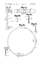
- FIG. 1 is an elevational view, partly in section, of a manhole casting and cover, chimney and cone, showing how the seal of the instant invention is positioned to seal the casting to the cone.
- FIG. 2 is a cross section of the cylindrical elastomeric seal of our invention.
- FIG. 3 consisting of FIGS. 3a-3c, shows the preferred structure of the retaining band used on the top sealing section.
- FIG. 3a is a top view of the band.
- FIG. 3b is a cross section of the retaining band at the point of overlap.
- FIG. 3c is a cross section of the band taken along the line C--C in FIG. 3a showing how the retaining band is slotted to receive and contain the securing band.
- FIG. 4 consisting of FIGS. 4a-4c, shows elements of the securing bands used to secure both sealing sections to the manhole and manhole casting.
- FIG. 4a is a side view of the ends of a band sealed by a crimped clamp.
- FIG. 4b is a side view of a clamp.
- FIG. 4c is a cross section of the band and clamp taken along the line C--C in FIG. 4a.
- FIG. 5 is an elevational view, partly in section, of the manhole casting cover, chimney and cone, showing an alternative embodiment of the seal of the present invention, which incorporates an extension skirt to increase the area covered by the seal.
- a preferred embodiment of the manhole chimney seal 12 is shown sealing a manhole casting 13, which receives a manhole cover 14, to the manhole cone 17, spanning adjusting rings 16 which constitute the manhole chimney 15.
- the seal functions to eliminate or substantially reduce the surface water infiltration over the area that it spans, whether the component parts are made of concrete, block or brick.
- the primary function of the invention is to seal between the casting 13 and the nearest section of chimney 15 or cone 17 that is sound and impermeable to water. This may involve spanning only a short distance below the casting 13, or may require a span of part or all of the chimney 15.
- the seal 12 consists of an extruded and spliced section of elastomeric material, the cross section for which is shown in FIG. 2. Suitable materials of construction are neoprene, polyisoprene rubber compound or other elastomeric rubber or plastic type material.
- the seal 12 has three primary sections, a first sealing section 19, a second sealing section 20 and a section intermediate those sections 21.
- the intermediate section 21 has corrugations 22.
- the corrugations 22 allow the seal to span a range of vertical distances, allow the seal 12 to be installed where there is vertical or horizontal displacement of the manhole casting 13 relative to the chimney 15 or the cone 17, and allow the seal 12 to accommodate displacement after installation, due to frost action, shifting ground conditions, traffic loadings and the like.
- the first sealing section 19 has an annular recess 23 on its inner side, giving the sealing section 19 a cross section with a vertical inner surface 24, a horizontal upper rim 25 and a horizontal lower rim 26. Dimensions of the first sealing section 19 are chosen so that the edge portion of the flange 27 of the casting 13 can be snugly fitted within the recess 23, so forming a tight seal against moisture.
- the vertical inner surface 24 may also have annular serrations 28 which deform under pressure so as to conform to irregularities which may exist in the flange surface 40, against which they are held, so creating an even tighter seal against water infiltration.
- the outer side 32 of the first sealing section 19 has an annular slot 29, located on the same level as the lower rim 26. Slot 29 is sized to receive the lower lip 30, shown in FIG. 3b, of a circular retaining band 31, FIG. 3a.
- the retaining band 31 has an inwardly facing squared-C cross section as shown in FIG. 3b.
- the retaining band 31 When the lower lip 30 is inserted into the annular slot 29, the retaining band 31 is positioned to receive the outer side 32 and a part of the top surface 33 of the first sealing section 19.
- the function of the retaining band 31 is to hold the first sealing section 19 in position relative to the flange 27, and to protect the first sealing section 19.
- the lower lip 30 on the retaining band 31 is removed at one end so as to overlap 34 with its other end, as shown in FIGS. 3a and 3b, thus completely encircling the first sealing section 19. An overlap of approximately three inches is suitable.
- Raised slotted sections 36 on the circumference of band 31 allow passage through them of a first securing band 37, which holds the retaining band 31 and the first sealing section 19 in place.
- the second sealing section 20 is to fit against the section of chimney 15 or cone 17 that is impermeable to water and is nearest to the casting 13.
- the preferred embodiment illustrates the sealing section 20 fitting against the surface 41 of the cone 17.
- the surface 42 of the second sealing section 20 may also have annular serrations 43 which deform under pressure to conform themselves to irregularities which may exist in the cone surface 41, to form a seal between surfaces 42 and 41 that is watertight.
- the outer surface 44 of the second sealing section 20 has an annular recess 45 of dimensions to accommodate a second securing band 38, which holds the second sealing section 20 in place.
- the securing bands 37, 38 are flat strips of material such as stainless steel. Referring to FIGS. 4a-4c, the ends 46, 47 of bands 37, 38 can be pulled together by a conventional ratchet-action tool until they overlap and bands 37, 38 tightly bind their respective associated sealing sections in place. The ends can then be sealed by crimping a clamp 48 at two or more crimping points 49 so as to mechanically lock the ends together.
- An extension skirt 50 is used to span a further vertical distance, between the second sealing section 20 and the manhole cone 17. This may be used in a situation where the lower section of the manhole chimney 15 is unsound and water permeable and the chimney 15 is too tall to be spanned by the intermediate section 21 alone.
- the second securing band 38 is shown holding both the upper portion 51 of the skirt and the second sealing section 20 in place against a surface of the chimney 15.
- a third securing band 52 holds the lower portion 53 of the skirt 50 against the surface 41 so as to form a watertight seal.
- This may be at the lower edge of the skirt, as shown, or may be at a higher level on the skirt, depending on the height of the chimney 15 that remains uncovered by the seal 12.
- Suitable materials for construction of the extension skirt are polyisoprene, neoprene or other rubber material, or a flexible vinyl or polyethylene material.
- a suitable thickness range for the material of the skirt is from a few thousandths of an inch to one-sixteenth of an inch.
- the skirt may be constructed of a continuous band of material, vulcanized or glued before installation, or may be constructed of multiple overlapping sections. The overlapped sections may be sealed by adhesive, or can be sealed by the pressure of the surrounding soil.
- Securing bands 37, 38, 52, retaining band 31, seal 12 and extension skirt 50 can also be manufactured to specific sizes to fit different sized manholes as specified in local codes.
- both the flange surface 40 and the cone surface 41 must be reasonably smooth and free of any loose material or excessive voids in order to create a tight seal with their respective sealing sections.
- both surfaces are brushed with a wire brush to remove loose material and to clean the surfaces. Any major flaws in the flange surface 40 can then be repaired by either grinding smooth or filling with mortar. If the cone surface 41 is very rough or irregular it can be smoothed with mortar.
- Joining material such as mortar is placed between the flange 27 and the chimney 15, leaving a space for the insertion of the lower rim 26 between the casting 13 and the chimney 15.
- both sealing sections 19, 20 are first lubricated with gasket lube to aid in sliding the seal 12 over the manhole assembly.
- the flange surface 40 and external surface of the chimney 15 or cone 17 may also be lubricated.
- the seal 12 is then installed by placing it over the manhole assembly so that it encircles the assembly, with the first sealing section 19 at the level of the flange 27 and the other sections of the seal 12 hanging downwards.
- the first sealing section 19 is fitted over the edge portion of the flange 27 so that the edge portion is inserted into the recess 23 and the inner surface 24 of the first sealing section 19 and the flange surface 40 are in contact.
- the lower lip 30 of the retaining band 31 is then inserted into the annular slot 29, so that the outer side 32 and a portion of the top surface 33 of the first sealing surface 19 are within the retaining band 31.
- the ends of the retaining band are overlapped 34 sufficiently for the retaining band 31 to closely encircle the first sealing section 19.
- the first securing band 37 is lubricated and threaded through the slots 36. If preferred this can be done before the retaining band 31 is put in place.
- the first securing band 37 is tightened and sealed as described above, to hold the retaining band 31 and the first sealing section 19 in place against the flange 27.
- the retaining band prevents any upward movement of the seal 12 during use and also serves to protect the first sealing section 19.
- the second securing band 38 is lubricated and is inserted in the annular recess 45 of the second sealing section 20. Downward pressure is applied to the second sealing section 20 to extend the intermediate section 21 until the second sealing section 20 is level with the already prepared surface 41 or a surface of the chimney 15. The second securing band 38 is then tightened and sealed, as described above, to hold the second sealing section 20 in place against the surface 41 or a surface of the chimney 15.
- each seal section and its respective associated manhole assembly surface is watertight, and as the seal 12 has been positioned so as to span all unsound and waterpermeable sections of the chimney 15 or cone 17, the result is to eliminate, or at least substantially reduce, infiltration of surface water into the manhole.
- the skirt 50 is lubricated and slid over the manhole assembly and positioned over the lower portion of the assembly, before the seal 12 is positioned at the top portion of the assembly.
- the second sealing section 20 is slid within the upper portion 51 of the skirt 50.
- the securing band 38 is lubricated and is inserted external to the upper portion 51 of the skirt, within the annular recess 45, so as to hold the upper portion 51 between the securing band 38 and the second sealing section 20.
- the securing band 38 is tightened as described above, to hold the upper portion 51 and the second sealing section 20 against a surface of the chimney 15.
- the second sealing section 20 is secured by the second securing band 38, and the upper portion 51 of the skirt 50 is positioned over the second securing band 38.
- An additional securing band is then placed to encircle the upper portion 51 of the skirt 50 and is tightened and sealed as is securing band 38, to hold the upper portion 51 in position.
- the skirt 50 hangs downwards from its secured upper portion 51 to cover the section of the chimney 15 that is not spanned by the seal 12.
- the third securing band 52 is placed around the skirt 50 at a level where the skirt 50 encircles the top of the manhole cone 17.
- the third securing band 52 is tightened as is the second securing band 38, to hold the lower portion 53 of the skirt 50 tightly against the surface 41 of the manhole cone 17. Any part of the skirt 50 hanging below the third securing band 52 can be trimmed or left hanging.
- the invention is a simply constructed and economically manufactured seal which overcomes problems presently existing in the subject matter to which the invention relates. While a specific preferred embodiment has been disclosed in detail, it is obvious to those skilled in the art that a differently shaped or configured sealing means can be utilized in a similar manner to achieve the objective of the invention. As an example, tightening or fastening of the securing rings can be achieved with other means well known to those skilled in the art. As further examples, the cross-sections of various components could differ from those shown and still perform as the invention is intended. It should be understood that the modifications and variations may be resorted to without departing from the spirit of the invention and that such modifications and variations are considered to be within the purview and scope of the present invention as defined by the following claims.
Landscapes
- Engineering & Computer Science (AREA)
- Environmental & Geological Engineering (AREA)
- Life Sciences & Earth Sciences (AREA)
- General Life Sciences & Earth Sciences (AREA)
- Mining & Mineral Resources (AREA)
- Paleontology (AREA)
- Civil Engineering (AREA)
- General Engineering & Computer Science (AREA)
- Structural Engineering (AREA)
- Underground Structures, Protecting, Testing And Restoring Foundations (AREA)
Priority Applications (2)
| Application Number | Priority Date | Filing Date | Title |
|---|---|---|---|
| US06/434,402 US4475845A (en) | 1982-10-14 | 1982-10-14 | External manhole chimney seal |
| CA000438550A CA1220659A (fr) | 1982-10-14 | 1983-10-06 | Etancheite sur assise de tampon d'un puits de visite |
Applications Claiming Priority (1)
| Application Number | Priority Date | Filing Date | Title |
|---|---|---|---|
| US06/434,402 US4475845A (en) | 1982-10-14 | 1982-10-14 | External manhole chimney seal |
Publications (1)
| Publication Number | Publication Date |
|---|---|
| US4475845A true US4475845A (en) | 1984-10-09 |
Family
ID=23724094
Family Applications (1)
| Application Number | Title | Priority Date | Filing Date |
|---|---|---|---|
| US06/434,402 Expired - Lifetime US4475845A (en) | 1982-10-14 | 1982-10-14 | External manhole chimney seal |
Country Status (2)
| Country | Link |
|---|---|
| US (1) | US4475845A (fr) |
| CA (1) | CA1220659A (fr) |
Cited By (39)
| Publication number | Priority date | Publication date | Assignee | Title |
|---|---|---|---|---|
| US4608787A (en) * | 1984-06-25 | 1986-09-02 | Carlson Franklin J | Manhole seal construction |
| US4659251A (en) * | 1985-09-23 | 1987-04-21 | Dover Corporation | Liquid spill container and method of making and installing same |
| US4709723A (en) * | 1986-07-17 | 1987-12-01 | Hancor, Inc. | Septic tank for alternative sewer systems |
| US4710050A (en) * | 1986-10-20 | 1987-12-01 | Pacific Scientific Co. | Modular metallic bellows assembly |
| US4712938A (en) * | 1986-01-13 | 1987-12-15 | Foster Wheeler Energy Corporation | Expansion seal assembly |
| US4759656A (en) * | 1986-09-29 | 1988-07-26 | Stephen K. Wilson | Construction of a manhole chimney |
| US4852891A (en) * | 1985-01-10 | 1989-08-01 | Toyoda Gosei Co., Ltd. | Plastic boots and method of manufacturing the same |
| US4917531A (en) * | 1989-06-08 | 1990-04-17 | Mcginnis Robert E | Temporary device for use with a manhole support during street repairs |
| US4957389A (en) * | 1989-09-05 | 1990-09-18 | Neathery David L | Method and apparatus for sealing manholes |
| WO1991016505A1 (fr) * | 1988-12-15 | 1991-10-31 | Neathery David L | Pieces encastrees dans un trou d'egout |
| US5078539A (en) * | 1991-03-13 | 1992-01-07 | Claing Jean Louis | Bendable raising structure for manhole cover with predetermined weak spot |
| DE4105835A1 (de) * | 1991-02-25 | 1992-09-03 | Bernhard Kessel | Abstuetzvorrichtung fuer schachtelemente |
| US5299884A (en) * | 1991-09-10 | 1994-04-05 | Poly-Tec Products, Inc. | Water lock method and apparatus |
| AT398215B (de) * | 1992-10-23 | 1994-10-25 | Goeschl Franz | Abdeckung für kanalschächte od. dgl. |
| US5362175A (en) * | 1992-07-28 | 1994-11-08 | Gaetan Begin | Manhole head assembly having a manhole top ring and method of use of the same |
| WO1996001929A1 (fr) * | 1994-07-11 | 1996-01-25 | Infi-Shield, Inc. | Procede et article permettant de rendre etanches des egouts ou des canalisations d'eau |
| US5511897A (en) * | 1994-07-11 | 1996-04-30 | Infi-Shield | Method of sealing a manhole riser and a catch basin and apparatus for same |
| DE4442273A1 (de) * | 1994-11-28 | 1996-05-30 | Passavant Werke | In das Erdreich einzubauendes Abscheidebecken aus Beton- oder Stahlbetonteilen |
| US5531485A (en) * | 1994-07-11 | 1996-07-02 | Infi-Shield Inc. | Method for sealing a pipe juncture |
| WO1997026415A1 (fr) * | 1996-01-22 | 1997-07-24 | Infi-Shield Inc. | Procede permettant de rendre etanches une colonne montante de regard de visite et un puisard et appareil correspondant |
| US5898044A (en) * | 1995-06-30 | 1999-04-27 | Nooren; Franciscus Petrus | Use of a preparation for insulation/sealing and coating purposes and method for sealing manhole covers |
| AT406277B (de) * | 1998-04-09 | 2000-03-27 | Rexeisen Yvonne | Vorrichtung zur lagerung von schachtabdeckungen u. dgl. |
| US6152455A (en) * | 1998-07-09 | 2000-11-28 | Npc, Inc. | Expandable band and locking mechanism |
| US6226929B1 (en) | 1995-10-31 | 2001-05-08 | Michael Gagas | Liquid infiltration prevention structures for preventing liquid infiltration manhole assemblies gate value sealing structures for preventing settling or shifting of key box bonnets and method for using said structures |
| AT409149B (de) * | 1998-12-17 | 2002-05-27 | Peter Hagen | Vorrichtung zur lagerung von schachtabdeckungen |
| US6641176B2 (en) | 2001-04-03 | 2003-11-04 | Ncp, Inc. | Wide clamping band for clamping a connector boot within a hole through a generally cylindrical wall |
| US20040021317A1 (en) * | 2002-07-31 | 2004-02-05 | Brockway Robert D. | Expandable band and locking mechanism |
| US20040232629A1 (en) * | 2002-03-28 | 2004-11-25 | Stefan Schonhoff | Sealing bellows with snap-on connection |
| US20050011573A1 (en) * | 2003-07-14 | 2005-01-20 | American Boa, Inc. | Flexible liner air gap pipe |
| US20060016132A1 (en) * | 2004-07-26 | 2006-01-26 | Belle Plaine Block And Tile, Inc. | Cover system for septic tank |
| US7150580B1 (en) * | 2005-08-24 | 2006-12-19 | Ess Paul H | Tapered manhole sealing band and method for use |
| US20070044841A1 (en) * | 2005-09-01 | 2007-03-01 | Adaptor, Inc. | Gate valve sealing structure |
| US20070116518A1 (en) * | 2005-11-18 | 2007-05-24 | Cretex Companies, Inc. | Self-sealing internal manhole chimney seal |
| USD546924S1 (en) | 2005-09-01 | 2007-07-17 | Adaptor, Inc. | Gate valve sealing structure |
| USD548309S1 (en) | 2005-09-01 | 2007-08-07 | Adaptor, Inc. | Gate valve sealing structure |
| US20080170908A1 (en) * | 2007-01-17 | 2008-07-17 | Ess Paul H | Angled manhole sealing band and method for use |
| USD577106S1 (en) | 2005-09-01 | 2008-09-16 | Adaptor, Inc. | Gate valve sealing structure |
| US20080296844A1 (en) * | 2007-05-31 | 2008-12-04 | Baker Hughes Incorporated | Downhole seal apparatus and method |
| USD583067S1 (en) | 2005-02-23 | 2008-12-16 | Adaptor, Inc. | Manhole assembly gate valve sealing structure |
Citations (14)
| Publication number | Priority date | Publication date | Assignee | Title |
|---|---|---|---|---|
| US1254641A (en) * | 1916-04-10 | 1918-01-22 | Frank Adam Electric Co | Floor-box. |
| US3294000A (en) * | 1964-03-30 | 1966-12-27 | Thurman A Pelsue | Manhole extension |
| US3490794A (en) * | 1968-06-28 | 1970-01-20 | Caterpillar Tractor Co | Exhaust manifold joints |
| US3516446A (en) * | 1968-01-26 | 1970-06-23 | Dresser Ind | Inside repair clamp |
| US3813116A (en) * | 1972-10-17 | 1974-05-28 | Interspace Corp | Coupling for plain end pipes |
| US3909412A (en) * | 1974-07-22 | 1975-09-30 | Johns Manville | Roof drain arrangement |
| US3958313A (en) * | 1974-06-05 | 1976-05-25 | Merchants National Bank Of Manchester | Method, apparatus and product for improved pipe-to-manhole sealing |
| US4059293A (en) * | 1975-12-01 | 1977-11-22 | Sipler Clarence L | Connector |
| GB2038976A (en) * | 1979-01-08 | 1980-07-30 | Alh Syst Ltd | Sleeves for joints in ducts |
| US4305679A (en) * | 1981-01-19 | 1981-12-15 | Modi Arvind O | Manhole sealing device |
| US4325572A (en) * | 1979-11-08 | 1982-04-20 | Arntyr Oscar Sven | Arrangement in rain-water drains or manholes |
| US4346922A (en) * | 1980-03-21 | 1982-08-31 | Hisao Ohtsuga | Device for preventing leakage at pipe joints |
| US4368893A (en) * | 1981-09-10 | 1983-01-18 | Stanley Gagas | Manhole infiltration disk and seal assembly |
| US4449715A (en) * | 1982-08-19 | 1984-05-22 | Michael Gagas | External manhole seal |
-
1982
- 1982-10-14 US US06/434,402 patent/US4475845A/en not_active Expired - Lifetime
-
1983
- 1983-10-06 CA CA000438550A patent/CA1220659A/fr not_active Expired
Patent Citations (14)
| Publication number | Priority date | Publication date | Assignee | Title |
|---|---|---|---|---|
| US1254641A (en) * | 1916-04-10 | 1918-01-22 | Frank Adam Electric Co | Floor-box. |
| US3294000A (en) * | 1964-03-30 | 1966-12-27 | Thurman A Pelsue | Manhole extension |
| US3516446A (en) * | 1968-01-26 | 1970-06-23 | Dresser Ind | Inside repair clamp |
| US3490794A (en) * | 1968-06-28 | 1970-01-20 | Caterpillar Tractor Co | Exhaust manifold joints |
| US3813116A (en) * | 1972-10-17 | 1974-05-28 | Interspace Corp | Coupling for plain end pipes |
| US3958313A (en) * | 1974-06-05 | 1976-05-25 | Merchants National Bank Of Manchester | Method, apparatus and product for improved pipe-to-manhole sealing |
| US3909412A (en) * | 1974-07-22 | 1975-09-30 | Johns Manville | Roof drain arrangement |
| US4059293A (en) * | 1975-12-01 | 1977-11-22 | Sipler Clarence L | Connector |
| GB2038976A (en) * | 1979-01-08 | 1980-07-30 | Alh Syst Ltd | Sleeves for joints in ducts |
| US4325572A (en) * | 1979-11-08 | 1982-04-20 | Arntyr Oscar Sven | Arrangement in rain-water drains or manholes |
| US4346922A (en) * | 1980-03-21 | 1982-08-31 | Hisao Ohtsuga | Device for preventing leakage at pipe joints |
| US4305679A (en) * | 1981-01-19 | 1981-12-15 | Modi Arvind O | Manhole sealing device |
| US4368893A (en) * | 1981-09-10 | 1983-01-18 | Stanley Gagas | Manhole infiltration disk and seal assembly |
| US4449715A (en) * | 1982-08-19 | 1984-05-22 | Michael Gagas | External manhole seal |
Non-Patent Citations (1)
| Title |
|---|
| State of Michigan, Dept. of State Highways, Supplemental Specification 8.08 (2), External Type Rubber Gaskets for Sealing Culvert and Sewer Pipe Joints. * |
Cited By (51)
| Publication number | Priority date | Publication date | Assignee | Title |
|---|---|---|---|---|
| US4608787A (en) * | 1984-06-25 | 1986-09-02 | Carlson Franklin J | Manhole seal construction |
| US4852891A (en) * | 1985-01-10 | 1989-08-01 | Toyoda Gosei Co., Ltd. | Plastic boots and method of manufacturing the same |
| US4659251A (en) * | 1985-09-23 | 1987-04-21 | Dover Corporation | Liquid spill container and method of making and installing same |
| US4712938A (en) * | 1986-01-13 | 1987-12-15 | Foster Wheeler Energy Corporation | Expansion seal assembly |
| US4709723A (en) * | 1986-07-17 | 1987-12-01 | Hancor, Inc. | Septic tank for alternative sewer systems |
| US4759656A (en) * | 1986-09-29 | 1988-07-26 | Stephen K. Wilson | Construction of a manhole chimney |
| US4710050A (en) * | 1986-10-20 | 1987-12-01 | Pacific Scientific Co. | Modular metallic bellows assembly |
| WO1991016505A1 (fr) * | 1988-12-15 | 1991-10-31 | Neathery David L | Pieces encastrees dans un trou d'egout |
| US4917531A (en) * | 1989-06-08 | 1990-04-17 | Mcginnis Robert E | Temporary device for use with a manhole support during street repairs |
| US4957389A (en) * | 1989-09-05 | 1990-09-18 | Neathery David L | Method and apparatus for sealing manholes |
| DE4105835A1 (de) * | 1991-02-25 | 1992-09-03 | Bernhard Kessel | Abstuetzvorrichtung fuer schachtelemente |
| US5078539A (en) * | 1991-03-13 | 1992-01-07 | Claing Jean Louis | Bendable raising structure for manhole cover with predetermined weak spot |
| US5299884A (en) * | 1991-09-10 | 1994-04-05 | Poly-Tec Products, Inc. | Water lock method and apparatus |
| US5362175A (en) * | 1992-07-28 | 1994-11-08 | Gaetan Begin | Manhole head assembly having a manhole top ring and method of use of the same |
| AT398215B (de) * | 1992-10-23 | 1994-10-25 | Goeschl Franz | Abdeckung für kanalschächte od. dgl. |
| US5613806A (en) * | 1994-07-11 | 1997-03-25 | Infi-Shield, Inc. | Sealing system for sewer and water applications |
| US5511897A (en) * | 1994-07-11 | 1996-04-30 | Infi-Shield | Method of sealing a manhole riser and a catch basin and apparatus for same |
| US5531485A (en) * | 1994-07-11 | 1996-07-02 | Infi-Shield Inc. | Method for sealing a pipe juncture |
| WO1996001929A1 (fr) * | 1994-07-11 | 1996-01-25 | Infi-Shield, Inc. | Procede et article permettant de rendre etanches des egouts ou des canalisations d'eau |
| US5800648A (en) * | 1994-07-11 | 1998-09-01 | Infi-Shield, Inc. | Exterior lining for catch basin or manhole |
| US5876533A (en) * | 1994-07-11 | 1999-03-02 | Infi-Shield, Inc. | Method of sealing a manhole riser and a catch basin and apparatus for same |
| DE4442273A1 (de) * | 1994-11-28 | 1996-05-30 | Passavant Werke | In das Erdreich einzubauendes Abscheidebecken aus Beton- oder Stahlbetonteilen |
| US5898044A (en) * | 1995-06-30 | 1999-04-27 | Nooren; Franciscus Petrus | Use of a preparation for insulation/sealing and coating purposes and method for sealing manhole covers |
| US6226929B1 (en) | 1995-10-31 | 2001-05-08 | Michael Gagas | Liquid infiltration prevention structures for preventing liquid infiltration manhole assemblies gate value sealing structures for preventing settling or shifting of key box bonnets and method for using said structures |
| US6449908B2 (en) | 1995-10-31 | 2002-09-17 | Michael Gagas | Gate valve box sealing |
| WO1997026415A1 (fr) * | 1996-01-22 | 1997-07-24 | Infi-Shield Inc. | Procede permettant de rendre etanches une colonne montante de regard de visite et un puisard et appareil correspondant |
| AT406277B (de) * | 1998-04-09 | 2000-03-27 | Rexeisen Yvonne | Vorrichtung zur lagerung von schachtabdeckungen u. dgl. |
| US6152455A (en) * | 1998-07-09 | 2000-11-28 | Npc, Inc. | Expandable band and locking mechanism |
| AT409149B (de) * | 1998-12-17 | 2002-05-27 | Peter Hagen | Vorrichtung zur lagerung von schachtabdeckungen |
| US6641176B2 (en) | 2001-04-03 | 2003-11-04 | Ncp, Inc. | Wide clamping band for clamping a connector boot within a hole through a generally cylindrical wall |
| US20040232629A1 (en) * | 2002-03-28 | 2004-11-25 | Stefan Schonhoff | Sealing bellows with snap-on connection |
| US7192214B2 (en) * | 2002-03-28 | 2007-03-20 | ZF Lemörder Metallwaren AG | Sealing bellows with snap-on connection |
| US6866301B2 (en) | 2002-07-31 | 2005-03-15 | Npc, Inc. | Expandable band and locking mechanism |
| US6953194B2 (en) | 2002-07-31 | 2005-10-11 | Npc, Inc. | Expandable band and locking mechanism |
| US20040021317A1 (en) * | 2002-07-31 | 2004-02-05 | Brockway Robert D. | Expandable band and locking mechanism |
| US20050011573A1 (en) * | 2003-07-14 | 2005-01-20 | American Boa, Inc. | Flexible liner air gap pipe |
| US7225587B2 (en) * | 2004-07-26 | 2007-06-05 | Belle Plaine Block And Tile, Inc. | Cover system for septic tank |
| US20060016132A1 (en) * | 2004-07-26 | 2006-01-26 | Belle Plaine Block And Tile, Inc. | Cover system for septic tank |
| USD583067S1 (en) | 2005-02-23 | 2008-12-16 | Adaptor, Inc. | Manhole assembly gate valve sealing structure |
| US7150580B1 (en) * | 2005-08-24 | 2006-12-19 | Ess Paul H | Tapered manhole sealing band and method for use |
| US20070044841A1 (en) * | 2005-09-01 | 2007-03-01 | Adaptor, Inc. | Gate valve sealing structure |
| USD546924S1 (en) | 2005-09-01 | 2007-07-17 | Adaptor, Inc. | Gate valve sealing structure |
| USD548309S1 (en) | 2005-09-01 | 2007-08-07 | Adaptor, Inc. | Gate valve sealing structure |
| US7703474B2 (en) | 2005-09-01 | 2010-04-27 | Adaptor, Inc. | Gate valve sealing structure |
| USD577106S1 (en) | 2005-09-01 | 2008-09-16 | Adaptor, Inc. | Gate valve sealing structure |
| US20070116518A1 (en) * | 2005-11-18 | 2007-05-24 | Cretex Companies, Inc. | Self-sealing internal manhole chimney seal |
| US20090074509A1 (en) * | 2007-01-17 | 2009-03-19 | Ssi Partnership Llc | Angled manhole sealing band and method for use |
| US20080170908A1 (en) * | 2007-01-17 | 2008-07-17 | Ess Paul H | Angled manhole sealing band and method for use |
| US7789586B2 (en) | 2007-01-17 | 2010-09-07 | Ssi Partnership, Llc | Angled manhole sealing band and method for use |
| US20080296844A1 (en) * | 2007-05-31 | 2008-12-04 | Baker Hughes Incorporated | Downhole seal apparatus and method |
| US7748467B2 (en) * | 2007-05-31 | 2010-07-06 | Baker Hughes Incorporated | Downhole seal apparatus and method |
Also Published As
| Publication number | Publication date |
|---|---|
| CA1220659A (fr) | 1987-04-21 |
Similar Documents
| Publication | Publication Date | Title |
|---|---|---|
| US4475845A (en) | External manhole chimney seal | |
| CA1211973A (fr) | Garniture d'etancheite entre elements d'un puits de visite | |
| US4957389A (en) | Method and apparatus for sealing manholes | |
| US6226929B1 (en) | Liquid infiltration prevention structures for preventing liquid infiltration manhole assemblies gate value sealing structures for preventing settling or shifting of key box bonnets and method for using said structures | |
| US4449715A (en) | External manhole seal | |
| US5303518A (en) | Lined manhole assembly and liner | |
| US5800648A (en) | Exterior lining for catch basin or manhole | |
| US4540310A (en) | Manhole riser and cooperating sleeve to provide a waterlock for manhole structures | |
| US4717036A (en) | Liquid tank spillage control system | |
| US4582449A (en) | Manhole sealing device | |
| US4325572A (en) | Arrangement in rain-water drains or manholes | |
| US4368893A (en) | Manhole infiltration disk and seal assembly | |
| US12410577B2 (en) | Securable temporary manhole or catch basin cover | |
| US6226928B1 (en) | Caustic fluid blocking member in the base of a manhole | |
| US5816746A (en) | Pile wrapper closure assembly and method of installing the same | |
| US5531485A (en) | Method for sealing a pipe juncture | |
| US9695569B1 (en) | Manhole cover sealing device | |
| US4557625A (en) | Internal sealing assembly | |
| US6122870A (en) | Stack ban | |
| US4608787A (en) | Manhole seal construction | |
| US5511897A (en) | Method of sealing a manhole riser and a catch basin and apparatus for same | |
| US4443282A (en) | Method of externally sealing sewage system joints against entry of ground water to the system | |
| US10731314B2 (en) | System for sealing a manhole riser ring assembly | |
| WO2004018787A1 (fr) | Dispositif de protection contre les inondations dans des trous d'homme et couvercles d'acces | |
| CA2153008A1 (fr) | Systeme d'etancheisation applicable aux ouvrages d'egout ou autres canalisations d'eau |
Legal Events
| Date | Code | Title | Description |
|---|---|---|---|
| AS | Assignment |
Owner name: CRETEX COMPANIES, INC.; 311 LOWELL ST., ELK RIVER Free format text: ASSIGNMENT OF ASSIGNORS INTEREST.;ASSIGNORS:ODILL, FRANK J.;ANDERSON, DAVID E.;REEL/FRAME:004061/0736;SIGNING DATES FROM 19821004 TO 19821007 |
|
| STCF | Information on status: patent grant |
Free format text: PATENTED CASE |
|
| FPAY | Fee payment |
Year of fee payment: 4 |
|
| FEPP | Fee payment procedure |
Free format text: PAYOR NUMBER ASSIGNED (ORIGINAL EVENT CODE: ASPN); ENTITY STATUS OF PATENT OWNER: LARGE ENTITY |
|
| FPAY | Fee payment |
Year of fee payment: 8 |
|
| FPAY | Fee payment |
Year of fee payment: 12 |