US4505103A - Chain joint for link chains - Google Patents
Chain joint for link chains Download PDFInfo
- Publication number
- US4505103A US4505103A US06/465,328 US46532883A US4505103A US 4505103 A US4505103 A US 4505103A US 46532883 A US46532883 A US 46532883A US 4505103 A US4505103 A US 4505103A
- Authority
- US
- United States
- Prior art keywords
- chain joint
- joint according
- teeth
- chain
- legs
- Prior art date
- Legal status (The legal status is an assumption and is not a legal conclusion. Google has not performed a legal analysis and makes no representation as to the accuracy of the status listed.)
- Expired - Lifetime
Links
Images


Classifications
-
- F—MECHANICAL ENGINEERING; LIGHTING; HEATING; WEAPONS; BLASTING
- F16—ENGINEERING ELEMENTS AND UNITS; GENERAL MEASURES FOR PRODUCING AND MAINTAINING EFFECTIVE FUNCTIONING OF MACHINES OR INSTALLATIONS; THERMAL INSULATION IN GENERAL
- F16G—BELTS, CABLES, OR ROPES, PREDOMINANTLY USED FOR DRIVING PURPOSES; CHAINS; FITTINGS PREDOMINANTLY USED THEREFOR
- F16G15/00—Chain couplings, Shackles; Chain joints; Chain links; Chain bushes
- F16G15/04—Quickly-detachable chain couplings; Shackles chain links with rapid junction means are classified according to the corresponding kind of chain
-
- F—MECHANICAL ENGINEERING; LIGHTING; HEATING; WEAPONS; BLASTING
- F16—ENGINEERING ELEMENTS AND UNITS; GENERAL MEASURES FOR PRODUCING AND MAINTAINING EFFECTIVE FUNCTIONING OF MACHINES OR INSTALLATIONS; THERMAL INSULATION IN GENERAL
- F16G—BELTS, CABLES, OR ROPES, PREDOMINANTLY USED FOR DRIVING PURPOSES; CHAINS; FITTINGS PREDOMINANTLY USED THEREFOR
- F16G15/00—Chain couplings, Shackles; Chain joints; Chain links; Chain bushes
- F16G15/02—Chain couplings, Shackles; Chain joints; Chain links; Chain bushes for fastening more or less permanently
Definitions
- the invention relates to a chain joint for link chains, having two identical, substantially U-shaped joint halves which are releasably connected to one another and each have an inner leg and an outer leg, the mutually facing sides of the inner and outer legs being connected to one another in the closed position of the joint by at least two in each case and at most four pairs of holding teeth in each case, and a supporting element for the joint halves being arranged between the mutually facing sides of the inner legs.
- this object is achieved when, in the case of two holding teeth per outer and inner leg, in each case the holding tooth, which is located most closely to the shackle base of the particular joint half, of the inner leg and the holding tooth, interacting with the former, of the outer leg and, in the case of three or four holding teeth per outer and inner leg, in each case the middle holding tooth or the two middle holding teeth of each leg are designed to be thicker than the holding teeth of the remaining pairs of holding teeth.
- those holding teeth of thicker design which are regularly located most closely to the centre of the chain joint possess a greater rigidity than the other holding teeth.
- the consequence of the increased rigidity is that the proportion of the forces to be transmitted by the thicker holding teeth increases as compared with the forces to be transmitted by the remaining holding teeth. This leads to a relief even of those holding teeth of the outer legs which are located most closely to the shackle base of the chain joint halves and reduces the risk of premature ruptures at the abovementioned critical points.
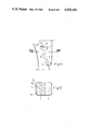
- FIG. 1 shows a plan view of a chain joint having two pairs of holding teeth
- FIG. 2 shows a section along the libe II--II in FIG. 1,
- FIG. 3 shows a detail of the chain joint according to FIGS. 1 and 2,
- FIG. 4 shows a plan view of a chain joint having three pairs of holding teeth
- FIG. 5 shows a side view of the chain joint according to FIG. 4,
- FIG. 6 shows a section along the line VI--VI in FIG. 4,
- FIG. 7 shows, partially in section, a first side view of a supporting and locking element consisting of two parts and forming a pre-assembled unit
- FIG. 8 shows a second side view, offset by 90° relative to the side view according to FIG. 7, of the supporting and locking element according to FIG. 7,
- FIG. 9 shows a view from below of the supporting and locking element according to FIGS. 7 and 8,
- FIG. 10 shows a further supporting and locking element consisting of two parts and forming a pre-assembled unit
- FIG. 11 shows a detail of the chain joint according to FIGS. 4-6
- FIG. 12 shows a section along the line XII--XII in FIG. 11,
- FIG. 13 shows a plan view of a chain joint having four pairs of holding teeth
- FIG. 14 shows a detail of the chain joint according to FIG. 13,
- FIG. 15 shows a plan view of a modified chain joint having three pairs of holding teeth
- FIG. 16 shows a plan view of a further chain joint having three pairs of holding teeth
- FIG. 17 shows a section along the line XVII--XVII in FIG. 16,
- FIG. 18 shows a plan view of a further chain joint having three pairs of holding teeth
- FIG. 19 shows a section along the line XIX--XIX in FIG. 18.
- 1 and 2 mark two joint halves which have the same shape and each of which has an outer leg 3 and an inner leg 4.
- the outer legs 3 have two holding teeth 5 and 6, and the inner legs 4 have two holding teeth 7 and 8.
- those holding teeth 7 of the inner leg 4 which are located most closely to the shackle base 9 of the joint halves 1 and 2 and the associated holding teeth 6 of the outer legs 3 are of thinner design than the other holding teeth 5 and 8. Therefore, the holding teeth 5 and 8 take up the main stress of the chain joint integrated into a chain strand.
- the mutually facing sides 10 of the inner legs 4 are provided with engagement recesses 11, in which an expansion element 12 can engage which is designed as a tensioning sleeve and which is held in the locking position, that is to say in the engagement recesses, by a bolt-shaped, that is to say cylindrical, supporting element 13 which supports the holding teeth 5 and 8 which absorb the main stress.
- the holding teeth 5 and 8 have the same tooth height h and the same tooth thickness s 1i and s 1a . Similar comments apply to the weaker holding teeth 6 and 7, but the tooth thickness s 2i and s 2a of the latter is smaller than the tooth thickness of the holding teeth 5 and 8, at the same tooth height.
- FIG. 2 shows that the sides, facing the inner legs 4, of the outer legs 3 have a concave shape and the sides, facing the outer leg 3, of the inner legs 4 have a convex shape.
- FIGS. 4-12 shows a chain joint which has proved to be particularly advantageous because of the use of three pairs of holding teeth.
- the joint halves are here also marked 1 and 2, and the inner and outer legs are marked 3 and 4.
- Each outer leg is provided with three holding teeth 14, 15 and 16, and each inner leg is provided with three holding teeth 17, 18 and 19.
- all the holding teeth have the same tooth height, but the tooth thickness of the holding teeth 15 and 18 is greater than the tooth thickness of the other holding teeth 16, 17 and 14, 19.
- a clearance a which fulfills the same purpose as in the first illustrative embodiment is present between the holding teeth 16 and 17.
- a special feature of the second chain joint is that, in the latter, a pre-assembled unit consisting of an expansion element 20 and a supporting element 21 which here also has a cylindrical shape is used for locking the chain joint.
- the expansion element 20 is clamped onto a collar 22 of the supporting element 21.
- the collar 22 is adjoined by an oblique surface 23.
- FIG. 12 shows that the surfaces 10 of the inner legs are provided on one side of the engagement recess 11 with a set-back surface 24. The distance between the surfaces 24 of the mutually opposite inner legs is slightly greater than the diameter of the pre-assembled expansion element 20 before its final expansion by the supporting element 21.
- the pre-assembled unit formed by the supporting element 21 and the expansion element 20 can, in the region of the surfaces 24, be easily transferred into the engagement recess 11, and specifically for such a distance that the end face 25 of the expansion element 20 comes to bear against the shoulder 26 of the engagement recess 11. As soon as this position has been reached, the supporting element 21 is knocked into the expansion element 20, and perfect locking and support are obtained.
- FIG. 10 shows a pre-assembled unit consisting of an expansion element 27 and a supporting element 28, the collar 29 of which has likewise a fully cylindrical shape.
- a chain joint having three pairs of holding teeth is particularly suitable in cases where the pitch t of the joint is greater than 3d and smaller than 4d, d being the diameter of the chain joint in the shackle zone or the diameter of the adjoining chain links not shown.
- the pitch t is defined as the maximum inner length of the chain joint as designated by the letter "t" in FIG. 4.
- FIG. 13 shows a chain joint consisting of two joint halves 1 and 2, the outer legs 3 of which each have four holding teeth 30, 31, 32 and 33 and the inner legs 4 of which are likewise each provided with four holding teeth 34, 35, 36 and 37.
- the holding teeth 31 and 32 of the outer legs 3 and the holding teeth 35 and 36 of the inner legs 4 are of a thicker design than the other holding teeth. The main stress is thus taken up by the pairs 31, 36 and 32, 35 of holding teeth. A clearance a is again present between the holding teeth 33 and 34.
- FIG. 15 shows a chain joint, in which the outer legs 3 and the inner legs 4 of each joint half 1 or 2 have again three holding teeth 38-40 or 41-43 respectively.
- the tips 44-46 of the holding teeth 38-40 are located on a circular arc.
- the apex of the circular arc here points in each case towards the centre of the chain joint.
- the holding teeth had substantially the same tooth height h, with different tooth thicknesses s.
- FIG. 16 an illustrative embodiment of a chain joint is shown, in which the heights of the holding teeth are different.
- the outer legs 4 of the chain joint according to FIG. 16 have holding teeth 47-49, and the inner legs 3 have holding teeth 50-52.
- the pairs of holding teeth 48, 51 are in this case also thicker than the pairs of holding teeth 47, 52 and 49, 50, which are more remote from the centre of the chain joint.
- the tooth height h 1 of the holding teeth 48 and 51 is greater than the tooth height h 2 of the holding teeth 49 and 50.
- the chain joint according to FIGS. 16 and 17 is locked by means of an expansion element 53 which is formed as a substantially U-shaped tensioning shackle with engagement legs 54 and 55.
- a supporting element 56 is arranged captively between the engagement legs 54 and 55 of the expansion element 53.
- the chain joint shown in FIGS. 18 and 19 corresponds largely to the chain joint according to FIGS. 4-6. It differs from the chain joint first described only by the type of locking chosen.
- the expansion element 57 is here also formed by a tensioning sleeve, securing is effected in this case by two supporting elements 58 and 59 which have the shape of wedges but which together again form a cylindrical support which is particularly advantageous for supporting the thicker holding teeth.
Landscapes
- Engineering & Computer Science (AREA)
- General Engineering & Computer Science (AREA)
- Mechanical Engineering (AREA)
- Devices For Conveying Motion By Means Of Endless Flexible Members (AREA)
- Clamps And Clips (AREA)
- Hooks, Suction Cups, And Attachment By Adhesive Means (AREA)
- Prostheses (AREA)
Applications Claiming Priority (2)
| Application Number | Priority Date | Filing Date | Title |
|---|---|---|---|
| DE3207629A DE3207629C2 (de) | 1982-02-26 | 1982-02-26 | Kettenschloß für Gliederketten |
| DE3207629 | 1982-02-26 |
Publications (1)
| Publication Number | Publication Date |
|---|---|
| US4505103A true US4505103A (en) | 1985-03-19 |
Family
ID=6157203
Family Applications (1)
| Application Number | Title | Priority Date | Filing Date |
|---|---|---|---|
| US06/465,328 Expired - Lifetime US4505103A (en) | 1982-02-26 | 1983-02-09 | Chain joint for link chains |
Country Status (5)
| Country | Link |
|---|---|
| US (1) | US4505103A (de) |
| AT (1) | AT389927B (de) |
| BR (1) | BR8300918A (de) |
| DE (1) | DE3207629C2 (de) |
| GB (1) | GB2116288B (de) |
Cited By (11)
| Publication number | Priority date | Publication date | Assignee | Title |
|---|---|---|---|---|
| US4706451A (en) * | 1985-02-13 | 1987-11-17 | Becker-Pronte Gmbh | Chain lock for round link chain strands particularly for use in mining |
| AU728159B2 (en) * | 1997-03-10 | 2001-01-04 | Rud Ketten Rieger & Dietz Gmbh U. Co. Kg | Chain Lock |
| US6216435B1 (en) * | 1999-03-19 | 2001-04-17 | Rud-Kettenfabrik Rieger & Dietz Gmbh U. Co. | Connecting chain link |
| US6220011B1 (en) * | 1999-03-19 | 2001-04-24 | Rud-Kettenfabrik Rieger & Dietz Gmbh U. Co. | Connecting chain link |
| US6223517B1 (en) * | 1999-03-19 | 2001-05-01 | Rud-Kettenfabrik Rieger & Dietz Gmbh U. Co. | Connecting chain link |
| WO2000031438A3 (de) * | 1998-11-20 | 2002-10-03 | Adam Udo Maschinenfabrik | Kettenflachschloss |
| US6679648B2 (en) * | 2000-12-16 | 2004-01-20 | J. D. Theile Gmbh & Co. Kg | Chain joint and center piece for such chain joint |
| US20100037585A1 (en) * | 2006-10-16 | 2010-02-18 | Thiele Gmbh & Co. Kg | Chain connecting link |
| US8756907B2 (en) * | 2011-08-30 | 2014-06-24 | Esco Corporation | Chain and coupling links |
| US20150226287A1 (en) * | 2012-09-11 | 2015-08-13 | Thiele Gmbh & Co. Kg | Chain connecting element with security crosspiece |
| US12234887B1 (en) * | 2020-05-20 | 2025-02-25 | The Crosby Group LLC | High fatigue life detachable connector |
Families Citing this family (10)
| Publication number | Priority date | Publication date | Assignee | Title |
|---|---|---|---|---|
| EP0183641A3 (de) * | 1984-11-29 | 1986-09-10 | RUD-Kettenfabrik Rieger & Dietz GmbH u. Co. | Kettenschloss |
| DE3444008C1 (de) * | 1984-11-29 | 1986-07-10 | Rud-Kettenfabrik Rieger & Dietz Gmbh U. Co, 7080 Aalen | Kettenschloß |
| DE4010399A1 (de) * | 1990-03-31 | 1991-10-02 | Becker Pruente Gmbh | Kettenschloss fuer rundgliederketten |
| DE4333261C1 (de) * | 1993-09-27 | 1994-10-27 | Rud Ketten Rieger & Dietz | Kettenschloß |
| GB2448315A (en) * | 2007-04-10 | 2008-10-15 | Fki Engineering Ltd | Connecting device having a deflecting formation |
| WO2011091810A1 (de) | 2010-01-26 | 2011-08-04 | Pewag Austria Gmbh | Kettenschloss für gliederketten |
| DE102010013474B4 (de) * | 2010-03-30 | 2015-08-13 | Thiele Gmbh & Co. Kg | Kettenschloss |
| DE202015101618U1 (de) * | 2015-03-31 | 2015-04-21 | Thiele Gmbh & Co. Kg | Kettenschloss mit Sicherungselement |
| US20180250197A1 (en) * | 2017-03-06 | 2018-09-06 | Your Solutions, Llc | Tethering device for a cup |
| DE102020100462B3 (de) * | 2020-01-10 | 2021-03-11 | Thiele Gmbh & Co Kg | Flachkettenschloss mit innenliegender Verzahnung |
Citations (9)
| Publication number | Priority date | Publication date | Assignee | Title |
|---|---|---|---|---|
| GB190702204A (en) * | 1907-01-29 | 1907-05-23 | Samuel James Britton | An Improved Coupling Link. |
| GB337085A (en) * | 1929-08-06 | 1930-10-30 | Humphrey George Taylor | Improvements in links and shackles for chain cables |
| DE694016C (de) * | 1937-04-22 | 1940-07-24 | Wilhelm Roeckel | Kettennotglied mit einem loesbaren Einsatzstueck in einem der Schenkel |
| US2353940A (en) * | 1943-05-14 | 1944-07-18 | Gilson C Staats | Detachable link |
| US2359535A (en) * | 1943-10-07 | 1944-10-03 | Gilson C Staats | Link |
| US2819586A (en) * | 1951-06-22 | 1958-01-14 | Pierre Henry St | Joiner link with two part bracing means having stop means thereon |
| DE1197291B (de) * | 1962-09-29 | 1965-07-22 | Carl Clarus Fa | Kettenverbindungsglied zur loesbaren Verbindung von Rundgliederketten, insbesondere fuer den Bergbau, z. B. fuer Foerderketten |
| GB1193647A (en) * | 1966-09-29 | 1970-06-03 | Coal Industry Patents Ltd | Improvements in Chain Connector Links. |
| DE1901367A1 (de) * | 1969-01-11 | 1970-08-06 | Becker Pruente Gmbh | Flachschloss fuer Gliederketten |
Family Cites Families (6)
| Publication number | Priority date | Publication date | Assignee | Title |
|---|---|---|---|---|
| DE190918C (de) * | ||||
| DE316681C (de) * | ||||
| US1980126A (en) * | 1933-06-23 | 1934-11-06 | Transue & Williams Steel Forgi | Separable link |
| DE631369C (de) * | 1934-12-04 | 1936-06-18 | Bochumer Ver Fuer Gussstahlfab | Zweiteiliges Kettenglied |
| DE1815409A1 (de) * | 1968-12-18 | 1970-06-25 | Hamborner Bergbau Ag | Kettenverbindungsglied |
| DE2200381C2 (de) * | 1972-01-05 | 1973-12-20 | Hans Dipl.-Ing. Dr. Rer. Pol. 4354 Datteln Reiter | Kettenverbindungsglied zum Herstellen einer lösbaren Verbindung von Rundgliederketten insbesondere für im Bergbau eingesetzte Förder- oder Zugketten |
-
1982
- 1982-02-26 DE DE3207629A patent/DE3207629C2/de not_active Expired
-
1983
- 1983-02-08 AT AT0043383A patent/AT389927B/de not_active IP Right Cessation
- 1983-02-09 US US06/465,328 patent/US4505103A/en not_active Expired - Lifetime
- 1983-02-17 GB GB08304361A patent/GB2116288B/en not_active Expired
- 1983-02-25 BR BR8300918A patent/BR8300918A/pt unknown
Patent Citations (9)
| Publication number | Priority date | Publication date | Assignee | Title |
|---|---|---|---|---|
| GB190702204A (en) * | 1907-01-29 | 1907-05-23 | Samuel James Britton | An Improved Coupling Link. |
| GB337085A (en) * | 1929-08-06 | 1930-10-30 | Humphrey George Taylor | Improvements in links and shackles for chain cables |
| DE694016C (de) * | 1937-04-22 | 1940-07-24 | Wilhelm Roeckel | Kettennotglied mit einem loesbaren Einsatzstueck in einem der Schenkel |
| US2353940A (en) * | 1943-05-14 | 1944-07-18 | Gilson C Staats | Detachable link |
| US2359535A (en) * | 1943-10-07 | 1944-10-03 | Gilson C Staats | Link |
| US2819586A (en) * | 1951-06-22 | 1958-01-14 | Pierre Henry St | Joiner link with two part bracing means having stop means thereon |
| DE1197291B (de) * | 1962-09-29 | 1965-07-22 | Carl Clarus Fa | Kettenverbindungsglied zur loesbaren Verbindung von Rundgliederketten, insbesondere fuer den Bergbau, z. B. fuer Foerderketten |
| GB1193647A (en) * | 1966-09-29 | 1970-06-03 | Coal Industry Patents Ltd | Improvements in Chain Connector Links. |
| DE1901367A1 (de) * | 1969-01-11 | 1970-08-06 | Becker Pruente Gmbh | Flachschloss fuer Gliederketten |
Cited By (17)
| Publication number | Priority date | Publication date | Assignee | Title |
|---|---|---|---|---|
| US4706451A (en) * | 1985-02-13 | 1987-11-17 | Becker-Pronte Gmbh | Chain lock for round link chain strands particularly for use in mining |
| AU728159B2 (en) * | 1997-03-10 | 2001-01-04 | Rud Ketten Rieger & Dietz Gmbh U. Co. Kg | Chain Lock |
| US6216434B1 (en) * | 1997-03-10 | 2001-04-17 | Rud-Kettenfabrik Rieger & Dietz Gmbh U. Co. | Chain joint |
| WO2000031438A3 (de) * | 1998-11-20 | 2002-10-03 | Adam Udo Maschinenfabrik | Kettenflachschloss |
| US6216435B1 (en) * | 1999-03-19 | 2001-04-17 | Rud-Kettenfabrik Rieger & Dietz Gmbh U. Co. | Connecting chain link |
| US6220011B1 (en) * | 1999-03-19 | 2001-04-24 | Rud-Kettenfabrik Rieger & Dietz Gmbh U. Co. | Connecting chain link |
| US6223517B1 (en) * | 1999-03-19 | 2001-05-01 | Rud-Kettenfabrik Rieger & Dietz Gmbh U. Co. | Connecting chain link |
| AU755921B2 (en) * | 1999-03-19 | 2003-01-02 | Rud-Kettenfabrik Rieger & Dietz Gmbh U. Co. | Connecting chain link |
| US6679648B2 (en) * | 2000-12-16 | 2004-01-20 | J. D. Theile Gmbh & Co. Kg | Chain joint and center piece for such chain joint |
| AU780779B2 (en) * | 2000-12-16 | 2005-04-14 | J D Theile Gmbh & Co Kg | Chain lock and middle piece for such chain lock |
| US20100037585A1 (en) * | 2006-10-16 | 2010-02-18 | Thiele Gmbh & Co. Kg | Chain connecting link |
| US8056315B2 (en) * | 2006-10-16 | 2011-11-15 | Thiele Gmbh & Co. Kg | Chain connecting link |
| US8756907B2 (en) * | 2011-08-30 | 2014-06-24 | Esco Corporation | Chain and coupling links |
| US20150226287A1 (en) * | 2012-09-11 | 2015-08-13 | Thiele Gmbh & Co. Kg | Chain connecting element with security crosspiece |
| US9169899B2 (en) * | 2012-09-11 | 2015-10-27 | Thiele Gmbh & Co. Kg | Chain connecting element with security crosspiece |
| RU2591776C1 (ru) * | 2012-09-11 | 2016-07-20 | ТИЛЕ ГМБХ унд КО.КГ | Соединительный элемент цепи с защитным распорным элементом |
| US12234887B1 (en) * | 2020-05-20 | 2025-02-25 | The Crosby Group LLC | High fatigue life detachable connector |
Also Published As
| Publication number | Publication date |
|---|---|
| ATA43383A (de) | 1989-07-15 |
| GB2116288A (en) | 1983-09-21 |
| AT389927B (de) | 1990-02-26 |
| DE3207629A1 (de) | 1983-09-15 |
| GB8304361D0 (en) | 1983-03-23 |
| GB2116288B (en) | 1986-03-19 |
| BR8300918A (pt) | 1983-11-16 |
| DE3207629C2 (de) | 1983-12-15 |
Similar Documents
| Publication | Publication Date | Title |
|---|---|---|
| US4505103A (en) | Chain joint for link chains | |
| CA1042638A (en) | Swaging dies | |
| CA2203634C (en) | Improvements in and relating to pipe connectors | |
| US3364767A (en) | Side-bar chain | |
| US4141599A (en) | Endless track | |
| US5046879A (en) | Perforated connecting disk for scaffolding elements | |
| CN110494674A (zh) | 活节链 | |
| US4615513A (en) | Flexible, force-transmitting element | |
| US4318637A (en) | Process and device for the assembly of voussoirs for tunnel linings | |
| US3744239A (en) | Chain link with extended wear surface | |
| US5590862A (en) | Device for adjusting the length of a support | |
| GB2190950A (en) | Pin and wedge clamps | |
| US6540617B2 (en) | Flange yoke for a universal joint and a universally jointed shaft | |
| CA1082264A (en) | Improvements in the construction of chainlinks of endless tracks for track vehicles | |
| US6196380B1 (en) | Apron-conveyor chain | |
| US5533938A (en) | Pocket chain wheel | |
| CA1147562A (en) | Chain link construction | |
| GB2126962A (en) | Anti-slip net for vehicle tyres | |
| US20050069379A1 (en) | Stopping means | |
| US5067776A (en) | Track adjustment wheel | |
| ES2333649T3 (es) | Dispositivo de posicionamiento para guias de ascensores. | |
| US4289059A (en) | Hook bolt adapter | |
| US5445571A (en) | Chain lock | |
| US4306605A (en) | Connector for chains | |
| US3582156A (en) | Connector for track-laying chains |
Legal Events
| Date | Code | Title | Description |
|---|---|---|---|
| AS | Assignment |
Owner name: RUD-KETTENFABRIK RIEGER & DIETZ GMBH, U. CO., 7080 Free format text: ASSIGNMENT OF ASSIGNORS INTEREST.;ASSIGNORS:DALFERTH, HANS H.;BAUER, JOHANNES;REEL/FRAME:004093/0876 Effective date: 19830124 |
|
| STCF | Information on status: patent grant |
Free format text: PATENTED CASE |
|
| FEPP | Fee payment procedure |
Free format text: PAYOR NUMBER ASSIGNED (ORIGINAL EVENT CODE: ASPN); ENTITY STATUS OF PATENT OWNER: LARGE ENTITY |
|
| FEPP | Fee payment procedure |
Free format text: PAYER NUMBER DE-ASSIGNED (ORIGINAL EVENT CODE: RMPN); ENTITY STATUS OF PATENT OWNER: LARGE ENTITY Free format text: PAYOR NUMBER ASSIGNED (ORIGINAL EVENT CODE: ASPN); ENTITY STATUS OF PATENT OWNER: LARGE ENTITY |
|
| FPAY | Fee payment |
Year of fee payment: 4 |
|
| FPAY | Fee payment |
Year of fee payment: 8 |
|
| FPAY | Fee payment |
Year of fee payment: 12 |