US4516254A - X-Ray lithographic apparatus - Google Patents
X-Ray lithographic apparatus Download PDFInfo
- Publication number
- US4516254A US4516254A US06/557,460 US55746083A US4516254A US 4516254 A US4516254 A US 4516254A US 55746083 A US55746083 A US 55746083A US 4516254 A US4516254 A US 4516254A
- Authority
- US
- United States
- Prior art keywords
- mask
- ray
- lithographic apparatus
- gastight chamber
- pressure
- Prior art date
- Legal status (The legal status is an assumption and is not a legal conclusion. Google has not performed a legal analysis and makes no representation as to the accuracy of the status listed.)
- Expired - Fee Related
Links
Images

Classifications
-
- G—PHYSICS
- G03—PHOTOGRAPHY; CINEMATOGRAPHY; ANALOGOUS TECHNIQUES USING WAVES OTHER THAN OPTICAL WAVES; ELECTROGRAPHY; HOLOGRAPHY
- G03F—PHOTOMECHANICAL PRODUCTION OF TEXTURED OR PATTERNED SURFACES, e.g. FOR PRINTING, FOR PROCESSING OF SEMICONDUCTOR DEVICES; MATERIALS THEREFOR; ORIGINALS THEREFOR; APPARATUS SPECIALLY ADAPTED THEREFOR
- G03F7/00—Photomechanical, e.g. photolithographic, production of textured or patterned surfaces, e.g. printing surfaces; Materials therefor, e.g. comprising photoresists; Apparatus specially adapted therefor
- G03F7/70—Microphotolithographic exposure; Apparatus therefor
- G03F7/708—Construction of apparatus, e.g. environment aspects, hygiene aspects or materials
- G03F7/70858—Environment aspects, e.g. pressure of beam-path gas, temperature
- G03F7/709—Vibration, e.g. vibration detection, compensation, suppression or isolation
-
- G—PHYSICS
- G03—PHOTOGRAPHY; CINEMATOGRAPHY; ANALOGOUS TECHNIQUES USING WAVES OTHER THAN OPTICAL WAVES; ELECTROGRAPHY; HOLOGRAPHY
- G03F—PHOTOMECHANICAL PRODUCTION OF TEXTURED OR PATTERNED SURFACES, e.g. FOR PRINTING, FOR PROCESSING OF SEMICONDUCTOR DEVICES; MATERIALS THEREFOR; ORIGINALS THEREFOR; APPARATUS SPECIALLY ADAPTED THEREFOR
- G03F7/00—Photomechanical, e.g. photolithographic, production of textured or patterned surfaces, e.g. printing surfaces; Materials therefor, e.g. comprising photoresists; Apparatus specially adapted therefor
- G03F7/70—Microphotolithographic exposure; Apparatus therefor
- G03F7/70216—Mask projection systems
- G03F7/7035—Proximity or contact printers
-
- G—PHYSICS
- G03—PHOTOGRAPHY; CINEMATOGRAPHY; ANALOGOUS TECHNIQUES USING WAVES OTHER THAN OPTICAL WAVES; ELECTROGRAPHY; HOLOGRAPHY
- G03F—PHOTOMECHANICAL PRODUCTION OF TEXTURED OR PATTERNED SURFACES, e.g. FOR PRINTING, FOR PROCESSING OF SEMICONDUCTOR DEVICES; MATERIALS THEREFOR; ORIGINALS THEREFOR; APPARATUS SPECIALLY ADAPTED THEREFOR
- G03F7/00—Photomechanical, e.g. photolithographic, production of textured or patterned surfaces, e.g. printing surfaces; Materials therefor, e.g. comprising photoresists; Apparatus specially adapted therefor
- G03F7/70—Microphotolithographic exposure; Apparatus therefor
- G03F7/708—Construction of apparatus, e.g. environment aspects, hygiene aspects or materials
- G03F7/70808—Construction details, e.g. housing, load-lock, seals or windows for passing light in or out of apparatus
-
- G—PHYSICS
- G03—PHOTOGRAPHY; CINEMATOGRAPHY; ANALOGOUS TECHNIQUES USING WAVES OTHER THAN OPTICAL WAVES; ELECTROGRAPHY; HOLOGRAPHY
- G03F—PHOTOMECHANICAL PRODUCTION OF TEXTURED OR PATTERNED SURFACES, e.g. FOR PRINTING, FOR PROCESSING OF SEMICONDUCTOR DEVICES; MATERIALS THEREFOR; ORIGINALS THEREFOR; APPARATUS SPECIALLY ADAPTED THEREFOR
- G03F7/00—Photomechanical, e.g. photolithographic, production of textured or patterned surfaces, e.g. printing surfaces; Materials therefor, e.g. comprising photoresists; Apparatus specially adapted therefor
- G03F7/70—Microphotolithographic exposure; Apparatus therefor
- G03F7/708—Construction of apparatus, e.g. environment aspects, hygiene aspects or materials
- G03F7/70858—Environment aspects, e.g. pressure of beam-path gas, temperature
- G03F7/70866—Environment aspects, e.g. pressure of beam-path gas, temperature of mask or workpiece
-
- H—ELECTRICITY
- H10—SEMICONDUCTOR DEVICES; ELECTRIC SOLID-STATE DEVICES NOT OTHERWISE PROVIDED FOR
- H10P—GENERIC PROCESSES OR APPARATUS FOR THE MANUFACTURE OR TREATMENT OF DEVICES COVERED BY CLASS H10
- H10P95/00—Generic processes or apparatus for manufacture or treatments not covered by the other groups of this subclass
Definitions
- the present invention relates to an X-ray lithographic apparatus.
- a wafer is exposed to radiation with both a mask and the wafer placed in a vacuum chamber in which an X-ray source is disposed. Since the X-ray flux does not come out of the vacuum chamber, it attenuates little, and the exposure efficiency is high. Since, however, the mask and the wafer must be handled and positioned in the vacuum chamber, the problems of low available percentage etc. have been involved.
- an X-ray source is placed in a vacuum chamber, and the wafer which is as proximate to a mask as ten ⁇ m--several tens ⁇ m is irradiated with the generated X-rays through a gastight chamber which is filled with helium gas or the like, easy to transmit the X-rays, under a pressure of approximately 1 atmosphere, as well as the mask which is mounted on one end of the gastight chamber. Accordingly, the mask must be so mounted that one surface confronts the gastight chamber filled with the helium gas or the like, while the other surface confronts the atmosphere.
- the mask since the X-rays attenuate greatly due to the helium gas or the like in the atmospheric exposure system, the mask is required to be as thin as possible. This has led to the occurrence of the problem that the mask vibrates on account of the pressure difference between the atmosphere and the gastight chamber filled with the helium gas or the like.
- a method is considered wherein the pressure difference between the atmosphere and the gastight chamber is detected and wherein the pressure of the helium gas or the like in the gastight space is controlled by a pressure regulator valve.
- a detection lag and the operation lag of the pressure regulator valve are involved.
- Another problem is the pressure regulation precision of the pressure regulator valve.
- An object of the present invention is to eliminate the disadvantages of the prior arts, and to provide an X-ray lithographic apparatus in which a pressure in the gastight space between an X-ray source and a mask is tuned to the atmospheric pressure so as to avoid the vibrations of the mask, whereby the blurring of a pattern edge to arise at exposure is prevented, and a pattern on the mask can be clearly transferred onto a wafer.
- a characterizing feature of the present invention is that a window of a member which is sufficiently softer than the mask is disposed between the gastight space and the atmosphere.
- the soft member caves in toward the gastight space before the mask, whereas when the atmospheric pressure has become lower than the pressure of the gastight space, the soft member becomes convex to tune the pressure of the gastight space and the atmospheric pressure and to prevent the vibrations of the mask. According to this method, even a minute pressure change can be prevented by employing a sufficiently soft member and forming the window near the mask.
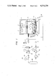
- FIG. 1 is an arrangement view showing an embodiment of an X-ray lithographic apparatus basedon the atmospheric exposure system according to the present invention
- FIG. 2 is a view showing a situation before exposure in the state in which a window made of a soft member according to the present invention is provided in the wall of a gastight chamber;
- FIG. 3 is a view showing the situation of the exposure in the state in which the window made of the soft member according to the present invention is provided in the wall of the gastight chamber;
- FIG. 4 is a view showing a section of a mask.
- an X-ray lithographic apparatus comprises an X-ray generator 4 which includes an electron gun 1, a target 2, and a window 3 made of beryllium for taking out a soft X-ray flux 2' emitted from the target 2; and a gastight chamber 10 which is connected with the X-ray generator 4, which includes a bellows 5, a holder 6 and a mask stage 7, and which is filled with helium gas under a pressure substantially equal to the atmospheric pressure.
- the mask stage 7 is so constructed as to be capable of adjusting, at least, its tilt relative to the holder 6, it holds a mask 8, and it has a window 9 for mounting a soft member.
- the apparatus comprises a wafer chuck 12 which holds a wafer 11 at a predetermined spacing of ten ⁇ m to several tens ⁇ m from the mask 8 by vacuum suction, corrective elements (for example, piezoelectric elements vertically expanded or contracted independently) 12" which correct the deformation of the wafer 11 through a partial thin sheet member in order to keep the predetermined spacing between the mask 8 and the wafer 11, and a ⁇ -stage 13, an X-stage 14 and a Y-stage 15 which support the wafer chuck 12 drawing the wafer 11 by vacuum suction, so as to be freely movable in rotational and horizontal directions.
- corrective elements for example, piezoelectric elements vertically expanded or contracted independently
- the upper surface of the thin sheet member is formed with a stria to which a hose 12' leading to a vacuum source is connected, so that protrusions may be arrayed partially and regularly. Also a space in which the corrective elements 12" are arranged is connected to the vacuum source.
- the holder 6 is provided with a tilt driving mechanism 27 in order that the mask stage 7 may equalize a distance from the target 2 to the mask 8.
- This tilt driving mechanism 27 is constructed of a driving motor 28, a reed screw 29 thereof, and a cam lever 30 adapted to turn to engage the mask stage 7.
- the mask stage 7 is suspended by springs 31.
- the X-ray generator 4 is supported so as to be finely movable vertically relative to the holder 6, and the fine adjustments of the lead screw etc. are disposed.
- the bellows 5 connects a certain part of the X-ray generator 4 and a certain part of the holder 6 in order to define the gastight chamber 10 and to permit the X-ray generator 4 to finely move vertically relative to the holder 6 as stated above.
- the details of these constituents are described in EPC Patent Application No. 82105096. 0 or U.S. patent application Ser. No. 387,206 now Pat. No. 4,475,223.
- the X-ray flux 2' emitted from the target 2 must be transmitted through the beryllium window 3, the gastight chamber 10 filled with the helium gas, and the mask 8.
- the provision of the gastight chamber 10 is intended to prevent the attenuation of the X-ray flux 2'.
- the transmission factor of the soft X-ray flux 2' for the beryllium window 3 is approximately 90%
- the transmission factor thereof for the gastight chamber 10 is approximately 96%
- the transmission factor thereof for the mask 8 is approximately 70%, so that the amount of the soft X-rays to reach the surface of the wafer 11 decreases to approximately 60%.
- the mask 8 is required to be more thinned to the end of increasing the amount of the soft X-rays 2' which reach the surface of the wafer 11.
- the window (about 50 mm--100 mm in diameter) made of the sufficiently soft member 9 is provided as shown in FIGS. 2 and 3.
- the soft member 9 is, for example, a rubber film or a polyvinyl chloride film approximately 5 ⁇ m thick.
- a shutoff valve 16 is closed and a shutoff valve 18 is opened, and the internal pressure of the gastight chamber 10 is reduced to 100 mmHg or so by a vacuum pump 20. Thereafter, a shutoff valve 17 is closed and the shutoff valve 16 is opened. Then, a change-over valve 22 is opened by a pressure switch 21 which is set at a pressure approximately 10 mmHg higher than the atmospheric pressure, and helium in a helium tank 26 flows into the gastight chamber 10 through a shutoff valve 24. When the internal pressure of the gastight chamber 10 has become higher than the atmospheric pressure in excess of 10 mmHg, the change-over valve 22 is closed by the pressure switch 21.
- the change-over valve 22 is opened by the pressure switch 21 again, to cause the helium to flow into the gastight chamber 10.
- the pressure in the gastight chamber 10 is held constant by repeating these operations, but minute pressure fluctuations on the order of 10 mmHg are inevitable. The pressure fluctuations, however, can be absorbed in such a way that the soft membrane member 9 which is highly sensitive is disposed in the wall of the gastight chamber 10 as described before.
- the mask 8 for the soft X-ray exposure is constructed as shown in FIG. 4.
- the illustrated example of the mask 8 is so formed that a polyimide film 34 which has a pattern 35 made of gold (Au) and which is 3-7 ⁇ m thick is stuck on a silicon substrate 33 which is provided with an opening of about 30 mm ⁇ 30 mm.
- the soft membrane member 9 When the soft membrane member 9 is disposed in proximity to the mask 8, the deformation of the mask 8 can be prevented more reliably. It is the best to provide the window with the soft membrane member stuck on the mask stage 7 as illustrated in the drawings.
Landscapes
- Health & Medical Sciences (AREA)
- Physics & Mathematics (AREA)
- General Physics & Mathematics (AREA)
- Engineering & Computer Science (AREA)
- Environmental & Geological Engineering (AREA)
- Epidemiology (AREA)
- Public Health (AREA)
- Life Sciences & Earth Sciences (AREA)
- Atmospheric Sciences (AREA)
- Toxicology (AREA)
- Exposure Of Semiconductors, Excluding Electron Or Ion Beam Exposure (AREA)
- Exposure And Positioning Against Photoresist Photosensitive Materials (AREA)
Applications Claiming Priority (2)
| Application Number | Priority Date | Filing Date | Title |
|---|---|---|---|
| JP57211407A JPS59101833A (ja) | 1982-12-03 | 1982-12-03 | X線露光装置 |
| JP57-211407 | 1982-12-03 |
Publications (1)
| Publication Number | Publication Date |
|---|---|
| US4516254A true US4516254A (en) | 1985-05-07 |
Family
ID=16605441
Family Applications (1)
| Application Number | Title | Priority Date | Filing Date |
|---|---|---|---|
| US06/557,460 Expired - Fee Related US4516254A (en) | 1982-12-03 | 1983-12-02 | X-Ray lithographic apparatus |
Country Status (3)
| Country | Link |
|---|---|
| US (1) | US4516254A (de) |
| EP (1) | EP0110414A3 (de) |
| JP (1) | JPS59101833A (de) |
Cited By (12)
| Publication number | Priority date | Publication date | Assignee | Title |
|---|---|---|---|---|
| US4648106A (en) * | 1984-11-21 | 1987-03-03 | Micronix Corporation | Gas control for X-ray lithographic system |
| US4748646A (en) * | 1986-03-18 | 1988-05-31 | Fujitsu Limited | X-ray lithography system |
| US4803713A (en) * | 1986-11-05 | 1989-02-07 | Nec Corporation | X-ray lighography system using synchrotron radiation |
| US4825453A (en) * | 1984-10-19 | 1989-04-25 | Hitachi, Ltd. | X-ray exposure apparatus |
| US5031199A (en) * | 1990-06-05 | 1991-07-09 | Wisconsin Alumni Research Foundation | X-ray lithography beamline method and apparatus |
| US5138643A (en) * | 1989-10-02 | 1992-08-11 | Canon Kabushiki Kaisha | Exposure apparatus |
| US5267292A (en) * | 1988-10-05 | 1993-11-30 | Canon Kabushiki Kaisha | X-ray exposure apparatus |
| US5371774A (en) * | 1993-06-24 | 1994-12-06 | Wisconsin Alumni Research Foundation | X-ray lithography beamline imaging system |
| US5390227A (en) * | 1988-09-09 | 1995-02-14 | Canon Kabushiki Kaisha | Exposure apparatus |
| US6313567B1 (en) * | 2000-04-10 | 2001-11-06 | Motorola, Inc. | Lithography chuck having piezoelectric elements, and method |
| US6364386B1 (en) * | 1999-10-27 | 2002-04-02 | Agilent Technologies, Inc. | Apparatus and method for handling an integrated circuit |
| USRE41232E1 (en) * | 2000-04-24 | 2010-04-20 | Nikon Corporation | Wafer positioner with planar motor and mag-lev fine stage |
Families Citing this family (2)
| Publication number | Priority date | Publication date | Assignee | Title |
|---|---|---|---|---|
| JPS61104619A (ja) * | 1984-10-29 | 1986-05-22 | Fujitsu Ltd | X線露光装置 |
| JPH0722112B2 (ja) * | 1987-07-30 | 1995-03-08 | キヤノン株式会社 | マスクホルダ並びにそれを用いたマスクの搬送方法 |
Citations (1)
| Publication number | Priority date | Publication date | Assignee | Title |
|---|---|---|---|---|
| US4403336A (en) * | 1981-04-13 | 1983-09-06 | Hitachi, Ltd. | X-Ray exposure apparatus |
-
1982
- 1982-12-03 JP JP57211407A patent/JPS59101833A/ja active Granted
-
1983
- 1983-12-01 EP EP83112086A patent/EP0110414A3/de not_active Ceased
- 1983-12-02 US US06/557,460 patent/US4516254A/en not_active Expired - Fee Related
Patent Citations (1)
| Publication number | Priority date | Publication date | Assignee | Title |
|---|---|---|---|---|
| US4403336A (en) * | 1981-04-13 | 1983-09-06 | Hitachi, Ltd. | X-Ray exposure apparatus |
Cited By (13)
| Publication number | Priority date | Publication date | Assignee | Title |
|---|---|---|---|---|
| US4825453A (en) * | 1984-10-19 | 1989-04-25 | Hitachi, Ltd. | X-ray exposure apparatus |
| US4648106A (en) * | 1984-11-21 | 1987-03-03 | Micronix Corporation | Gas control for X-ray lithographic system |
| US4748646A (en) * | 1986-03-18 | 1988-05-31 | Fujitsu Limited | X-ray lithography system |
| US4803713A (en) * | 1986-11-05 | 1989-02-07 | Nec Corporation | X-ray lighography system using synchrotron radiation |
| US5390227A (en) * | 1988-09-09 | 1995-02-14 | Canon Kabushiki Kaisha | Exposure apparatus |
| US5267292A (en) * | 1988-10-05 | 1993-11-30 | Canon Kabushiki Kaisha | X-ray exposure apparatus |
| US5138643A (en) * | 1989-10-02 | 1992-08-11 | Canon Kabushiki Kaisha | Exposure apparatus |
| US5031199A (en) * | 1990-06-05 | 1991-07-09 | Wisconsin Alumni Research Foundation | X-ray lithography beamline method and apparatus |
| US5371774A (en) * | 1993-06-24 | 1994-12-06 | Wisconsin Alumni Research Foundation | X-ray lithography beamline imaging system |
| US6364386B1 (en) * | 1999-10-27 | 2002-04-02 | Agilent Technologies, Inc. | Apparatus and method for handling an integrated circuit |
| US6394520B1 (en) | 1999-10-27 | 2002-05-28 | Agilent Technologies, Inc. | Apparatus and method for handling an integrated circuit |
| US6313567B1 (en) * | 2000-04-10 | 2001-11-06 | Motorola, Inc. | Lithography chuck having piezoelectric elements, and method |
| USRE41232E1 (en) * | 2000-04-24 | 2010-04-20 | Nikon Corporation | Wafer positioner with planar motor and mag-lev fine stage |
Also Published As
| Publication number | Publication date |
|---|---|
| JPS59101833A (ja) | 1984-06-12 |
| JPH0360170B2 (de) | 1991-09-12 |
| EP0110414A2 (de) | 1984-06-13 |
| EP0110414A3 (de) | 1986-03-26 |
Similar Documents
| Publication | Publication Date | Title |
|---|---|---|
| US4516254A (en) | X-Ray lithographic apparatus | |
| EP0867773B1 (de) | Trägerplattenvorrichtung und Verfahren zur Herstellung einer Schaltungsanordnung unter Verwendung derselben | |
| EP0676672B1 (de) | Behandlungsmethode und -vorrichtung für ein resistbeschichtetes Substrat | |
| KR100886399B1 (ko) | 반도체 장치의 제조방법 | |
| US5610683A (en) | Immersion type projection exposure apparatus | |
| EP4250342A2 (de) | Verbindungssystem und verbindungsverfahren | |
| US5164974A (en) | X-ray exposure apparatus | |
| US6809799B2 (en) | Processing system and device manufacturing method using the same | |
| JP3902583B2 (ja) | 可搬式密閉容器内部のパージシステムおよびパージ方法 | |
| JP2728898B2 (ja) | 露光装置 | |
| JP2001506427A (ja) | 制御されたガス供給源を具えるリソグラフ空気式支持装置 | |
| JP2005268268A (ja) | 電子ビーム露光装置 | |
| JP2766935B2 (ja) | X線露光装置 | |
| US4648106A (en) | Gas control for X-ray lithographic system | |
| JP2000349142A (ja) | 半導体ウェハ処理システムのための裏面ガス送出装置 | |
| US5347561A (en) | X-ray exposure apparatus and semiconductor-device manufacturing method | |
| JP2003059801A (ja) | 露光装置及び露光方法 | |
| JP2003332214A (ja) | 減圧装置、基板の制御方法、露光装置、半導体デバイスの製造方法 | |
| JPH11233426A (ja) | ガス純度管理方法およびガス純度管理システム、ならびに該ガス純度管理システムを適用した半導体露光装置およびデバイス製造方法 | |
| JPH10209036A (ja) | 露光方法および露光装置 | |
| JPH04110855A (ja) | たわみ補正機構付きマスク支持装置 | |
| JP2000021344A (ja) | ウエハ保持装置 | |
| JPH06295856A (ja) | He圧力コントロール方法及び露光装置用圧力コントロール装置 | |
| JP2791932B2 (ja) | X線露光装置 | |
| JP2009094368A (ja) | 原版搬送装置、露光装置およびデバイス製造方法 |
Legal Events
| Date | Code | Title | Description |
|---|---|---|---|
| AS | Assignment |
Owner name: HITACHI, LTD., 6, KANDA SURUGADAI 4-CHOME, CHIYODA Free format text: ASSIGNMENT OF ASSIGNORS INTEREST.;ASSIGNORS:KOMEYAMA, YOSHIHIRO;TANIGUCHI, MOTOYA;REEL/FRAME:004339/0497 Effective date: 19831117 Owner name: HITACHI, LTD.,JAPAN Free format text: ASSIGNMENT OF ASSIGNORS INTEREST;ASSIGNORS:KOMEYAMA, YOSHIHIRO;TANIGUCHI, MOTOYA;REEL/FRAME:004339/0497 Effective date: 19831117 |
|
| FPAY | Fee payment |
Year of fee payment: 4 |
|
| FEPP | Fee payment procedure |
Free format text: PAYOR NUMBER ASSIGNED (ORIGINAL EVENT CODE: ASPN); ENTITY STATUS OF PATENT OWNER: LARGE ENTITY |
|
| FPAY | Fee payment |
Year of fee payment: 8 |
|
| REMI | Maintenance fee reminder mailed | ||
| LAPS | Lapse for failure to pay maintenance fees | ||
| FP | Lapsed due to failure to pay maintenance fee |
Effective date: 19970507 |
|
| STCH | Information on status: patent discontinuation |
Free format text: PATENT EXPIRED DUE TO NONPAYMENT OF MAINTENANCE FEES UNDER 37 CFR 1.362 |