US4528754A - Self-propelled drawing device or tracing device - Google Patents
Self-propelled drawing device or tracing device Download PDFInfo
- Publication number
- US4528754A US4528754A US06/479,799 US47979983A US4528754A US 4528754 A US4528754 A US 4528754A US 47979983 A US47979983 A US 47979983A US 4528754 A US4528754 A US 4528754A
- Authority
- US
- United States
- Prior art keywords
- medium
- rotary members
- rotary
- chassis
- tracing
- Prior art date
- Legal status (The legal status is an assumption and is not a legal conclusion. Google has not performed a legal analysis and makes no representation as to the accuracy of the status listed.)
- Expired - Fee Related
Links
- 238000005304 joining Methods 0.000 claims abstract description 8
- 239000004020 conductor Substances 0.000 claims abstract description 7
- 239000000700 radioactive tracer Substances 0.000 claims description 9
- 238000000034 method Methods 0.000 claims description 6
- 230000011664 signaling Effects 0.000 claims description 2
- 239000013598 vector Substances 0.000 description 5
- 235000004443 Ricinus communis Nutrition 0.000 description 4
- 230000001186 cumulative effect Effects 0.000 description 4
- 238000004519 manufacturing process Methods 0.000 description 3
- 239000000463 material Substances 0.000 description 3
- 239000004033 plastic Substances 0.000 description 3
- 229920003023 plastic Polymers 0.000 description 3
- 238000004364 calculation method Methods 0.000 description 2
- 229910052751 metal Inorganic materials 0.000 description 2
- 239000002184 metal Substances 0.000 description 2
- 230000005693 optoelectronics Effects 0.000 description 2
- 230000002093 peripheral effect Effects 0.000 description 2
- 238000005096 rolling process Methods 0.000 description 2
- 240000000528 Ricinus communis Species 0.000 description 1
- 229910000971 Silver steel Inorganic materials 0.000 description 1
- 229910000831 Steel Inorganic materials 0.000 description 1
- 230000001133 acceleration Effects 0.000 description 1
- 125000000218 acetic acid group Chemical group C(C)(=O)* 0.000 description 1
- 238000006243 chemical reaction Methods 0.000 description 1
- 239000003086 colorant Substances 0.000 description 1
- 238000006073 displacement reaction Methods 0.000 description 1
- 230000000694 effects Effects 0.000 description 1
- 238000004146 energy storage Methods 0.000 description 1
- 230000006870 function Effects 0.000 description 1
- 230000014509 gene expression Effects 0.000 description 1
- 238000005286 illumination Methods 0.000 description 1
- 239000011159 matrix material Substances 0.000 description 1
- 239000002991 molded plastic Substances 0.000 description 1
- 230000003287 optical effect Effects 0.000 description 1
- 238000003825 pressing Methods 0.000 description 1
- 230000000717 retained effect Effects 0.000 description 1
- 239000010959 steel Substances 0.000 description 1
- 238000003860 storage Methods 0.000 description 1
- 210000003954 umbilical cord Anatomy 0.000 description 1
Images


Classifications
-
- G—PHYSICS
- G01—MEASURING; TESTING
- G01D—MEASURING NOT SPECIALLY ADAPTED FOR A SPECIFIC VARIABLE; ARRANGEMENTS FOR MEASURING TWO OR MORE VARIABLES NOT COVERED IN A SINGLE OTHER SUBCLASS; TARIFF METERING APPARATUS; MEASURING OR TESTING NOT OTHERWISE PROVIDED FOR
- G01D9/00—Recording measured values
- G01D9/40—Producing one or more recordings, each recording being produced by controlling either the recording element, e.g. stylus or the recording medium, e.g. paper roll, in accordance with two or more variables
-
- B—PERFORMING OPERATIONS; TRANSPORTING
- B43—WRITING OR DRAWING IMPLEMENTS; BUREAU ACCESSORIES
- B43L—ARTICLES FOR WRITING OR DRAWING UPON; WRITING OR DRAWING AIDS; ACCESSORIES FOR WRITING OR DRAWING
- B43L13/00—Drawing instruments, or writing or drawing appliances or accessories not otherwise provided for
- B43L13/02—Draughting machines or drawing devices for keeping parallelism
- B43L13/022—Draughting machines or drawing devices for keeping parallelism automatic
- B43L13/024—Drawing heads therefor
-
- B—PERFORMING OPERATIONS; TRANSPORTING
- B43—WRITING OR DRAWING IMPLEMENTS; BUREAU ACCESSORIES
- B43L—ARTICLES FOR WRITING OR DRAWING UPON; WRITING OR DRAWING AIDS; ACCESSORIES FOR WRITING OR DRAWING
- B43L13/00—Drawing instruments, or writing or drawing appliances or accessories not otherwise provided for
- B43L13/02—Draughting machines or drawing devices for keeping parallelism
- B43L13/022—Draughting machines or drawing devices for keeping parallelism automatic
- B43L13/026—Draughting machines or drawing devices for keeping parallelism automatic for writing characters or symbols
Definitions
- the present invention relates to a self-propelled drawing device or a tracing device which can be for example an output peripheral for a desk top computer.
- the drawing device can be referred to as an "X-Y plotter". During the drawing, it should be able to access substantially all of the drawing medium.
- the drawing device draws a desired trajectory or locus or suitable approximation thereto as defined by computing or calculating means.
- the data to be plotted is held as a series of vectors in computer memory. Each vector is converted to the necessary movements required to reproduce the data on the drawing medium.
- the conversion calculations from vectors to movements may be carried out in the desk top computer, or in the drawing device or in a secondary device which interfaces between the two.
- the tracing device works in reverse in that it is made to follow a line by manual propulsion, and signal the trajectory or locus of the line or a suitable approximation thereto to computing or storage means.
- Both the drawing device and the tracing device act as a drafting peripheral in the form of a locus-tracking device in that the drawing device tracks a locus in order to draw a line and the tracing devices tracks a locus on a planar medium.
- One aspect of the invention relates to a self-propelled drawing device for moving upon a drawing medium, the drawing device comprising two independently-driven rotary members for rolling on the drawing medium and driving the drawing device, the axes of the rotary members being fixed relative to the drawing device, whereby the path followed by the drawing device is determined by the individual rotations of the rotary members, and at least one writing means which will mark the drawing medium.
- the invention also relates to a tracing device comprising two independently-rotatable rotary members for rolling on the medium, the axes of the rotary members being fixed relative to the tracing device, whereby the individual rotations of the rotary members correspond to the path followed by the tracing device, means connected to the rotary members for sensing and signalling the individual rotations of the rotary members, and at least one tracing means which can be moved by manual propulsion of the tracing device.
- the tracing means may be for instance a digitizing sight or lightspot, as is well known.
- the tracing means need not necessarily be traced along a line, but could for instance be laid over a point of interest whose coordinates are communicated to or calculated or inferred by suitable electronic apparatus.
- U.S. Pat. No. 3,726,019 describes a drawing device having a steerable driving wheel and two idle wheels.
- the writing means can be off the common axis of the idle wheels.
- the movement of the device is restricted. To draw a straight line, the device must first position itself with the axis of the idle wheels at right angles to the line.
- WO 81/03561 describes a drawing device (FIG. 2) in which there are two independently-driven, coaxial driving wheels and two castors.
- the writing means is on the common axis of the driving wheels. This device lacks one degree of freedom in that in order to draw a straight line, it must first position itself with the axis of the driving wheels at right angles to the line.
- GB 2 015 755 describes a complex device (FIGS. 7 and 8).
- U.S. Pat. No. 3,726,019, and WO 81/03561 and to a certain extent in GB 2 015 755, if a sharp curve is to be drawn, considerable activity is required for steering, out of proportion to the actual length of line being drawn; for instance annotation with characters or other small symbols would be slow.
- the rotary members are independent and have their axes fixed relative to the drawing device or tracing device--in the case of the drawing device the rotary members are independently driven whilst in the case of the tracing device, the individual rotations of the rotary membrs correspond to the path followed by the tracing device.
- the writing means of the drawing device is arranged to mark the drawing medium at a point which is not on the imaginary line joining the points of contact of the rotary members with the drawing medium, or the tracing means is arranged such at any moment it traces at a point which is not on the imaginary line joining the points of contact of the rotary members with the medium.
- the device of the invention can be of small size and have low inertia and mass.
- the writing means has an extra degree of freedom.
- the rotary members are referred to for convenience herein as “driving wheels”, though it will be understood they could for instance be shaft ends. They do not slip either sideways or tangentially, but only roll in the direction at right angles to their axes.
- driving wheels By controlling the relative velocities of the driving wheels, the driving wheels and therefore the whole drawing device can be made to rotate any amount about any chosen point on said imaginary line--no complex steering mechanism is required.
- the writing means which is off said imaginary line, may be instantaneously moved in any direction and therefore incrementally made to follow or reconstruct any given locus at constant speed along the locus, irrespective of the orientation of the drawing device provided it is not at the edge of the drawing medium.
- straight lines can be drawn without any pre-positioning of the device, whatever the orientation of the device. This improves accuracy and also reduces "dead" time. Small radius curves can be drawn at the same speed as straight lines so that the device can be suitable for writing characters or symbols.
- the device can, with some sacrifice of net line speed, be arranged to plot near the edge of the paper while the device itself does not leave the paper.
- the drawing device need have only three moving parts, namely two motors with the respective driving wheels and a pen lift or other mechanism for preventing the writing means marking the drawing medium.
- the writing means can be positioned arbitrarily on the device. There can be multiple writing means on the device, in which case it is easier if they are all the same distance from said imaginary line.
- the different writing means may be for instance different writing tips to suit different drawing media or may have different attributes, such as colour or line-width.
- any writing means could be used, for instance a felt-tipped pen or a dot-matrix needle printing head.
- the writing means may be fixed, or an arrangement may be included for tilting the device about the driving wheels to bring the writing means in contact with the drawing medium, or there may be lifts for the writing means. If desired, there may be a magazine or rotating carousel for changing the writing means at the same position. If the drawing means can be withdrawn from the drawing medium, an idle support, e.g. a castor or low-friction sliding shoe, can be provided for giving proper support to the device.
- an idle support e.g. a castor or low-friction sliding shoe
- the driving wheels need not be of precisely the same effective diameter. Two devices can be used simultaneously or concurrently to produce different parts of the same drawing or different colours.
- the relative movements of the driving wheels can be calculated and/or controlled by suitable electronic apparatus such as a microprocessor or microcomputer accommodated on the device itself or communicating with it by a flexible connection or remote control signal.
- the remote control signal could be an infra-red signal.
- an energy storage means normally a battery moving with the device, or for instance a flexible connection for the power.
- Another aspect of the invention relates to a self-propelled drawing device for moving upon a drawing medium connected to a stationary control device which controls the movement of the drawing device by means of flexible conductors connected to the drawing device and to the control device.
- the invention also relates to a tracing device for being moved upon a medium and arranged to give signals corresponding to the movement of the tracing device, connected to a stationary receiving device for receiving said signals by means of flexible conductors connected to the tracing device and to the receiving device.
- the flexible conductors are in the form of a ribbon which is connected to the drawing or tracing device and to the control or receiving decive with its width vertical.
- the ribbon (which may alternatively be called a tape) can transmit all power and control signals.
- the ribbon stands on edge; it is arranged never to be straight and will always support itself vertically assuming a serpentine configuration as shown in FIG. 1; unlike other umbilical cords, the ribbon is extremely supple in the plane of the paper, and can never go under the wheels.
- the ribbon can tend to roll up and apply light tension to itself, excess ribbon being accomodated in a circular housing in said control or receiving device--in this version the ribbon need not touch the drawing medium.
- the drawing device can be programmed so that it does not wind the ribbon around itself.
- the ribbon can be connected to the drawing or tracing device and to the control or receiving device slightly above the level of the drawing medium, for instance 2 to 3 mm, to avoid manufacturing tolerances causing the ribbon to project below and support some of the weight of the drawing or tracing device. With suitable arrangement, problems such as picking up the corner of the drawing medium can be avoided.
- FIG. 1 is a schematic view of a stand-alone plotter and associated equipment
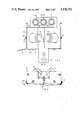
- FIG. 2 is a plan of a plotter head in accordance with the invention.
- FIG. 3 is a rear end view of the plotter head of FIG. 2;
- FIG. 4 is a front end view of the plotter head of FIG. 2, partly in section along the line IV--IV in FIG. 2;
- FIG. 5 is a section along the line V--V in FIG. 2;
- FIGS. 6 and 7 illustrate the geometry of the plotter head
- FIGS. 8 to 10 correspond generally to FIGS. 2, 3 and 5, but show a different plotter head
- FIG. 11 corresponds to FIG. 5 but shows a tracer in accordance with the invention.
- FIG. 1 is schematic, and shows a planar drawing medium 1, a plotter head 2 or 3, a slack umbilical ribbon 4, shown as being disposed vertically on edge and assuming a serpentine configuration a control unit or microprocessor 5, a power unit 6, and a desk-top microcomputer 7 stationary digital electronic data means with keyboard and VDU.
- the microprocessor 5 can be an 8-bit single chip microprocessor such as the Motorola 6801 or Hitachi 6301.
- the microcomputer can be an Apple II.
- the microprocessor 5 provides a standard interface and accepts a standard, simple set of commands. Suitable commands are known, such as those published for the Hewlett-Packard GL plotter language or any other suitable set of vector commands.
- the plotter head 2 shown in FIGS. 2 to 5 is an experimental head, having a bolted-together metal chassis 11. It has two independently-driven rotary members or propelling in the form of driving wheels 12 supported by the output shafts of electric stepper motors or D.C. motors 13 provided with opto-electronic encoder discs.
- the axes of the wheels 12 are fixed in relation to the chassis 11, being inclined at 45° to the horizontal, lying in a substantially vertical plane, and intersecting above the level of the centres of the wheels 12.
- the axes of the wheels 12 preferably intersect above (rather than below) the level of the centres of the wheels 12, as this enables the direct drive motors 13 to be positioned inboard of the wheels 12.
- the wheels 12 could be made for instance of grit-blasted silver steel (hard steel) though any hard-wearing material which has a high coefficient of friction would be suitable.
- the acceleration expected is less than 1 g, probably about 0.1 g.
- the wheels 12 should have a knife edge, but knife edges cause rutting and a slight radius is provided.
- the chassis 11 carries an idle support in the form of a castor wheel 14 which is arranged to swing about a vertical axis in a conventional manner, thereby providing three-point support for the chassis 11.
- the chassis 11 also carries a counterweight 15 which is adjustable.
- the chassis 11 also carries holders 16 made of plastics material for holding writing or reproducing means in the form of felt-tipped pens 17.
- the pens 17 are on the other side of the wheels 12 to the castor wheel 14. In this experimental version, no pen lift is provided.
- the pens 17 are arranged to move up and down in the holders 16 under their own weight, therefore following any undulations in the drawing medium 1.
- the ink should dry sufficiently well to prevent pick-up.
- the chassis 11 also carries opto-reflective sensors 18.
- the ribbon 4 is secured by a clamp 19 to the chassis 11 so that it is connected to the plotter head with its width lying in a vertical plane so that the ribbon stands on its edge and supports itself vertically; the ribbon 4 is connected to the microprocessor 5 by another clamp 20 so that its plane is vertical (see FIG. 1).
- the motors 13 can be Portescap 23L motors with a 100 lines encoder
- the pens 17 can be HP type plotter pens, e.g. catalogue numbers 5060 to 6818.
- the sensors 18 can be Honeywell SPX1397 sensors and the ribbon 4 can be a 16 conductor ribbon, 20 mm high.
- the movement of the plotter head 2 is modelled by a set of three iterative equations such that for a sequence of pen positions spaced ds apart along a line to be drawn.
- the necessary wheel movements are determined and used to drive the plotter.
- the head 2 tracks a locus, interconverting digital electronic data and two-dimensional positional data on the drawing medium 1.
- the plotter can be programmed to prevent the wheels 12, 14 leaving the drawing medium 1 when plotting close to the edge.
- the wheels 12 and writing point 17 are defined as follows:
- Each wheel 12 has a point contact L or R with the drawing medium 1 (see FIG. 6).
- the line from L to R is defined as the wheel axis and has an orientation ⁇ p with reference to an arbitrary reference.
- the writing point P is a distance w from the wheel axis.
- a is initial the angle between the vector (the increment of the line) to be plotted and the wheel axis LR, expressed in radians;
- KL, KR are the gains associated with each wheel, i.e. the distance moved per integer unit of PL, PR, expressed as length (e.g. in mm) per unit.
- R is radius of curvature of arc being drawn.
- sine and cosine functions can be implemented efficently using table interpolation.
- Self-calibration can be used to establish or eliminate variation in parameters associated with the device, such as position, orientation and dimensional tolerance associated with the driving wheels 12 and pens 17, and slippage between the driving wheels 12 and the drawing medium 1.
- parameters associated with the device such as position, orientation and dimensional tolerance associated with the driving wheels 12 and pens 17, and slippage between the driving wheels 12 and the drawing medium 1.
- KL, KR and w will cause cumulative errors if they are inaccurate.
- ⁇ w/ds is chosen as an exact power of 2
- errors in w merely lead to scaling errors and not geometric distortion. Calibration is therefore only required for the values of (KL/ds) and (KR/ds), which are dimensionless ratios.
- the plotter head 2 is signalled to execute a turn through a specific angle, and the error is measured and used to correct the signal.
- the whole operation can be carried out by pressing one command button, and the signals and the correction can be generated in the microprocessor 5 (functioning as part of "calibrating means").
- the edge of the drawing medium 1 can be chosen as a datum line--the plotter head 2 can be signalled to move away from the edge before carrying out the turn if the turn is to be through a large angle such as 360° (or a multiple thereof for greater accuracy); the plotter head 2 can be withdrawn from the datum line for instance by turning both wheels 12 or by just turning one wheel 12 and then rotating the plotter head 2 about a, or the other, wheel 12.
- two edges of the drawing medium at 90° could be used, providing they are sufficiently accurately defined.
- the sensors 18 are outboard of the wheels 12, and optical (or other) marks are placed on the edge of the drawing medium or for instance on a rule, the plotter head 2 could be arranged to start with its wheel axes parallel to the edge, turn through 90°, run along the edge and read a portion of the marks.
- the microprocessor 5 causes the plotter head 2 to carry out the following calibration sequence:
- the sensors 18 are brought within an initial step distance (say about 3 mm) from the edge and this distance is then reduced to 1 machine step.
- the reading of the two sensors 18 will define one of four appropriate directions (backwards, forward, left or right) for the selected pen 17 to move in order to bring the sensors 18 closer to the edge.
- a suitable routine is:
- step size is halved to give successive approximation
- the microcomputer 5 can derive either the total number of steps to execute respective 360° rotations of the plotter head 2 with each wheel 12, or the net rotation of the plotter head 2 for a given number of steps.
- any means can be used to establish an initial or datum position, for instance an obstacle if the wheels 12 do not slip significantly on stalling.
- the plotter head 3 of FIGS. 8 to 10 is in principle very similar to that of FIGS. 2 to 5, and the same references are used for identical or similar parts.
- the plotter head 3 has a moulded plastic or die cast metal chassis 21 which is suitable for mass production.
- Encoder discs 22 and associated opto-electronic readers 23 are indicated in FIGS. 8 and 9, the readers 23 being mounted directly on a printed circuit board 24.
- the motors 13 are supported by a bearing system indicated conventionally in FIG. 9 and by a screwed-on plate 25.
- each electromagnet 26 is associated with an armature 27 which is fixed to the end of a double lever 28 made of a suitable plastics material such as acetyl.
- the lever 28 has an integrally-moulded pivot pin 29 which is a snap fitting in the chassis 21.
- the long arm of the lever 28 is of inverted T-section (see FIG. 9), but the flanges are divided from the centre web by slits 30 (see FIG. 8).
- the tracer head or tracing device 41 is constructively strictly analagous to the plotter head 2 (or 3), and need not be described in detail.
- Conventional counters 42 are connected to the wheels 12 to signal their rotation.
- the microprocessor 5 acts as a receiving device for receiving signals from the counters.
- the centre pen of the plotter head 2 is replaced by a reproducing or tracing means or in the form of a tracing tip or a fibre-optic bundle formed as a vertical cylindrical bar 43, polished at each end, in a plastic housing 44.
- the lower end of the bar 43 is close to or in contact with the drawing medium 1 and has a dot or cross 45 on it. Light enters the top face of the bar 43 and provides sufficient illumination to e.g. follow a line.
- a suitable tracing means is a Hewlett-Packard digitising-sight HP 09872 60066.
- the head 41 may be propelled by hand and gripped at any suitable location, which will act as propelling means.
- the microprocessor 5 acts as a receiving device for receiving signals from the counters 42 thereby tracking a locus or line on the drawing medium 1 and interconverting digital electronic data in two-dimensional positional data on the drawing medium 1.
Landscapes
- Engineering & Computer Science (AREA)
- Automation & Control Theory (AREA)
- Physics & Mathematics (AREA)
- General Physics & Mathematics (AREA)
Applications Claiming Priority (2)
| Application Number | Priority Date | Filing Date | Title |
|---|---|---|---|
| GB8209195 | 1982-03-29 | ||
| GB8209195 | 1982-03-29 |
Publications (1)
| Publication Number | Publication Date |
|---|---|
| US4528754A true US4528754A (en) | 1985-07-16 |
Family
ID=10529369
Family Applications (1)
| Application Number | Title | Priority Date | Filing Date |
|---|---|---|---|
| US06/479,799 Expired - Fee Related US4528754A (en) | 1982-03-29 | 1983-03-28 | Self-propelled drawing device or tracing device |
Country Status (4)
| Country | Link |
|---|---|
| US (1) | US4528754A (de) |
| EP (1) | EP0094737A3 (de) |
| JP (1) | JPS58212997A (de) |
| DE (1) | DE94737T1 (de) |
Cited By (7)
| Publication number | Priority date | Publication date | Assignee | Title |
|---|---|---|---|---|
| US4616419A (en) * | 1983-12-26 | 1986-10-14 | Akio Kubo | Measuring device for a figure |
| US4617740A (en) * | 1984-06-22 | 1986-10-21 | Kobayashi Mikio | Measuring device for a figure |
| US4621429A (en) * | 1985-07-31 | 1986-11-11 | Alm Gerald F | Drafting vehicle simulator |
| US4756086A (en) * | 1985-05-16 | 1988-07-12 | Casio Computer Co., Ltd. | Pen printer |
| US5083377A (en) * | 1989-09-28 | 1992-01-28 | Mutoh Industries Ltd. | Control method of sheet-driven type automatic drafting machine |
| US5650820A (en) * | 1987-03-19 | 1997-07-22 | Canon Kabushiki Kaisha | Hand recording apparatus and movement guide therefor |
| WO2001075392A3 (en) * | 2000-03-31 | 2002-03-21 | Joseph S Gottlieb | Area measurement device and method |
Families Citing this family (4)
| Publication number | Priority date | Publication date | Assignee | Title |
|---|---|---|---|---|
| GB2141246A (en) * | 1983-05-10 | 1984-12-12 | Economatics Limited | Computer controlled mobile device |
| DE3428045C2 (de) * | 1984-07-30 | 1994-01-27 | Eichholz Willi | Eingabegerät zum Konstruieren am Bildschirm |
| JPH05262094A (ja) * | 1992-03-23 | 1993-10-12 | Nec Corp | プロッタ装置 |
| US6116707A (en) * | 1997-12-18 | 2000-09-12 | Electronics For Imaging, Inc. | Robotic plotter system |
Citations (2)
| Publication number | Priority date | Publication date | Assignee | Title |
|---|---|---|---|---|
| US3568321A (en) * | 1968-09-06 | 1971-03-09 | Electronic Associates | Low cost plotter |
| US3683411A (en) * | 1969-08-25 | 1972-08-08 | Iwatsu Electric Co Ltd | Apparatus for feeding pen-driving current |
Family Cites Families (4)
| Publication number | Priority date | Publication date | Assignee | Title |
|---|---|---|---|---|
| US3696397A (en) * | 1970-03-16 | 1972-10-03 | William H Raser | Graph-reading digital converter |
| US4180964A (en) * | 1977-04-04 | 1980-01-01 | Pansire Dino G | Self-propelled self-guiding lawn mower |
| DE2809480C3 (de) * | 1978-03-04 | 1984-05-17 | Fraunhofer-Gesellschaft zur Förderung der angewandten Forschung e.V., 8000 München | Zeichengerät |
| SE419909B (sv) * | 1980-06-03 | 1981-08-31 | Bo Beckman | Sett att med tva stegmotordrivna drivhjul och en penna rita kurvor |
-
1983
- 1983-03-24 DE DE198383301670T patent/DE94737T1/de active Pending
- 1983-03-24 EP EP83301670A patent/EP0094737A3/de not_active Withdrawn
- 1983-03-28 US US06/479,799 patent/US4528754A/en not_active Expired - Fee Related
- 1983-03-29 JP JP58051732A patent/JPS58212997A/ja active Pending
Patent Citations (2)
| Publication number | Priority date | Publication date | Assignee | Title |
|---|---|---|---|---|
| US3568321A (en) * | 1968-09-06 | 1971-03-09 | Electronic Associates | Low cost plotter |
| US3683411A (en) * | 1969-08-25 | 1972-08-08 | Iwatsu Electric Co Ltd | Apparatus for feeding pen-driving current |
Cited By (8)
| Publication number | Priority date | Publication date | Assignee | Title |
|---|---|---|---|---|
| US4616419A (en) * | 1983-12-26 | 1986-10-14 | Akio Kubo | Measuring device for a figure |
| US4617740A (en) * | 1984-06-22 | 1986-10-21 | Kobayashi Mikio | Measuring device for a figure |
| US4756086A (en) * | 1985-05-16 | 1988-07-12 | Casio Computer Co., Ltd. | Pen printer |
| US4621429A (en) * | 1985-07-31 | 1986-11-11 | Alm Gerald F | Drafting vehicle simulator |
| US5650820A (en) * | 1987-03-19 | 1997-07-22 | Canon Kabushiki Kaisha | Hand recording apparatus and movement guide therefor |
| US5083377A (en) * | 1989-09-28 | 1992-01-28 | Mutoh Industries Ltd. | Control method of sheet-driven type automatic drafting machine |
| WO2001075392A3 (en) * | 2000-03-31 | 2002-03-21 | Joseph S Gottlieb | Area measurement device and method |
| US6532672B1 (en) * | 2000-03-31 | 2003-03-18 | Joseph S. Gottlieb | Area measurement device and method |
Also Published As
| Publication number | Publication date |
|---|---|
| JPS58212997A (ja) | 1983-12-10 |
| DE94737T1 (de) | 1984-05-10 |
| EP0094737A3 (de) | 1986-02-12 |
| EP0094737A2 (de) | 1983-11-23 |
Similar Documents
| Publication | Publication Date | Title |
|---|---|---|
| US4528754A (en) | Self-propelled drawing device or tracing device | |
| US4118129A (en) | Rotary wheel printing system | |
| EP0592132B1 (de) | Verfahren und Vorrichtung zum Drucken | |
| US5121550A (en) | Automatic surface tracer | |
| EP1040320B1 (de) | Robotischer plotter | |
| US4724617A (en) | Apparatus for tracing the lens opening in an eyeglass frame | |
| US4834595A (en) | Computer controlled engraving by a rotating milling tool | |
| JPH05240671A (ja) | イメージ関連装置およびコードストリップ | |
| JPS6159910B2 (de) | ||
| US3936712A (en) | Interactive graphic system | |
| US4117751A (en) | Apparatus for incising on a film the precise contour of a required image | |
| US4500749A (en) | Incremental digitizer for encoding geometrical forms | |
| US2911085A (en) | Wire printer with oscillatory print head | |
| JP2591443B2 (ja) | 球面印字装置 | |
| CN209793740U (zh) | 书写机器人 | |
| US4286889A (en) | Error correcting typewriter with electronically controlled backspacing to facilitate perfect overstrike of errors | |
| US4346445A (en) | Portable alphanumeric and symbol drafting device | |
| EP0145025B1 (de) | Seriendrucker mit mehreren Schreibköpfen | |
| US4842427A (en) | Plotting mechanism mounted on a ribbon cassette for typewriters or office machines | |
| US4398202A (en) | Writing devices for plotting and recording apparatus | |
| US4230938A (en) | Computer input/output device | |
| US7869078B2 (en) | Reference marking system and tracking system for large area printing | |
| EP0058787A1 (de) | Registriergerät | |
| US3143599A (en) | Recording devices | |
| JPH01271263A (ja) | ペン型プリンタ装置 |
Legal Events
| Date | Code | Title | Description |
|---|---|---|---|
| AS | Assignment |
Owner name: CHESSELL LIMITED, SOUTHDOWNVIEW ROAD, BRAODWATER T Free format text: ASSIGNMENT OF ASSIGNORS INTEREST.;ASSIGNOR:HOULDSWORTH, JOHN;REEL/FRAME:004169/0351 Effective date: 19830816 |
|
| AS | Assignment |
Owner name: PENMAN PRODUCTS LIMITED 8 HAZLEWOOD CLOSE, DOMINIO Free format text: ASSIGNMENT OF ASSIGNORS INTEREST.;ASSIGNOR:CHESELL LIMITED A BRITISH COMPANY;REEL/FRAME:004430/0508 Effective date: 19850509 |
|
| FEPP | Fee payment procedure |
Free format text: PAYOR NUMBER ASSIGNED (ORIGINAL EVENT CODE: ASPN); ENTITY STATUS OF PATENT OWNER: LARGE ENTITY |
|
| REMI | Maintenance fee reminder mailed | ||
| LAPS | Lapse for failure to pay maintenance fees | ||
| STCH | Information on status: patent discontinuation |
Free format text: PATENT EXPIRED DUE TO NONPAYMENT OF MAINTENANCE FEES UNDER 37 CFR 1.362 |
|
| FP | Lapsed due to failure to pay maintenance fee |
Effective date: 19890716 |