US4537348A - System for efficient service water heating - Google Patents
System for efficient service water heating Download PDFInfo
- Publication number
- US4537348A US4537348A US06/453,931 US45393182A US4537348A US 4537348 A US4537348 A US 4537348A US 45393182 A US45393182 A US 45393182A US 4537348 A US4537348 A US 4537348A
- Authority
- US
- United States
- Prior art keywords
- stage
- water
- service water
- heat
- energy
- Prior art date
- Legal status (The legal status is an assumption and is not a legal conclusion. Google has not performed a legal analysis and makes no representation as to the accuracy of the status listed.)
- Expired - Fee Related
Links
- XLYOFNOQVPJJNP-UHFFFAOYSA-N water Substances O XLYOFNOQVPJJNP-UHFFFAOYSA-N 0.000 title claims abstract description 191
- 238000010438 heat treatment Methods 0.000 title claims abstract description 37
- 238000012544 monitoring process Methods 0.000 claims abstract description 4
- 238000000034 method Methods 0.000 claims description 16
- 239000002918 waste heat Substances 0.000 claims description 7
- 230000008878 coupling Effects 0.000 claims description 6
- 238000010168 coupling process Methods 0.000 claims description 6
- 238000005859 coupling reaction Methods 0.000 claims description 6
- 238000000855 fermentation Methods 0.000 claims description 5
- 230000004151 fermentation Effects 0.000 claims description 5
- 238000010304 firing Methods 0.000 claims description 5
- 230000001105 regulatory effect Effects 0.000 claims description 5
- 239000007789 gas Substances 0.000 claims description 4
- 230000001276 controlling effect Effects 0.000 claims description 3
- 239000003245 coal Substances 0.000 claims description 2
- 238000001816 cooling Methods 0.000 claims description 2
- 238000010409 ironing Methods 0.000 claims description 2
- 238000004891 communication Methods 0.000 claims 3
- 239000012530 fluid Substances 0.000 claims 3
- 238000010586 diagram Methods 0.000 description 11
- 239000008236 heating water Substances 0.000 description 6
- 230000008521 reorganization Effects 0.000 description 4
- 238000012546 transfer Methods 0.000 description 4
- 230000004913 activation Effects 0.000 description 3
- 238000009434 installation Methods 0.000 description 3
- 238000009825 accumulation Methods 0.000 description 2
- 230000008901 benefit Effects 0.000 description 2
- 230000005611 electricity Effects 0.000 description 2
- 238000009413 insulation Methods 0.000 description 2
- 238000005259 measurement Methods 0.000 description 2
- 238000013517 stratification Methods 0.000 description 2
- 239000002351 wastewater Substances 0.000 description 2
- 238000010411 cooking Methods 0.000 description 1
- 230000009849 deactivation Effects 0.000 description 1
- 230000007812 deficiency Effects 0.000 description 1
- 238000011161 development Methods 0.000 description 1
- 238000004851 dishwashing Methods 0.000 description 1
- 238000006073 displacement reaction Methods 0.000 description 1
- 238000005485 electric heating Methods 0.000 description 1
- 238000005265 energy consumption Methods 0.000 description 1
- 230000002349 favourable effect Effects 0.000 description 1
- 230000003993 interaction Effects 0.000 description 1
- 238000012986 modification Methods 0.000 description 1
- 230000004048 modification Effects 0.000 description 1
- 238000011084 recovery Methods 0.000 description 1
Images




Classifications
-
- F—MECHANICAL ENGINEERING; LIGHTING; HEATING; WEAPONS; BLASTING
- F24—HEATING; RANGES; VENTILATING
- F24D—DOMESTIC- OR SPACE-HEATING SYSTEMS, e.g. CENTRAL HEATING SYSTEMS; DOMESTIC HOT-WATER SUPPLY SYSTEMS; ELEMENTS OR COMPONENTS THEREFOR
- F24D19/00—Details
- F24D19/10—Arrangement or mounting of control or safety devices
- F24D19/1006—Arrangement or mounting of control or safety devices for water heating systems
- F24D19/1051—Arrangement or mounting of control or safety devices for water heating systems for domestic hot water
-
- F—MECHANICAL ENGINEERING; LIGHTING; HEATING; WEAPONS; BLASTING
- F24—HEATING; RANGES; VENTILATING
- F24D—DOMESTIC- OR SPACE-HEATING SYSTEMS, e.g. CENTRAL HEATING SYSTEMS; DOMESTIC HOT-WATER SUPPLY SYSTEMS; ELEMENTS OR COMPONENTS THEREFOR
- F24D17/00—Domestic hot-water supply systems
- F24D17/0036—Domestic hot-water supply systems with combination of different kinds of heating means
-
- Y—GENERAL TAGGING OF NEW TECHNOLOGICAL DEVELOPMENTS; GENERAL TAGGING OF CROSS-SECTIONAL TECHNOLOGIES SPANNING OVER SEVERAL SECTIONS OF THE IPC; TECHNICAL SUBJECTS COVERED BY FORMER USPC CROSS-REFERENCE ART COLLECTIONS [XRACs] AND DIGESTS
- Y02—TECHNOLOGIES OR APPLICATIONS FOR MITIGATION OR ADAPTATION AGAINST CLIMATE CHANGE
- Y02B—CLIMATE CHANGE MITIGATION TECHNOLOGIES RELATED TO BUILDINGS, e.g. HOUSING, HOUSE APPLIANCES OR RELATED END-USER APPLICATIONS
- Y02B10/00—Integration of renewable energy sources in buildings
- Y02B10/20—Solar thermal
-
- Y—GENERAL TAGGING OF NEW TECHNOLOGICAL DEVELOPMENTS; GENERAL TAGGING OF CROSS-SECTIONAL TECHNOLOGIES SPANNING OVER SEVERAL SECTIONS OF THE IPC; TECHNICAL SUBJECTS COVERED BY FORMER USPC CROSS-REFERENCE ART COLLECTIONS [XRACs] AND DIGESTS
- Y02—TECHNOLOGIES OR APPLICATIONS FOR MITIGATION OR ADAPTATION AGAINST CLIMATE CHANGE
- Y02B—CLIMATE CHANGE MITIGATION TECHNOLOGIES RELATED TO BUILDINGS, e.g. HOUSING, HOUSE APPLIANCES OR RELATED END-USER APPLICATIONS
- Y02B10/00—Integration of renewable energy sources in buildings
- Y02B10/70—Hybrid systems, e.g. uninterruptible or back-up power supplies integrating renewable energies
Definitions
- This invention relates to an energy-saving system for heating service water, particularly for hot water use in large and medium-sized residential units.
- DOS No. 2,231,231 disclosed an automatic mixing water installation for minimizing the temperature differences of the mixed water used which indirectly led to considerable energy savings.
- Considerable interest can be attached to the described measures, e.g., in community or municipal showers, to ensure that the user received the water at physiologically usable temperatures.
- the described arrangement keeps the temperature differences in the mixed water drawn-off very low by an automatic mixing water installation with lines for supplying hot and cold water and with means for regulating the mixing of the cold and hot water.
- the temperature is maintained whether large or small mixed water quantities are removed as compared with the maximum possible water delivery.
- This function can be achieved by a closed mixed water circuit, possibly with feeding in mixed water and draw-off points, which circuit is also connected to the secondary side of a heat exchanger.
- the mixed water quantities circulating in this circuit having the desired discharge temperature cause a temperature compensation to take place so that thermal losses are compensated by the heat exchangers.
- An important advantage is that the installation is independent of a boiler or hot water tank. Thus, it requires no connecting lines between the mixed water and a boiler because the mixed water circulation forms its own operationally reliable, closed circuit.
- the heat pump is the most widely used means.
- the difficulties encountered in inexpensively heating water by means of a heat pump are described, e.g., in the article entitled "Warmepumpe, Argumente furipped und harmony in Ein professionhausern", Haustechnik, Vol. 12, 1981, No. 10, p.36ff.
- the decisive problem in using heat pumps is that without hot water accumulation or storage, heat pumps are unable to provide easily the required hot water with the presently conventional calorific power levels of 3 to 10 kW.
- equipment with a low calorific power can cover a high daily demand if sufficiently long intervals are permitted between the draw-off periods. Additional heating only improves the hot water capacity if there is sufficient heating time between two large water removal periods.
- An object of the present invention is to provide a system for the energy-saving, inexpensive heating of water which can be used in large residential units.
- the invention includes a method for heating service water.
- the method comprises heating quantities of service water to a lower temperature range and a higher temperature range, and then supplying the service water heated to one of the temperature ranges for a shorter time period to a draw-off point, then service water heated to the other temperature range.
- the invention also includes an apparatus for providing heated service water comprising lower and higher temperature stages, a distribution stage, lines coupling the stages and valves in the lines operated by a programmable control to regulate flow through the lines.
- the higher and lower temperature stages have means from heating service water to the appropriate temperatures.
- the distribution stage mixes and circulates the service water subsequently conveyed to a consumption stage.
- the programmable control monitor regulates the operation of the remainder of the apparatus.
- FIG. 1 is a partial, graphic representation of a method according to the present invention
- FIG. 2 is a graph illustrating the consumption of low temperature (l.t.) and high temperature (h.t.) water in a 24 hour period;
- FIG. 3 is a graph illustrating storage of solar heat for l.t. water and night current heat for h.t. water;
- FIG. 4 is a graph illustrating operation of a water heating system
- FIG. 5 is a schematic diagram of a water heating system according to the present invention.
- FIG. 6 is a schematic diagram of a system in which solar heat is used for the low temperature stage
- FIG. 7 is a schematic diagram of a system similar to that of FIG. 6 in a simpler form and with a low temperature boiler operated by heat pump energy;
- FIG. 8 is a schematic diagram of a system similar to that of FIG. 7 with a secondary circuit for the mixed water;
- FIG. 9 is a schematic diagram of a system according to another embodiment of the present invention.
- FIG. 10 is a schematic diagram of a system according to a further embodiment of the present invention.
- Water has a particularly high specific heat such that about 45 kJ are required to heat 1 kg of water by 10° C. A simple calculation shows that this energy would raise 1 kg by 427 m or accelerate it by 400 km/h. For heating water (and also for other heating purposes), energy quantities are required which are significantly greater than other daily energy requirements. Thus, energy savings are particularly possible when heating or using energy-containing hot water. In the same way, since it is advantageously possible to utilize the capacity of water for transferring thermal energy to its destination, water also very disadvantageously transfers energy away from a system.
- FIG. 1 diagrammatically illustrates the method of the invention.
- the given water temperature supply is a function of time and in the present case also a function of a 24 hour cycle.
- the internal energy of the water available at the destination, i.e., the draw-off points, is shown on the ordinate, preferably in two practicable temperature ranges.
- the lower temperature range is approximately the physiological temperature of 37° C., in a range of about 38° C. to about 44° C., and is for body hygiene.
- the higher temperature range is about 60° C. to about 65° C., i.e., well above the physiological or body hygiene temperature, and is for hygienic purposes on non-biological objects.
- One water temperature range is obtained from the water of a l.t. store and the other is from a h.t. store. Intermediate temperatures can be obtained by mixing water from the two temperature ranges.
- the peak water volume demand can diverge from the diagram of FIG. 1, e.g., by showers and baths, between the high temperature demand peaks at which smaller water volume demands are made for dishwashing and cooking purposes.
- the energy profile is better adapted to demand splitting between the l.t. and h.t. supply.
- such split serves to use cheap energy, which is generally l.t. energy, in an optimum manner into the energy profile to obtain an optimum energy supply.
- the consumption of l.t. and h.t. water in a 24 hour cycle is shown in FIG. 2. Between 11 p.m. and 5 a.m., the l.t. water consumption in apartment blocks and hotels drops to a minimum. By limiting supply, h.t. water consumption is zero.
- the heat energy which can be removed from the system has upper limits in terms of maximum temperature and storage capacity. Both limits are fixed by the dwelling unit and by habits.
- the h.t. water program is fixed at three peaks, whereas the l.t. water program is flexible.
- a fixed energy program over a 24 hour cycle could be used such that there is adequate flexibility in an internal dynamics of the system, while limiting the energy consumption within fixed boundary conditions.
- the energy cost e.g., of an apartment block
- the minimum quantity of internal heat is removed from the overall system as waste heat. This is brought about, e.g., by the coupling of two or more basic units according to the invention. Coupling takes place by means of the control or computer units with hierarchically graded circuits.
- the l.t. water consumption peak coincides with the main h.t. water consumption due to assumed habits.
- FIG. 3 shows an example of the storage of l.t. and h.t. energy as internal energy in the water.
- an energy supply for the l.t. tank from solar energy is shown for the 12 hours between 6 a.m. and 6 p.m., as well as an energy supply for the h.t. tank, e.g., using night rate power, in this case, between 8 p.m. and 5 a.m.
- 90% of the total energy demand is for l.t. heat and 10% is for h.t. heat. This naturally assumes adequate insulation to minimize compensation for storage and line loses by expensive energy sources, such as oil or electricity.
- FIG. 4 shows a portion of a measuring diagram obtained by performing measurements in the aforementioned apartment block.
- the temperature is given in °C. on the ordinate, while the time in hours of the 24 hour cycle is given on the abscissa.
- the period 9 a.m. to 11 p.m. is presented with time running from right to left.
- the pulse groups P on the abscissa represent in graphic form the energy pulses which are introduced into the system in the h.t. stage by switching on or off an oil firing system or electric current.
- the pulse width essentially corresponds to the representation on the time axis for 10 to 20 minutes. The distance between two energy pulses is a function of demand resulting from use or unavoidable thermal losses.
- the m.t. curve drops onto the l.t. curve to define the triangular area D between curves.
- This area D designates the energy deficiency relative to the l.t. stage.
- the supply of hotter water in the early morning, e.g., at 6 a.m., is provided by the h.t. stage because the l.t. stage cannot then provide it.
- l.t. equals m.t., i.e., the hot water demand is completely provided by the l.t. stage.
- the oil burner is switched on at time intervals, e.g., three times, to raise the temperature in the h.t. stage as indicated by the h.t. curve, e.g., somewhat over 60° C.
- the mixed water temperature m.t. is raised to, e.g., 50° C. at 11 a.m., i.e., h.t. water is admixed with the l.t. water.
- cold water is not mixed with hot water, but preheated water is admixed with the hot water in the mixing stage, the preheated water being produced by alternative energy at lower cost.
- the switching of the corresponding controls and the activation of the particular circulating pumps allows the temperature to rise rapidly to the desired level in the mixed water circuit.
- a slight fall in the h.t. curve shows the energy removal in the h.t. stage and the energy pulses on the abscissa indicate the replacement of the removed energy.
- the controls are switched in accordance with the program and the temperature in the m.t. circuit slowly drops, as a function of the m.t. water removal and the energy loss in the m.t. stage.
- the apartment block is supplied with hot water by the l.t. stage up to 6 p.m.
- the control system associated with the apparatus ensures the activation of the necessary energy pulses for maintaining the programmed temperatures. Note should be taken of the marked correlation of the three curves on switching at 6 p.m.
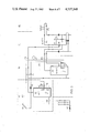
- FIG. 5 surveys one apparatus for performing the method according to the invention.
- the unheated water kW passes through a supply line 5 into a l.t. stage 10, where it is preheated by heat from l.t. heat sources, e.g., heat recovered from waste water, waste heat or remote heat, solar heat, heat pump heat, etc. It is also possible to use higher-grade, but inexpensive energy, such as, e.g., fermentation gas heat or low rate electric heat.
- the untreated water kW is heated from between 10° and 20° C. to approximately 40° C., in a low temperature heat tank or boiler 12.
- the highertemperature water is passed via a line 14, e.g., to a branch 16, from where it is either supplied by line 25 to the h.t. stage 20 or by line 15 to the mixing/distributor stage 30.
- the preheated water can also simultaneously flow to both stages.
- the preheated water flowing from the l.t. stage 10 via line 25 passes into the h.t. heat tank or boiler, where it is further heated.
- the requisite h.t. heat sources can be oil, electricity and coal, and inexpensive additional energy sources such as remote heat, fermentation gas, solar heat, etc., enabling such additional sources to be used as h.t. energy sources.
- the water is heated further to a temperature of, e.g., between 60° and 65° C.
- the water heated in the h.t. boiler passes via line 35 into mixer/distributor 32 of the mixing/distributor stage 30, which has a further l.t. water connection 38, apart from the h.t.
- any water temperature between 40° and 65° can be produced, i.e., according to FIG. 1, any temperature within the temperature program.
- the operation of the mixer/distributor 32 is described in detail in DOS No. 2,231,231, which in incorporated herein by reference.
- High temperature water is returned from the mixer/distributor stage 30 to the h.t. stage 20 via line 37.
- water can continue to flow via line 15 during deactivation of the h.t. stage, e.g., for showers or baths, for which h.t. water is not used.
- the use of h.t. water is controlled by the temperature program to a major extent and to a minor extent by the mixing of the h.t. water and l.t. water supply.
- the hot water flows via line 45 into the consumption stage 40 to consumption point 42 with the corresponding draw-off points, and from there by means of circulation line 47 back to the mixer/distributor 32.
- the water circulating in the two lines 45, 47 between the mixer/distributor stage 30 and the consumption stage 40 is either only h.t. water, or l.t. water, or mixed water.
- a circuit-controlled or program-controlled unit 100 receives from each stage, control, temperature and other state data and transfers corresponding program-based control and/or regulating data to the individual stages. Such a control unit 100 can also supply other means 10', 20', 30', 40' in accordance with the program. This is indicated by the downwardly extending double arrows to the stages 10', 20', 30', 40' belonging to another unit.
- the l.t. boiler is a thermally stratified boiler with a temperature gradient, but with no water return.
- the stratification corresponds to the density of the water in the gravitational field.
- the supply and removal of cold or hot water are accomplished such that there is no serious disturbance to the temperature gradient parallel to the gravitation.
- the convection flow-producing heat exchangers are similarly arranged for this purpose.
- the heat exchange capacity is substantially at a maximum level by this arrangement.
- FIG. 6 shows an hydraulic diagram of an apparatus for performing the method according to the invention. As it is a simplified representation, the conventional details have been omitted.
- This embodiment involves a solar additional energy supply, although the solar cells can be replaced with a low temperature-producing heat pump. Thus, the illustrated l.t. tank could be replaced by a heat pump tank.
- individual functional stages are shown, which correspond to the corresponding stages of FIG. 5 and are also given the same reference numerals.
- the l.t. stage 10 comprises a solar cell A4 with the associated lines F7, a cold water pretank A1 corresponding to the l.t. tank 12, a heat exchanger WT for transferring l.t.
- heat recovery means F6 a connection KW for the cold water from a cold water distribution battery or source A3, as well as the possibility of an additional electrical heating system.
- the corresponding low temperature line system is designated F3.
- the h.t. stage 20 comprises a hot water boiler A2 with a l.t. water supply from the line system F3, a heat exchanger WT for transferring low temperature heat from the solar cell system A4 via line system F7, as well as connections for lines F1 and F2, through which a h.t. water circulates in the direction of the arrows.
- the high temperature tank A2 can also be heated with additional energy, e.g., electrical power or from an oil firing system.
- a heat exchanger 7 is maintained at the operating temperature by the h.t. water circuit in lines F1 and F2 via h.t. tank A2.
- a further circuit leading to this heat exchanger is represented by line system F4, F5, F8.
- the final line system leads to the mixed water circuit maintained at the intended mixed water temperature in heat exchanger 7.
- This mixed water circuit leads via lines F4 and F5 to the consumption stage 40 with the corresponding draw-off points and is operated by a pump associated with the circuit.
- Various thermal sensors located in this distribution system control the corresponding motor-operated valves for the adequate mixing of the service water supplied or for switching from h.t. water or l.t. water at the draw-off points.
- This hydraulic diagram directly shows the interaction of the two h.t. and l.t. tanks.
- a significant drop in the energy content in the l.t. tank can be temporarily compensated for by the energy content of the h.t. tank by admixing.
- the temperature is raised again by heat pumps or solar energy in the l.t. tank.
- the temperature is raised by electric power or oil firing during the activation times corresponding to energy pulses P in FIG. 4.
- Additional programming in the electric circuit for the valve control regulates the switching on and off during the consumption peaks. Since inexpensive lower temperature water cannot satisfy the peak demands, including that of higher temperature water, oil or electric power is used to a limited extent and in an economical manner.
- FIGS. 7 and 8 show the hydraulic diagrams of two embodiments for apparatus according to the present invention.
- the l.t. stage 10 for preheating the service water employs alternative energy in the form of heat pump thermal energy.
- the h.t. stage 20 for heating the service water compensates for deficienceies.
- Distributor/mixer stage 30 mixes h.t. water with l.t. water at a service water temperature.
- Distributor stage 30 can comprise a single distribution battery as illustrated in FIG. 7 or a distribution battery with recirculation and heat exchanger 7 as illustrated in FIG. 8. The efficiency is further increased or the hot water heating costs further reduced by the recirculation via the heat exchanger of FIG. 8 as compared with the h.t. stage of FIG. 7.
- Consumer stage 40 in both embodiments completes the apparatus.
- a control unit 100 is provided for the monitoring, controlling and regulating of the apparatus.
- FIGS. 9 and 10 illustrate other embodiments in which l.t. stages 10 are operated by solar heat and by a further alternative heat source A4 supplied, e.g., by fermentation heat, remote heat, etc., providing higher temperature energy.
- Various heat exchangers WT are arranged along the temperature gradient in various heat zones or layers, as a function of the temperature of the heat supplied.
- the dense cold water is introduced at inlet KW into tank A1 at its bottom.
- a heat exchanger is located above inlet KW for supplying at F6, e.g., low temperature waste heat or return heat to be exchanged with maximum efficiency in the coldest layer of the tank. Further upwards, i.e., in the already preheated layer and consequently with a somewhat reduced efficiency, solar heat is supplied via its heat exchanger WT1. Still higher a heat exchanger WT2 with the highest energy concentration is located.
- the mixing/distributing stage 30 is shown in FIG. 9 as a single distributing battery with recirculation via lines F1, F2 in boiler A2, and in FIG. 10 as being separated hydraulically from boiler A2 by means of a heat exchanger 7.
- the waste heat, for transfer to the l.t. tank, can be provided by the thermal energy from ironing machines, tumble dryers, cooling systems, kitchen heating systems, etc. This more particularly applies in large units such as hospitals, hotels, barracks, etc. Return heat is mostly obtained from hot waste water. As a result of the thermal stratification, it is possible in very large l.t. tanks to adequately reuse any thermal energy from different sources.
- the following cost survey shows the effectiveness of the system of the present invention for an apartment and business building with eight units. Hot water costs are reduced almost 78% over a 12 month period. This means that expenditure for hot water, as a result of the reorganization according to the invention, now only amounts to one-sixth of the previous expenditure. As this building is heated with oil, the percentage saving for oil is naturally lower, because account must be taken of the overall heating. However, about a third can be saved on the total heating oil costs for hot water and heating.
Landscapes
- Engineering & Computer Science (AREA)
- Physics & Mathematics (AREA)
- Thermal Sciences (AREA)
- Chemical & Material Sciences (AREA)
- Combustion & Propulsion (AREA)
- Mechanical Engineering (AREA)
- General Engineering & Computer Science (AREA)
- Heat-Pump Type And Storage Water Heaters (AREA)
- Steam Or Hot-Water Central Heating Systems (AREA)
Applications Claiming Priority (2)
| Application Number | Priority Date | Filing Date | Title |
|---|---|---|---|
| CH10682 | 1982-01-08 | ||
| CH106/82 | 1982-01-08 |
Publications (1)
| Publication Number | Publication Date |
|---|---|
| US4537348A true US4537348A (en) | 1985-08-27 |
Family
ID=4179406
Family Applications (1)
| Application Number | Title | Priority Date | Filing Date |
|---|---|---|---|
| US06/453,931 Expired - Fee Related US4537348A (en) | 1982-01-08 | 1982-12-28 | System for efficient service water heating |
Country Status (4)
| Country | Link |
|---|---|
| US (1) | US4537348A (de) |
| EP (1) | EP0085774B1 (de) |
| AT (1) | ATE20772T1 (de) |
| DE (1) | DE3272047D1 (de) |
Cited By (23)
| Publication number | Priority date | Publication date | Assignee | Title |
|---|---|---|---|---|
| US4821955A (en) * | 1988-01-29 | 1989-04-18 | Acutherm, Ltd. | Thermally-powered active master and passive satellite air diffuser system |
| US4966127A (en) * | 1988-01-19 | 1990-10-30 | Martinez Jr George | Method and apparatus for saving energy in direct fired boilers |
| WO2006001780A1 (en) * | 2004-06-25 | 2006-01-05 | Ladislav Babej | Modular heat exchanger |
| US7690395B2 (en) | 2004-01-12 | 2010-04-06 | Masco Corporation Of Indiana | Multi-mode hands free automatic faucet |
| ITVA20100014A1 (it) * | 2010-02-10 | 2011-08-11 | Ca Ma Di S R L | Sistema di recupero di energia termica da reflui liquidi e gassosi di una cucina industriale o impianto similare |
| ES2365281A1 (es) * | 2008-10-01 | 2011-09-28 | Universidad Politécnica de Madrid | Sistema de agua caliente sanitaria por energía solar con recuperación de energía residual. |
| US8089473B2 (en) | 2006-04-20 | 2012-01-03 | Masco Corporation Of Indiana | Touch sensor |
| US8118240B2 (en) | 2006-04-20 | 2012-02-21 | Masco Corporation Of Indiana | Pull-out wand |
| US8162236B2 (en) | 2006-04-20 | 2012-04-24 | Masco Corporation Of Indiana | Electronic user interface for electronic mixing of water for residential faucets |
| US20120227953A1 (en) * | 2011-03-10 | 2012-09-13 | Gu-Sung Engineering & Construction Co., Ltd. | Energy-saving central heating and hot water supply system |
| US20120272948A1 (en) * | 2009-08-25 | 2012-11-01 | Danfoss A/S | Heat storage system |
| US8365767B2 (en) | 2006-04-20 | 2013-02-05 | Masco Corporation Of Indiana | User interface for a faucet |
| US8376313B2 (en) | 2007-03-28 | 2013-02-19 | Masco Corporation Of Indiana | Capacitive touch sensor |
| US8469056B2 (en) | 2007-01-31 | 2013-06-25 | Masco Corporation Of Indiana | Mixing valve including a molded waterway assembly |
| US8561626B2 (en) | 2010-04-20 | 2013-10-22 | Masco Corporation Of Indiana | Capacitive sensing system and method for operating a faucet |
| US8613419B2 (en) | 2007-12-11 | 2013-12-24 | Masco Corporation Of Indiana | Capacitive coupling arrangement for a faucet |
| US8776817B2 (en) | 2010-04-20 | 2014-07-15 | Masco Corporation Of Indiana | Electronic faucet with a capacitive sensing system and a method therefor |
| US20150013336A1 (en) * | 2012-03-09 | 2015-01-15 | Diamond Engineering Limited | Renewable energy storage system |
| US8944105B2 (en) | 2007-01-31 | 2015-02-03 | Masco Corporation Of Indiana | Capacitive sensing apparatus and method for faucets |
| US9175458B2 (en) | 2012-04-20 | 2015-11-03 | Delta Faucet Company | Faucet including a pullout wand with a capacitive sensing |
| US9243392B2 (en) | 2006-12-19 | 2016-01-26 | Delta Faucet Company | Resistive coupling for an automatic faucet |
| US9243756B2 (en) | 2006-04-20 | 2016-01-26 | Delta Faucet Company | Capacitive user interface for a faucet and method of forming |
| EP3502809A1 (de) * | 2017-12-22 | 2019-06-26 | Electricité de France | Verfahren zur steuerung von brauchwarmwasserboilern |
Families Citing this family (2)
| Publication number | Priority date | Publication date | Assignee | Title |
|---|---|---|---|---|
| DE102007004701B4 (de) * | 2007-01-31 | 2009-02-05 | Robert Bosch Gmbh | Verfahren zum Betreiben eines Mischers einer Heizungsanlage |
| CN114174725A (zh) * | 2019-08-08 | 2022-03-11 | 索维罗能源有限公司 | 建筑物的综合热管理 |
Citations (11)
| Publication number | Priority date | Publication date | Assignee | Title |
|---|---|---|---|---|
| US3946802A (en) * | 1973-10-09 | 1976-03-30 | Rune Christenson | Method and apparatus for heat recovery |
| US4034912A (en) * | 1976-06-07 | 1977-07-12 | Johnson Controls, Inc. | Method and control arrangement for a heating system including solar and fuel-fired heating apparatus |
| US4044949A (en) * | 1976-02-26 | 1977-08-30 | Ernst Morawetz | Heat storage system |
| US4143814A (en) * | 1976-09-08 | 1979-03-13 | Ultimate Engineering Corporation | Control and transfer of energy |
| US4165732A (en) * | 1975-11-18 | 1979-08-28 | Pechiney Ugine Kuhlmann | Process and apparatus for obtaining hot water by use of solar energy |
| US4189096A (en) * | 1976-12-06 | 1980-02-19 | Messier | Central heating plant |
| US4213563A (en) * | 1977-07-15 | 1980-07-22 | Patlico Rights N.V. | Heat storage and transmission apparatus for heat from a fluid heated by the sun |
| US4323192A (en) * | 1979-01-23 | 1982-04-06 | Plympton Patents Limited | Control arrangements for heating circuits |
| US4345583A (en) * | 1978-08-21 | 1982-08-24 | Pechiney Ugine Kuhlmann | Water heater using solar and non-solar energy |
| US4350144A (en) * | 1980-08-18 | 1982-09-21 | Stanford Associates, Inc. | Hot water heating system |
| US4406136A (en) * | 1980-06-04 | 1983-09-27 | Picchiottino Andre A | Heating installation notably for space heating and for sanitary hot water production |
Family Cites Families (2)
| Publication number | Priority date | Publication date | Assignee | Title |
|---|---|---|---|---|
| DE2930187B1 (de) * | 1979-07-25 | 1981-01-22 | Bosch Siemens Hausgeraete | Warmwasserversorgungsanlage |
| FR2468074A1 (fr) * | 1979-10-23 | 1981-04-30 | Omnium Tech Etu Const Equip | Installation perfectionnee a pompe a chaleur pour la production d'eau chaude |
-
1982
- 1982-12-11 AT AT82111509T patent/ATE20772T1/de not_active IP Right Cessation
- 1982-12-11 DE DE8282111509T patent/DE3272047D1/de not_active Expired
- 1982-12-11 EP EP82111509A patent/EP0085774B1/de not_active Expired
- 1982-12-28 US US06/453,931 patent/US4537348A/en not_active Expired - Fee Related
Patent Citations (11)
| Publication number | Priority date | Publication date | Assignee | Title |
|---|---|---|---|---|
| US3946802A (en) * | 1973-10-09 | 1976-03-30 | Rune Christenson | Method and apparatus for heat recovery |
| US4165732A (en) * | 1975-11-18 | 1979-08-28 | Pechiney Ugine Kuhlmann | Process and apparatus for obtaining hot water by use of solar energy |
| US4044949A (en) * | 1976-02-26 | 1977-08-30 | Ernst Morawetz | Heat storage system |
| US4034912A (en) * | 1976-06-07 | 1977-07-12 | Johnson Controls, Inc. | Method and control arrangement for a heating system including solar and fuel-fired heating apparatus |
| US4143814A (en) * | 1976-09-08 | 1979-03-13 | Ultimate Engineering Corporation | Control and transfer of energy |
| US4189096A (en) * | 1976-12-06 | 1980-02-19 | Messier | Central heating plant |
| US4213563A (en) * | 1977-07-15 | 1980-07-22 | Patlico Rights N.V. | Heat storage and transmission apparatus for heat from a fluid heated by the sun |
| US4345583A (en) * | 1978-08-21 | 1982-08-24 | Pechiney Ugine Kuhlmann | Water heater using solar and non-solar energy |
| US4323192A (en) * | 1979-01-23 | 1982-04-06 | Plympton Patents Limited | Control arrangements for heating circuits |
| US4406136A (en) * | 1980-06-04 | 1983-09-27 | Picchiottino Andre A | Heating installation notably for space heating and for sanitary hot water production |
| US4350144A (en) * | 1980-08-18 | 1982-09-21 | Stanford Associates, Inc. | Hot water heating system |
Non-Patent Citations (1)
| Title |
|---|
| European Search Report, EP 82 11 1509. * |
Cited By (39)
| Publication number | Priority date | Publication date | Assignee | Title |
|---|---|---|---|---|
| US4966127A (en) * | 1988-01-19 | 1990-10-30 | Martinez Jr George | Method and apparatus for saving energy in direct fired boilers |
| US4821955A (en) * | 1988-01-29 | 1989-04-18 | Acutherm, Ltd. | Thermally-powered active master and passive satellite air diffuser system |
| US7690395B2 (en) | 2004-01-12 | 2010-04-06 | Masco Corporation Of Indiana | Multi-mode hands free automatic faucet |
| US9243391B2 (en) | 2004-01-12 | 2016-01-26 | Delta Faucet Company | Multi-mode hands free automatic faucet |
| US8528579B2 (en) | 2004-01-12 | 2013-09-10 | Masco Corporation Of Indiana | Multi-mode hands free automatic faucet |
| WO2006001780A1 (en) * | 2004-06-25 | 2006-01-05 | Ladislav Babej | Modular heat exchanger |
| US8162236B2 (en) | 2006-04-20 | 2012-04-24 | Masco Corporation Of Indiana | Electronic user interface for electronic mixing of water for residential faucets |
| US9285807B2 (en) | 2006-04-20 | 2016-03-15 | Delta Faucet Company | Electronic user interface for electronic mixing of water for residential faucets |
| US9243756B2 (en) | 2006-04-20 | 2016-01-26 | Delta Faucet Company | Capacitive user interface for a faucet and method of forming |
| US8089473B2 (en) | 2006-04-20 | 2012-01-03 | Masco Corporation Of Indiana | Touch sensor |
| US8243040B2 (en) | 2006-04-20 | 2012-08-14 | Masco Corporation Of Indiana | Touch sensor |
| US11886208B2 (en) | 2006-04-20 | 2024-01-30 | Delta Faucet Company | Electronic user interface for electronic mixing of water for residential faucets |
| US10698429B2 (en) | 2006-04-20 | 2020-06-30 | Delta Faucet Company | Electronic user interface for electronic mixing of water for residential faucets |
| US8365767B2 (en) | 2006-04-20 | 2013-02-05 | Masco Corporation Of Indiana | User interface for a faucet |
| US9228329B2 (en) | 2006-04-20 | 2016-01-05 | Delta Faucet Company | Pull-out wand |
| US8118240B2 (en) | 2006-04-20 | 2012-02-21 | Masco Corporation Of Indiana | Pull-out wand |
| US9856634B2 (en) | 2006-04-20 | 2018-01-02 | Delta Faucet Company | Fluid delivery device with an in-water capacitive sensor |
| US9715238B2 (en) | 2006-04-20 | 2017-07-25 | Delta Faucet Company | Electronic user interface for electronic mixing of water for residential faucets |
| US8844564B2 (en) | 2006-12-19 | 2014-09-30 | Masco Corporation Of Indiana | Multi-mode hands free automatic faucet |
| US8127782B2 (en) | 2006-12-19 | 2012-03-06 | Jonte Patrick B | Multi-mode hands free automatic faucet |
| US9243392B2 (en) | 2006-12-19 | 2016-01-26 | Delta Faucet Company | Resistive coupling for an automatic faucet |
| US8469056B2 (en) | 2007-01-31 | 2013-06-25 | Masco Corporation Of Indiana | Mixing valve including a molded waterway assembly |
| US8944105B2 (en) | 2007-01-31 | 2015-02-03 | Masco Corporation Of Indiana | Capacitive sensing apparatus and method for faucets |
| US8376313B2 (en) | 2007-03-28 | 2013-02-19 | Masco Corporation Of Indiana | Capacitive touch sensor |
| US9315976B2 (en) | 2007-12-11 | 2016-04-19 | Delta Faucet Company | Capacitive coupling arrangement for a faucet |
| US8613419B2 (en) | 2007-12-11 | 2013-12-24 | Masco Corporation Of Indiana | Capacitive coupling arrangement for a faucet |
| ES2365281A1 (es) * | 2008-10-01 | 2011-09-28 | Universidad Politécnica de Madrid | Sistema de agua caliente sanitaria por energía solar con recuperación de energía residual. |
| US9175865B2 (en) * | 2009-08-25 | 2015-11-03 | Danfoss A/S | Heat storage system |
| US20120272948A1 (en) * | 2009-08-25 | 2012-11-01 | Danfoss A/S | Heat storage system |
| ITVA20100014A1 (it) * | 2010-02-10 | 2011-08-11 | Ca Ma Di S R L | Sistema di recupero di energia termica da reflui liquidi e gassosi di una cucina industriale o impianto similare |
| US8776817B2 (en) | 2010-04-20 | 2014-07-15 | Masco Corporation Of Indiana | Electronic faucet with a capacitive sensing system and a method therefor |
| US9394675B2 (en) | 2010-04-20 | 2016-07-19 | Delta Faucet Company | Capacitive sensing system and method for operating a faucet |
| US8561626B2 (en) | 2010-04-20 | 2013-10-22 | Masco Corporation Of Indiana | Capacitive sensing system and method for operating a faucet |
| US9175864B2 (en) * | 2011-03-10 | 2015-11-03 | Gu-Sung Engineering & Construction Co., Ltd. | Energy-saving central heating and hot water supply system |
| US20120227953A1 (en) * | 2011-03-10 | 2012-09-13 | Gu-Sung Engineering & Construction Co., Ltd. | Energy-saving central heating and hot water supply system |
| US20150013336A1 (en) * | 2012-03-09 | 2015-01-15 | Diamond Engineering Limited | Renewable energy storage system |
| US9175458B2 (en) | 2012-04-20 | 2015-11-03 | Delta Faucet Company | Faucet including a pullout wand with a capacitive sensing |
| EP3502809A1 (de) * | 2017-12-22 | 2019-06-26 | Electricité de France | Verfahren zur steuerung von brauchwarmwasserboilern |
| FR3075933A1 (fr) * | 2017-12-22 | 2019-06-28 | Electricite De France | Procede de pilotage de ballons d'eau chaude sanitaire |
Also Published As
| Publication number | Publication date |
|---|---|
| ATE20772T1 (de) | 1986-08-15 |
| EP0085774A1 (de) | 1983-08-17 |
| EP0085774B1 (de) | 1986-07-16 |
| DE3272047D1 (en) | 1986-08-21 |
Similar Documents
| Publication | Publication Date | Title |
|---|---|---|
| EP0085774B1 (de) | Verfahren zur energiesparenden Warmwasserbereitung in Wohnbauten, insbesondere in Gross- und Mittelgrossbauten, und Einrichtung zur Durchführung des Verfahrens | |
| CN109827221A (zh) | 一种基于多种清洁能源的模块化组合式智能供热系统 | |
| CN105698318A (zh) | 一种供冷供热能源站及方法 | |
| CN111520801B (zh) | 一种地暖模块化电加热系统 | |
| EP1277016B1 (de) | Zentralheizungsanlage für wärmebenutzer mit wärmespeicher | |
| CN200996728Y (zh) | 一种太阳能配空气能节能热水系统 | |
| WO2013040731A1 (zh) | 一种适宜热带地区使用的太阳能热水系统 | |
| CN201032223Y (zh) | 一种太阳能-热泵分级加热式储能的热水装置 | |
| CN219454050U (zh) | 一种燃气锅炉和空气源热泵的耦合供热系统 | |
| CN1892142B (zh) | 太阳能-热泵复合、分级加热式储能热水制作方法及其专用装置 | |
| CN201368525Y (zh) | 生活热水及采暖用水共用热源的蓄热装置 | |
| WO2024061391A1 (en) | A method of regulating the temperature of domestic hot water and circulating heating system for its implementation | |
| CN213040627U (zh) | 一种地暖模块化电加热器 | |
| CN209857180U (zh) | 一种分时分区控制系统 | |
| CN108758775B (zh) | 一种利用太阳能的智能供热系统 | |
| CN219510886U (zh) | 一种北方农村供暖智能控制系统 | |
| US4852547A (en) | Heat storage | |
| EP1159567B1 (de) | Heizanlage | |
| CN1364991A (zh) | 分户分室与单户分室供暖系统 | |
| CN2192019Y (zh) | 一种汽水两用蓄热器 | |
| KR200370859Y1 (ko) | 난방 및 급탕 온수 공급 시스템 | |
| CN102927614A (zh) | 一种全自动储热式太阳能中央智能集中供暖热水系统 | |
| CN220624432U (zh) | 一种壁挂式光伏电热水系统 | |
| SU1260642A1 (ru) | Способ получени воды дл гор чего водоснабжени | |
| JPH081344B2 (ja) | マルチ給湯システム |
Legal Events
| Date | Code | Title | Description |
|---|---|---|---|
| FEPP | Fee payment procedure |
Free format text: PAYER NUMBER DE-ASSIGNED (ORIGINAL EVENT CODE: RMPN); ENTITY STATUS OF PATENT OWNER: SMALL ENTITY Free format text: PAYOR NUMBER ASSIGNED (ORIGINAL EVENT CODE: ASPN); ENTITY STATUS OF PATENT OWNER: SMALL ENTITY |
|
| FEPP | Fee payment procedure |
Free format text: PAYOR NUMBER ASSIGNED (ORIGINAL EVENT CODE: ASPN); ENTITY STATUS OF PATENT OWNER: SMALL ENTITY |
|
| FPAY | Fee payment |
Year of fee payment: 4 |
|
| FPAY | Fee payment |
Year of fee payment: 8 |
|
| REMI | Maintenance fee reminder mailed | ||
| LAPS | Lapse for failure to pay maintenance fees | ||
| FP | Lapsed due to failure to pay maintenance fee |
Effective date: 19970827 |
|
| STCH | Information on status: patent discontinuation |
Free format text: PATENT EXPIRED DUE TO NONPAYMENT OF MAINTENANCE FEES UNDER 37 CFR 1.362 |