US4544947A - Adjustment-free drive circuit for color television picture tubes - Google Patents
Adjustment-free drive circuit for color television picture tubes Download PDFInfo
- Publication number
- US4544947A US4544947A US06/465,497 US46549783A US4544947A US 4544947 A US4544947 A US 4544947A US 46549783 A US46549783 A US 46549783A US 4544947 A US4544947 A US 4544947A
- Authority
- US
- United States
- Prior art keywords
- inverting input
- amplifier
- output
- drive circuit
- signal
- Prior art date
- Legal status (The legal status is an assumption and is not a legal conclusion. Google has not performed a legal analysis and makes no representation as to the accuracy of the status listed.)
- Expired - Fee Related
Links
- 230000006870 function Effects 0.000 claims description 4
- 230000005540 biological transmission Effects 0.000 description 3
- 230000000694 effects Effects 0.000 description 3
- 238000000034 method Methods 0.000 description 3
- 230000032683 aging Effects 0.000 description 2
- 238000006243 chemical reaction Methods 0.000 description 2
- 238000004519 manufacturing process Methods 0.000 description 2
- 230000007935 neutral effect Effects 0.000 description 2
- TZCXTZWJZNENPQ-UHFFFAOYSA-L barium sulfate Chemical compound [Ba+2].[O-]S([O-])(=O)=O TZCXTZWJZNENPQ-UHFFFAOYSA-L 0.000 description 1
- 230000006399 behavior Effects 0.000 description 1
- 239000003086 colorant Substances 0.000 description 1
- 239000002131 composite material Substances 0.000 description 1
- 238000010276 construction Methods 0.000 description 1
- 238000010586 diagram Methods 0.000 description 1
- 230000008030 elimination Effects 0.000 description 1
- 238000003379 elimination reaction Methods 0.000 description 1
- 230000006872 improvement Effects 0.000 description 1
- 238000012986 modification Methods 0.000 description 1
- 230000004048 modification Effects 0.000 description 1
- 230000003287 optical effect Effects 0.000 description 1
- 230000008569 process Effects 0.000 description 1
Images
Classifications
-
- H—ELECTRICITY
- H04—ELECTRIC COMMUNICATION TECHNIQUE
- H04N—PICTORIAL COMMUNICATION, e.g. TELEVISION
- H04N9/00—Details of colour television systems
- H04N9/64—Circuits for processing colour signals
- H04N9/648—Video amplifiers
Definitions
- the invention relates to an adjustment-free drive circuit for color television picture tubes.
- the picture tube In a color television transmission system, the picture tube is the last link in the transmission chain.
- the picture tube performs the conversion of electrical signals into optical signals. This conversion process was heretofore accomplished in a technically unsatisfactory manner, since the transfer characteristic of the picture tube which is in effect in the presently used circuits, has major tolerances.
- tolerances are not only manufacturing tolerances but also additional changes which occur during operation, due to temperature rise and aging.
- the possibility is provided in at least two of the three color channels, for adjusting the so-called black level or picture black and white level.
- the adjustment was mainly made manually, for instance, by selecting a point on the picture tube characteristic in the vicinity of the beam current for the black level cutoff. With the vertical deflection disconnected, a horizontal line is obtained on the picture screen, the color of which is adjusted so that a gray that is as neutral as possible is obtained. For adjusting the white level, a point in the range of the maximum beam current is selected. For this purpose, for instance, the color bar test picture can be used, in which the reproduced white area is to be adjusted to a white that is as neutral as possible.
- an adjustment-free drive circuit for color television picture tubes comprising an amplifier having a non-inverting input receiving an equalized signal of an individual color component red, green or blue as a reference value, an inverting input receiving a voltage proportional to the actual value of the cathode current, and an output, the reference value at the non-inverting input being compared in the amplifier with the actual value at the inverting input for issuing a signal at the output of the amplifier having the smallest possible difference between the desired and actual values, the output of the amplifier being connected to the control grid of a picture tube for applying the signal issued at the output thereto.
- a linear network connected to the non-inverting input for equalizing the individual color component signals with an artificial picture tube characteristic.
- a read-only memory storing an inverse function of a predistortion characteristic on the transmitter side, the read-only memory receiving digitalized signals of the individual color component, and a digital-to-analog converter connected between the read-only memory and the non-inverting input of the amplifier for applying the equalized signal.
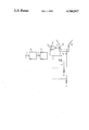
- FIGURE of the drawing is a schematic and diagrammatic circuit diagram of an embodiment of the invention.
- the drive circuit according to the invention operates with a current control, contrary to the commonly used voltage controls. This achieves the result that none of the picture tube tolerances have an effect, since the cathode current is determined and impressed by the drive circuit alone. The curvature of the picture tube characteristic is likewise compensated in this case.
- the video signal is predistorted on the transmitter side by a characteristic which corresponds mathematically exactly to the inverse function of the picture tube characteristic. Since the overall transmission system should again have linear transfer behavior, an artificial picture tube characteristic must be inserted in the current-control mode of operation of the picture tube. This can be accomplished, for instance, through a suitably constructed linear network or by a read-only memory as is shown in the FIGURE, which is advantageous in the case of a digital system. It is shown in the FIGURE that the digital signal R of the color red controls address inputs of a read-only memory 6 through an input 1. In the read-only memory (ROM) 6, the inverse function of the predistortion characteristic on the transmitter side is contained in a mathematically exact form.
- the equalized signal of the color red is therefore present at the output 2 of the read-only memory 6.
- the output signal of the memory 6 is converted into an analog signal which represents the desired value for an apmlifier 8 and is fed to a non-inverting input 3 of the amplifier 8.
- a voltage proportional to the actual value of the cathode current is taken off at a resistor 10.
- the voltage addresses an inverting input 4 of the amplifier 8.
- the desired value at the point 3 is compared with the actual value at the point 4 and a signal appears at an output 5 in which the difference between the desired and the actual value is minimized.
- the output 5 of the amplifier directly controls the control grid 11 of the color television picture tube 9.
- the advantages of the drive circuit according to the invention are that neither a black value nor a white value adjustment is required. Changes of the picture tube characteristic due to temperature and aging have no effect. Furthermore, a very accurate compensation of the predistortion on the transmitter side can be accomplished by the equalizing network in the ROM 6.
Landscapes
- Engineering & Computer Science (AREA)
- Multimedia (AREA)
- Signal Processing (AREA)
- Processing Of Color Television Signals (AREA)
- Testing, Inspecting, Measuring Of Stereoscopic Televisions And Televisions (AREA)
- Color Television Image Signal Generators (AREA)
Applications Claiming Priority (2)
| Application Number | Priority Date | Filing Date | Title |
|---|---|---|---|
| DE19823204744 DE3204744A1 (de) | 1982-02-11 | 1982-02-11 | Abgleichfreie ansteuerschaltung fuer farbfernseh-bildroehren |
| DE3204744 | 1982-02-11 |
Publications (1)
| Publication Number | Publication Date |
|---|---|
| US4544947A true US4544947A (en) | 1985-10-01 |
Family
ID=6155374
Family Applications (1)
| Application Number | Title | Priority Date | Filing Date |
|---|---|---|---|
| US06/465,497 Expired - Fee Related US4544947A (en) | 1982-02-11 | 1983-02-10 | Adjustment-free drive circuit for color television picture tubes |
Country Status (5)
| Country | Link |
|---|---|
| US (1) | US4544947A (de) |
| EP (1) | EP0086464B1 (de) |
| JP (1) | JPS58147292A (de) |
| AT (1) | ATE10995T1 (de) |
| DE (2) | DE3204744A1 (de) |
Citations (1)
| Publication number | Priority date | Publication date | Assignee | Title |
|---|---|---|---|---|
| US4053927A (en) * | 1975-03-18 | 1977-10-11 | Licentia Patent-Verwaltungs-G.M.B.H. | Chrominance amplifier control circuit providing simultaneous adjustment of gain and DC level |
Family Cites Families (1)
| Publication number | Priority date | Publication date | Assignee | Title |
|---|---|---|---|---|
| GB1432254A (en) * | 1972-06-15 | 1976-04-14 | Bang & Olufsen As | Television receivers |
-
1982
- 1982-02-11 DE DE19823204744 patent/DE3204744A1/de not_active Withdrawn
-
1983
- 1983-02-07 JP JP58018737A patent/JPS58147292A/ja active Pending
- 1983-02-10 AT AT83101290T patent/ATE10995T1/de active
- 1983-02-10 EP EP83101290A patent/EP0086464B1/de not_active Expired
- 1983-02-10 DE DE8383101290T patent/DE3360036D1/de not_active Expired
- 1983-02-10 US US06/465,497 patent/US4544947A/en not_active Expired - Fee Related
Patent Citations (1)
| Publication number | Priority date | Publication date | Assignee | Title |
|---|---|---|---|---|
| US4053927A (en) * | 1975-03-18 | 1977-10-11 | Licentia Patent-Verwaltungs-G.M.B.H. | Chrominance amplifier control circuit providing simultaneous adjustment of gain and DC level |
Also Published As
| Publication number | Publication date |
|---|---|
| EP0086464B1 (de) | 1984-12-27 |
| JPS58147292A (ja) | 1983-09-02 |
| DE3204744A1 (de) | 1983-08-18 |
| EP0086464A1 (de) | 1983-08-24 |
| DE3360036D1 (en) | 1985-02-07 |
| ATE10995T1 (de) | 1985-01-15 |
Similar Documents
| Publication | Publication Date | Title |
|---|---|---|
| GB2042308A (en) | Automatic crt biasing system | |
| CA1142641A (en) | Automatic kinescope biasing system with increased interference immunity | |
| EP0392833A1 (de) | Einrichtung zur digitalen Regelung des Gleichstromwertes eines Signals | |
| US4544947A (en) | Adjustment-free drive circuit for color television picture tubes | |
| US4499494A (en) | Television gamma corrector with symmetrical response about black-level | |
| US2773116A (en) | Luminance correction apparatus for color television systems | |
| US4523222A (en) | Set of three integrated circuits for digital video signal processing in color-television receivers | |
| EP0331506B1 (de) | System zur automatischen Verstärkungsregelung | |
| EP0074081B1 (de) | Signalverarbeitungseinheit | |
| US3701843A (en) | Matrix amplifier network with novel d-c set-up arrangement | |
| US4521811A (en) | Beam current limiting arrangement for a digital television system | |
| WO1991011076A2 (en) | Video display system | |
| US4506287A (en) | Color television camera apparatus | |
| EP0932309A2 (de) | Verfahren und Vorrichtung zur Konvergenzkorrektur in einem Fernsehempfänger | |
| US5182497A (en) | Cathode clamping circuit apparatus with digital control | |
| US2845573A (en) | Color kinescope biasing system | |
| US2823254A (en) | Color television receiver | |
| US3967312A (en) | Color television chroma demodulator circuit | |
| US3737563A (en) | Color television receiver | |
| KR930010002B1 (ko) | 영상표시용 비디오 장치 | |
| US4688083A (en) | Circuit arrangement for matrixing three chroma signals to obtain color difference and a luminance signal | |
| EP0111521B2 (de) | Videosteuerschaltung und verfahren zur automatischen grauwertregelung und beseitigung von kontrastgleichlauffehlern | |
| KR0149873B1 (ko) | 고품위tv신호/표준tv신호 컨버터 | |
| US3303277A (en) | Colour television receiver including clipper correction means | |
| KR100225578B1 (ko) | 감마 보정 회로 |
Legal Events
| Date | Code | Title | Description |
|---|---|---|---|
| AS | Assignment |
Owner name: SIEMENS AKTIENGESELLSCHAFT, BERLIN AND MUNCHEN, GE Free format text: ASSIGNMENT OF ASSIGNORS INTEREST.;ASSIGNOR:HAUSSMANN, WOLFGANG;REEL/FRAME:004426/0965 Effective date: 19830119 |
|
| FEPP | Fee payment procedure |
Free format text: PAYOR NUMBER ASSIGNED (ORIGINAL EVENT CODE: ASPN); ENTITY STATUS OF PATENT OWNER: LARGE ENTITY |
|
| REMI | Maintenance fee reminder mailed | ||
| LAPS | Lapse for failure to pay maintenance fees | ||
| STCH | Information on status: patent discontinuation |
Free format text: PATENT EXPIRED DUE TO NONPAYMENT OF MAINTENANCE FEES UNDER 37 CFR 1.362 |
|
| FP | Lapsed due to failure to pay maintenance fee |
Effective date: 19891001 |