US4552660A - Plate filter having a movable filter cloth - Google Patents
Plate filter having a movable filter cloth Download PDFInfo
- Publication number
- US4552660A US4552660A US06/562,286 US56228683A US4552660A US 4552660 A US4552660 A US 4552660A US 56228683 A US56228683 A US 56228683A US 4552660 A US4552660 A US 4552660A
- Authority
- US
- United States
- Prior art keywords
- filter
- deflecting
- sprockets
- drive means
- roll
- Prior art date
- Legal status (The legal status is an assumption and is not a legal conclusion. Google has not performed a legal analysis and makes no representation as to the accuracy of the status listed.)
- Expired - Fee Related
Links
- 239000004744 fabric Substances 0.000 title claims abstract description 32
- 230000033001 locomotion Effects 0.000 claims abstract description 5
- 238000000034 method Methods 0.000 description 5
- 230000010006 flight Effects 0.000 description 3
- 238000010276 construction Methods 0.000 description 2
- 230000007246 mechanism Effects 0.000 description 2
- 125000006850 spacer group Chemical group 0.000 description 2
- 230000006978 adaptation Effects 0.000 description 1
- 239000000969 carrier Substances 0.000 description 1
- 238000006073 displacement reaction Methods 0.000 description 1
- 239000012065 filter cake Substances 0.000 description 1
- 238000012986 modification Methods 0.000 description 1
- 230000004048 modification Effects 0.000 description 1
- 230000001105 regulatory effect Effects 0.000 description 1
- 239000000725 suspension Substances 0.000 description 1
- 230000007723 transport mechanism Effects 0.000 description 1
- 238000004804 winding Methods 0.000 description 1
Images


Classifications
-
- B—PERFORMING OPERATIONS; TRANSPORTING
- B01—PHYSICAL OR CHEMICAL PROCESSES OR APPARATUS IN GENERAL
- B01D—SEPARATION
- B01D25/00—Filters formed by clamping together several filtering elements or parts of such elements
- B01D25/32—Removal of the filter cakes
- B01D25/322—Removal of the filter cakes specially for chamber filter presses
-
- B—PERFORMING OPERATIONS; TRANSPORTING
- B01—PHYSICAL OR CHEMICAL PROCESSES OR APPARATUS IN GENERAL
- B01D—SEPARATION
- B01D25/00—Filters formed by clamping together several filtering elements or parts of such elements
- B01D25/12—Filter presses, i.e. of the plate or plate and frame type
- B01D25/127—Filter presses, i.e. of the plate or plate and frame type with one or more movable filter bands arranged to be clamped between the press plates or between a plate and a frame during filtration, e.g. zigzag endless filter bands
- B01D25/1275—Filter presses, i.e. of the plate or plate and frame type with one or more movable filter bands arranged to be clamped between the press plates or between a plate and a frame during filtration, e.g. zigzag endless filter bands the plates or the frames being placed in a non-vertical position
-
- B—PERFORMING OPERATIONS; TRANSPORTING
- B01—PHYSICAL OR CHEMICAL PROCESSES OR APPARATUS IN GENERAL
- B01D—SEPARATION
- B01D29/00—Filters with filtering elements stationary during filtration, e.g. pressure or suction filters, not covered by groups B01D24/00 - B01D27/00; Filtering elements therefor
- B01D29/39—Filters with filtering elements stationary during filtration, e.g. pressure or suction filters, not covered by groups B01D24/00 - B01D27/00; Filtering elements therefor with hollow discs side by side on, or around, one or more tubes, e.g. of the leaf type
- B01D29/41—Filters with filtering elements stationary during filtration, e.g. pressure or suction filters, not covered by groups B01D24/00 - B01D27/00; Filtering elements therefor with hollow discs side by side on, or around, one or more tubes, e.g. of the leaf type mounted transversely on the tube
Definitions
- This invention relates to a plate filter having a plurality of shiftable filter elements comprising filter plates and frames arranged in an alternating sequence on a filter stand.
- the plate filter includes a filter element closing device which presses the filter elements together to form a compressed filter plate stack. At two opposite edges of some of the filter elements deflecting rolls are provided which support an endless filter cloth passing in a zigzag fashion between subsequent filter elements. At least some of the deflecting rolls are driven rolls.
- the plate filter further has a filter cloth driving mechanism which moves the filter cloth through the filter plate stack in the open (separated) state of the latter.
- At least some of the deflecting rolls are, at one side of the filter plate stack, at least at one roll end, provided with a sprocket affixed thereto which meshes with a flexible, form-locking and endless driving means interconnecting several sprockets and being driven by a drive motor.
- a plate filter of the above-outlined type including vertically oriented filter plates is disclosed in German Auslegeschrift (application published after examination) No. 2,012,400. It is a disadvantage of the known structure that upon closing the filter plate stack, the driving chain or driving belt length which is normally meshing with the sprockets from below, drops loose therefrom and hangs in a slack manner.
- two intersecting chains have to be positioned side-by-side so that in the closed state of the plate filter, side-by-side arranged, offset, slack chain lengths are present.
- the respective underlying return flight of the two chains is supported on end rollers on the stationary end plate as well as on the displaceable head plate of the plate filter so that upon closing of the plate filter the two return flights also hang loosely along their entire length.
- U.S. Pat. No. 4,289,622 discloses a filter cloth transporting mechanism in which the roller chain serving as the drive means is guided in such a manner by means of a combination of a sprocket and a deflecting roller in each filter element that the roller chain remains connected--independently from the open or closed state of the filter plate stack--the sprockets and the deflecting rolls even during the opening and closing motion of the filter elements. It is, however, a disadvantage of this structure that the entire driving output for the filter cloth transport has to be channelled through one roller chain, or more often, through two roller chains so that the roller chains have to be of sturdy construction. Further, this arrangement cannot be used in multiple drives for large filter units.
- the plate filter comprises a plurality of shiftable filter plates and first and second deflecting rolls carried on opposite sides of each filter plate.
- the axes of consecutive first deflecting rolls lie alternatingly in a first plane and in a second plane spaced from one another.
- a filter cloth is guided in a zigzag course between consecutive filter plates by the first and second deflecting rolls.
- a first sprocket is affixed to each first deflecting roll and a second sprocket is mounted on each first deflecting roll for free idling rotation.
- First and second spaced, elongated, oppositely driven chains are respectively trained in a zigzag course in an alternating sequence about first and second sprockets of first deflecting rolls belonging to consecutive filter plates.
- the first and second chains are in meshing relationship with the first and second sprockets about which the chains are consecutively trained.
- the diameter of the first and second sprockets and the distance between the first and second planes are dimensioned for varying the magnitude of a loop angle represented by an arc along which the first and second chains are in engagement with respective first and second sprockets to compensate for length variations of the first and second chains upon shifting motion of the filter plates relative to one another.
- each of the two parallel-running drive means preferably roller chains, are driven by their own drive motor to thus achieve a better distribution of tension for the filter cloth. It is of particular advantage to provide that the drive motor for one drive means is situated at one end of the filter plate stack whereas the drive motor for the other, parallel drive means is arranged at the other end of the filter plate stack.
- FIG. 1 is a schematic, partially sectional side elevational view of a preferred embodiment of the invention.
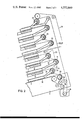
- FIG. 2 is an enlarged detail of FIG. 1.
- FIG. 3 is a top plan view of one part of FIG. 2.
- FIG. 4 is a sectional top plan view of the detail encircled at IV in FIG. 3.
- a filter stand beam 3 To the two opposite sloping sides of the base plate 1 there are fixedly secured guide carrier beams 2 and to the elevated side of the base plate 1 there is fixedly secured a filter stand beam 3.
- the three beams 2 and 3 are, at the upper end of the press stand, combined into a common transverse yoke 4 on which there is mounted a hydraulic closing cylinder 5.
- the piston rod (not visible in FIG. 1) of the closing cylinder 5 is coupled in a conventional manner with a head plate 6 displaceable parallel to the length of the plate filter.
- FIG. 1 shows the filter plate stack in an open state in which the filter elements 7, 8 are separated (spaced) from one another. For the sake of clarity each frame 8 is shown in section.
- each filter plate 7 On opposite two sides of each filter plate 7 there are mounted filter cloth deflecting rolls 11 and 12, respectively.
- the rolls 11 which are, because of the 15° inclination of the filter press, in the "high” position, have a larger diameter than the rolls 12 which are in the "low” position.
- a filter cloth 13 is guided by the rolls 11 and 12 in a zigzag fashion through the plate filter such that the filter cloth 13 in each instance moves past immediately at the upper side and the lower side of each filter plate 7 and passes between a filter plate 7 and a frame 8.
- the filter cloth 13 is, on the upper side of the filter plate stack (as determined by the inclined position of the plate filter) guided through a driving station 14, guide rolls 15 and a regulating device 16 as well as a tensioning device 17. From the tensioning device 17 the filter cloth 13 is passed through a driving station 18 mounted in the base plate 1. Thereafter, the filter cloth runs through the filter plate stack in a zigzag manner as described above.
- the filter plates 7 and the frames 8 are connected with one another in a known manner by means of a suspension device comprising, for example, a side bar chain which is so designed that in the open state of the plate filter, the space between a filter plate 7 and an underlying frame 8 is just large enough for allowing the filter cloth 13 to be pulled through, whereas the distance between a frame 8 and an underlying subsequent filter plate 7 is greater than the frame thickness so that the filter cake 19 whose height is determined by the thickness of the frame, may, as the filter cloth 13 is moved in the direction of the arrow 20 between the frame 8 and the underlying filter plate 7, move freely outwardly in the downward direction (as determined by the inclination of the filter press) and may be ejected onto a conveyor (not shown).
- a suspension device comprising, for example, a side bar chain which is so designed that in the open state of the plate filter, the space between a filter plate 7 and an underlying frame 8 is just large enough for allowing the filter cloth 13 to be pulled through, whereas the distance between
- the filter cloth 13 is driven as shown in FIGS. 2 and 3.
- the deflecting rolls 11 are each supported on a filter plate 7 by means of respective support arms 21.
- This arrangement is so designed that the axes of the consecutive deflecting rolls 11 are lying alternatingly in two parallel-oriented planes 22 and 23.
- To each deflecting roll 11 there is fixedly attached a sprocket 24 and, coaxially therewith, there is mounted for free, idling rotation a further sprocket 25.
- the distance between the two planes 22 and 23 is greater than the diameter of the sprocket 24 or 25, so that when the filter elements are pushed together to assume the closed position, the sprockets whose axis lies in the plane 22 may move past the sprockets whose axis lies in the plane 23.
- each fixed sprocket 24 is followed by an idling sprocket 25.
- roller chains 26 and 27 are, in the end zone of the filter plate stack, in a meshing relationship with a driving cylinder 28 and 29 rotated in the same sense by a drive motor.
- the filter cloth 13 is also trained about the cylinders 28 and 29.
- the idling (return) flights of the two side-by-side arranged roller chains 26 and 27 are guided over a deflecting pinion 30 and a weight-biased or spring-biased tensioning pinion 31. Since the roller chain 26 is engaged on an opposite chain side by the driving sprockets (associated with the driving cylinders 28 and 29) as compared to the roller chain 27, the roller chains 26 and 27 are driven in opposite directions despite the co-directional rotation of the driving cylinders 28 and 29.
- the distance between the two planes 22 and 23 as well as the diameters of the sprockets 24 and 25 are coordinated with one another in such a manner that as the filter elements are pushed together to assume a closed position of the filter plate stack, the sprockets whose axis lies in the plane 22 move past the sprockets whose axis lies in the plane 23.
- the looping angle of the chains about the sprockets increases from 136° (as illustrated) to more than 180°.
- the “windable” length of the chains corresponds practically to the width between two filter plates determined by spacer elements so that no torque will be applied to the deflecting rolls either during the opening process or during the closing process. This circumstance is of importance because during opening of the filter plate stack, beginning with the head plate 6 situated on the top of the plate filter, the individual filter elements connected to one another by spacer elements are separated sequentially from one another in an accordionlike manner.
- the length equalization of the idle (return) flight of the chains 26 and 27 during the opening and closing of the filter plate stack is effected by means of the spring-loaded or weight-loaded tensioning pinion 31.
- FIG. 2 illustrates a filter cloth transport for a plate filter press with filter plates arranged one above the other
- the filter cloth transport according to the invention may also be used in plate filter presses where the filter elements are situated side-by-side, that is, they are arranged in a vertical orientation on the plate filter stand and are designed for horizontal shifting motion.
- the invention is used in plate filters with vertically oriented filter plates or plate filters with horizontally or, as described, with obliquely arranged filter plates, expediently a fixed and an idling sprocket are arranged at both ends of each deflecting roll 11 so that each deflecting roll 11 is driven by one chain at each end.
- FIG. 4 is the enlarged sectional detail IV of FIG. 3, there is shown the support of the sprockets 24 and 25 for two adjoining deflecting rolls 11.
- Each sprocket 24 mounted directly on a stub shaft 35 of the respective deflecting roll 11 is rotating in unison with the respective deflecting roll 11 by virtue of its fixed connection (for example, by means of a spline 36) with the stub shaft 35.
- the idling sprocket 25 is freely rotatably supported on a collar or hub 37 of the fixed sprocket 24.
- the invention may be so designed that in each instance at one deflecting roll 11 the fixed sprocket 24 is arranged at one roll end whereas the idling sprocket 25 is arranged at the opposite roll end. In such case then, on each side, as viewed along the drive chain, the fixed sprockets 24 and the idling sprockets 25 are alternatingly arranged on subsequent deflecting rolls.
Landscapes
- Chemical & Material Sciences (AREA)
- Chemical Kinetics & Catalysis (AREA)
- Filtration Of Liquid (AREA)
- Folding Of Thin Sheet-Like Materials, Special Discharging Devices, And Others (AREA)
- Filters For Electric Vacuum Cleaners (AREA)
- Bag Frames (AREA)
- Filtering Of Dispersed Particles In Gases (AREA)
Applications Claiming Priority (2)
| Application Number | Priority Date | Filing Date | Title |
|---|---|---|---|
| DE3246771 | 1982-12-17 | ||
| DE3246771A DE3246771C2 (de) | 1982-12-17 | 1982-12-17 | Plattenfilter mit bewegbarem Filtertuch |
Publications (1)
| Publication Number | Publication Date |
|---|---|
| US4552660A true US4552660A (en) | 1985-11-12 |
Family
ID=6180966
Family Applications (1)
| Application Number | Title | Priority Date | Filing Date |
|---|---|---|---|
| US06/562,286 Expired - Fee Related US4552660A (en) | 1982-12-17 | 1983-12-16 | Plate filter having a movable filter cloth |
Country Status (4)
| Country | Link |
|---|---|
| US (1) | US4552660A (de) |
| EP (1) | EP0113843B1 (de) |
| AT (1) | ATE24672T1 (de) |
| DE (2) | DE3246771C2 (de) |
Cited By (3)
| Publication number | Priority date | Publication date | Assignee | Title |
|---|---|---|---|---|
| US4722789A (en) * | 1984-07-18 | 1988-02-02 | Baukooperation Gmbh | Chamber filter press with rotor plates |
| US6099725A (en) * | 1998-06-04 | 2000-08-08 | The Bethlehem Corporation | Tower press filtering system |
| WO2003068271A3 (en) * | 2002-02-14 | 2003-12-11 | Benesi Steve C | Pressure filter apparatus |
Citations (3)
| Publication number | Priority date | Publication date | Assignee | Title |
|---|---|---|---|---|
| DE2012400A1 (de) * | 1970-03-20 | 1971-12-23 | Ken Ichiro Kurita, Suita City, Osa ka (Japan) | Filterpresse |
| US3647082A (en) * | 1968-11-02 | 1972-03-07 | Ishigaki Mech Ind | Filter press |
| US4289622A (en) * | 1978-12-14 | 1981-09-15 | Eberhard Hoesch & Sohne Gmbh & Co. | Plate filter press with filter cloth transport |
Family Cites Families (1)
| Publication number | Priority date | Publication date | Assignee | Title |
|---|---|---|---|---|
| GB1554803A (en) * | 1976-09-16 | 1979-10-31 | Kurita Machinery Manuf | Filter press |
-
1982
- 1982-12-17 DE DE3246771A patent/DE3246771C2/de not_active Expired
-
1983
- 1983-11-30 AT AT83111984T patent/ATE24672T1/de not_active IP Right Cessation
- 1983-11-30 DE DE8383111984T patent/DE3368873D1/de not_active Expired
- 1983-11-30 EP EP83111984A patent/EP0113843B1/de not_active Expired
- 1983-12-16 US US06/562,286 patent/US4552660A/en not_active Expired - Fee Related
Patent Citations (3)
| Publication number | Priority date | Publication date | Assignee | Title |
|---|---|---|---|---|
| US3647082A (en) * | 1968-11-02 | 1972-03-07 | Ishigaki Mech Ind | Filter press |
| DE2012400A1 (de) * | 1970-03-20 | 1971-12-23 | Ken Ichiro Kurita, Suita City, Osa ka (Japan) | Filterpresse |
| US4289622A (en) * | 1978-12-14 | 1981-09-15 | Eberhard Hoesch & Sohne Gmbh & Co. | Plate filter press with filter cloth transport |
Cited By (5)
| Publication number | Priority date | Publication date | Assignee | Title |
|---|---|---|---|---|
| US4722789A (en) * | 1984-07-18 | 1988-02-02 | Baukooperation Gmbh | Chamber filter press with rotor plates |
| US6099725A (en) * | 1998-06-04 | 2000-08-08 | The Bethlehem Corporation | Tower press filtering system |
| WO2003068271A3 (en) * | 2002-02-14 | 2003-12-11 | Benesi Steve C | Pressure filter apparatus |
| US20060102545A1 (en) * | 2002-02-14 | 2006-05-18 | Benesi Steve C | Pressure filter apparatus |
| US7531086B2 (en) * | 2002-02-14 | 2009-05-12 | Flsmidth A/S | Pressure filter apparatus |
Also Published As
| Publication number | Publication date |
|---|---|
| DE3246771A1 (de) | 1984-06-20 |
| DE3246771C2 (de) | 1985-01-03 |
| EP0113843A3 (en) | 1985-03-27 |
| EP0113843A2 (de) | 1984-07-25 |
| EP0113843B1 (de) | 1987-01-07 |
| DE3368873D1 (en) | 1987-02-12 |
| ATE24672T1 (de) | 1987-01-15 |
Similar Documents
| Publication | Publication Date | Title |
|---|---|---|
| DE2544135C2 (de) | Vorrichtung zum Herstellen von Schuppenbandrollen aus geschuppt übereinander abgelegten flachen Werkstücken | |
| JPS6231646A (ja) | ループアキュムレータ装置 | |
| EP0719720B1 (de) | Lagerungsvorrichtung für eine Wickeleinheit und Vorrichtung zum Verarbeiten von Druckereiprodukten | |
| US5042789A (en) | Apparatus for the zigzag-shaped folding and stacking of a material web | |
| US4552660A (en) | Plate filter having a movable filter cloth | |
| DE2416323C2 (de) | Speichern von Bahnmaterial | |
| DE2625872C2 (de) | Vorrichtung zum Aufhängen einer Textilgutbahn in einem Hochdruckdämpfer | |
| EP0316563B1 (de) | Vorrichtung zum Aufwickeln einer Vielzahl von Druckbogen | |
| DE69912706T2 (de) | Führungsanordnung für bogenförmiges Material in einer Offsetdruckmaschine | |
| DE2303782A1 (de) | Rollo mit auf- und abwickelbarem vorhang | |
| US4389025A (en) | Apparatus for winding wire net with simple twist | |
| DE899776C (de) | Spannvorrichtung fuer Unterbandfoerderer | |
| DE2654860C2 (de) | Vliesbandleger zum Legen von Faservliesen auf ein bewegtes Abführungsband | |
| DE2545676A1 (de) | Antrieb von bandfoerderern | |
| US4132369A (en) | Compensating storage for cable or the like | |
| US2961823A (en) | Multi-position plying and twisting apparatus | |
| US4915317A (en) | Web winding apparatus having an automatic chain cutter tensioner and related method | |
| SU1507687A1 (ru) | Транспортерна лента устройства дл непрерывной обработки изделий консервационными материалами | |
| CN215710408U (zh) | 输送带用卷带装置 | |
| DE24987C (de) | Packet-Transporteur | |
| DE536645C (de) | Haengetrockner fuer Gewebe- und Papierbahnen | |
| DE3601208C1 (en) | Device for winding veneer strip | |
| DE2364453A1 (de) | Rundstrickmaschine mit einer anzahl von zwangslaeufig arbeitenden fadenliefervorrichtungen | |
| DE1217857B (de) | Steilfoerderer | |
| DE69002752T2 (de) | Halter in Form einer Wiege mit veränderlicher Oeffnung für Materialrollen ohne Abstützwelle. |
Legal Events
| Date | Code | Title | Description |
|---|---|---|---|
| AS | Assignment |
Owner name: EBERHARD HOESCH & SOHNE GMBH & CO. D-5160 DUREN, G Free format text: ASSIGNMENT OF ASSIGNORS INTEREST.;ASSIGNOR:SCHOTTEN, ALFONS;REEL/FRAME:004220/0505 Effective date: 19831129 |
|
| FEPP | Fee payment procedure |
Free format text: PAYOR NUMBER ASSIGNED (ORIGINAL EVENT CODE: ASPN); ENTITY STATUS OF PATENT OWNER: LARGE ENTITY |
|
| FPAY | Fee payment |
Year of fee payment: 4 |
|
| SULP | Surcharge for late payment | ||
| REMI | Maintenance fee reminder mailed | ||
| LAPS | Lapse for failure to pay maintenance fees | ||
| FP | Lapsed due to failure to pay maintenance fee |
Effective date: 19891114 |
|
| STCH | Information on status: patent discontinuation |
Free format text: PATENT EXPIRED DUE TO NONPAYMENT OF MAINTENANCE FEES UNDER 37 CFR 1.362 |