US4558640A - Apparatus for making hot drinks - Google Patents
Apparatus for making hot drinks Download PDFInfo
- Publication number
- US4558640A US4558640A US06/589,696 US58969684A US4558640A US 4558640 A US4558640 A US 4558640A US 58969684 A US58969684 A US 58969684A US 4558640 A US4558640 A US 4558640A
- Authority
- US
- United States
- Prior art keywords
- filter
- reservoir
- holder
- filter holder
- receptacle
- Prior art date
- Legal status (The legal status is an assumption and is not a legal conclusion. Google has not performed a legal analysis and makes no representation as to the accuracy of the status listed.)
- Expired - Fee Related
Links
- 235000012171 hot beverage Nutrition 0.000 title claims description 5
- XLYOFNOQVPJJNP-UHFFFAOYSA-N water Substances O XLYOFNOQVPJJNP-UHFFFAOYSA-N 0.000 claims abstract description 29
- 125000006850 spacer group Chemical group 0.000 claims abstract description 13
- 239000000463 material Substances 0.000 claims abstract description 12
- 239000004033 plastic Substances 0.000 claims abstract description 8
- 229920003023 plastic Polymers 0.000 claims abstract description 8
- 238000000465 moulding Methods 0.000 claims abstract description 6
- 238000001802 infusion Methods 0.000 claims description 5
- 238000003780 insertion Methods 0.000 claims description 3
- 230000037431 insertion Effects 0.000 claims description 3
- 239000007787 solid Substances 0.000 claims 2
- 238000000034 method Methods 0.000 abstract description 3
- 210000003414 extremity Anatomy 0.000 description 4
- 239000004677 Nylon Substances 0.000 description 2
- 238000004140 cleaning Methods 0.000 description 2
- 210000003141 lower extremity Anatomy 0.000 description 2
- 229920001778 nylon Polymers 0.000 description 2
- 230000000284 resting effect Effects 0.000 description 2
- 239000004743 Polypropylene Substances 0.000 description 1
- 238000010276 construction Methods 0.000 description 1
- 230000003670 easy-to-clean Effects 0.000 description 1
- 230000000694 effects Effects 0.000 description 1
- 230000005611 electricity Effects 0.000 description 1
- 238000001914 filtration Methods 0.000 description 1
- 239000003779 heat-resistant material Substances 0.000 description 1
- 230000007774 longterm Effects 0.000 description 1
- 238000004519 manufacturing process Methods 0.000 description 1
- 230000035515 penetration Effects 0.000 description 1
- 239000004417 polycarbonate Substances 0.000 description 1
- 229920000515 polycarbonate Polymers 0.000 description 1
- -1 polypropylene Polymers 0.000 description 1
- 229920001155 polypropylene Polymers 0.000 description 1
- 238000003825 pressing Methods 0.000 description 1
- 229920002379 silicone rubber Polymers 0.000 description 1
- 239000004945 silicone rubber Substances 0.000 description 1
- 230000000007 visual effect Effects 0.000 description 1
Images



Classifications
-
- A—HUMAN NECESSITIES
- A47—FURNITURE; DOMESTIC ARTICLES OR APPLIANCES; COFFEE MILLS; SPICE MILLS; SUCTION CLEANERS IN GENERAL
- A47J—KITCHEN EQUIPMENT; COFFEE MILLS; SPICE MILLS; APPARATUS FOR MAKING BEVERAGES
- A47J31/00—Apparatus for making beverages
- A47J31/04—Coffee-making apparatus with rising pipes
- A47J31/057—Coffee-making apparatus with rising pipes with water container separated from beverage container, the hot water passing the filter only once i.e. classical type of drip coffee makers
- A47J31/0573—Coffee-making apparatus with rising pipes with water container separated from beverage container, the hot water passing the filter only once i.e. classical type of drip coffee makers with flow through heaters
-
- A—HUMAN NECESSITIES
- A47—FURNITURE; DOMESTIC ARTICLES OR APPLIANCES; COFFEE MILLS; SPICE MILLS; SUCTION CLEANERS IN GENERAL
- A47J—KITCHEN EQUIPMENT; COFFEE MILLS; SPICE MILLS; APPARATUS FOR MAKING BEVERAGES
- A47J31/00—Apparatus for making beverages
- A47J31/44—Parts or details or accessories of beverage-making apparatus
- A47J31/4403—Constructional details
Definitions
- This invention relates to apparatus for making hot drinks, for example coffee, and has particular reference to apparatus for making coffee by the filter method.
- Apparatus for making coffee by the filter method conventionally employs a water reservoir that supplies water via a heater to a filter holder containing a filter paper and ground coffee and the present invention is particularly concerned with apparatus of that general form.
- apparatus for making hot drinks comprises a reservoir for water from which the drink is to be made, and a filter holder, the filter holder being an integral part of the reservoir.
- the reservoir and the filter holder comprises a one-piece moulding of a plastics material.
- the reservoir may incorporate an extension in which the filter holder is located at least in part.
- the filter holder may be spaced from the side and end walls of the extension which may have a floor that slopes downwardly towards the reservoir.
- a riser tube which is an integral part of the reservoir may be located within the reservoir.
- the filter holder may be of cup-like shape, the internal surfaces of the side wall and base of the holder being smooth.
- the holder may have an outlet closable by a one-piece anti-drip device adapted to be displaced to open the outlet on insertion of a receptacle beneath the outlet.
- the anti-drip device may comprise a portion adapted to be secured to the filter holder, and a lever resiliently attached to the portion, the lever having, at one end, a surface for receiving a valve member for closing the aperture, and, at the other end a surface for contacting the receptacle.
- the apparatus may further include a filter for insertion in the filter holder, the filter comprising an imperforate base and a side wall composed at least in part of a filter material.
- the filter may consist of a one-piece frame that supports the filter material.
- FIG. 1 is a perspective view in general schematic form of part of the apparatus
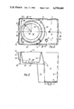
- FIG. 2 is a plan view, on a slightly larger scale, of a component
- FIGS. 3 and 4 are, respectively, sections on the lines III--III and IV--IV of FIG. 2,
- FIGS. 5 and 6 are, respectively, plan view and side view partly in section of another component
- FIG. 7 is an underneath view of a further component
- FIG. 8 is a section on the line VIII--VIII of FIG. 7, and
- FIGS. 9 and 10 are, respectively, plan and side view on a larger scale of another component.
- the apparatus shown in FIG. 1 comprises a base 1 contoured to provide an upstanding rear portion 2 and a forward ledge 3 with an inset hot plate 4 for receiving a coffee receptacle (not shown).
- FIG. 1 shows the actuating member 5 of an electric switch that controls energisation of the water heater and hot plate. It will be understood that the apparatus is powered from the mains supply of electricity.
- the upper surface of the rear portion 2 provides a surface for receiving and supporting a combined water reservoir and filter holder 6.
- the surface has spaced recesses (not shown) of inverted frusto-conical form in which locate bosses 7 integral with the base 8 of the combined reservoir-holder 6 when the latter is correctly positioned on the surface.
- screws are passed upwardly through the bases of the recesses and are screwed into the bosses 7.
- the surface is also apertured to allow penetration of an outlet pipe 9 in the base 8 and of the lower extremity 10 of a riser tube that is integral with the base 8 and extends upwardly within the combined reservoir-holder 6.
- the riser tube 11 terminates at the level of the upper edge of the combined reservoir-holder 6.
- the outlet pipe 9 is joined by a conduit (not shown) to the inlet of the electric water heater (not shown) whose outlet is joined by another conduit (not shown) to the lower extremity 10 of the riser tube 11.
- the combined reservoir-holder 6 is shown in more detail in FIGS. 2, 3 and 4. It is a one-piece moulding of a plastics material, for example SAN/polycarbonate, and comprises a reservoir 12 and a filter holder 13 located in a horizontal extension 14 of the reservoir 12. As has been explained above, the riser tube 11 is integral with the base 8 and is located in the reservoir 12.
- a plastics material for example SAN/polycarbonate
- the reservoir 12 has vertical side and rear walls 15 contoured to blend smoothly with the contours of the walls of the portion 2 of the base 1.
- Inner wall 16 of the portion 2 is concavely curved to accommodate more readily the coffee receptacle referred to above and the corresponding front wall 17 of the reservoir 12 is curved in like manner.
- Wall 17 is continued upwardly within the reservoir to form a support wall 18 for the filter holder 13 which, as can be seen from FIG. 3, is of generally cup-shaped form with a side wall 19 that extends downwardly and inwardly from the upper edge of wall 18 which is thus of frusto-conical form.
- the wall 18 is spaced from the side walls 20 of the horizontal extension 14 and from the end wall 21 of the extension.
- the extension 14 has a floor 22 that slopes downwardly away from the end wall 21 and merges into the wall 17 as can be seen from FIG. 3.
- the filter holder 13 has a base 23 integral with the side wall 19 and apertured centrally at 24 to receive an outlet boss 25.
- a slightly inset vertical flange 26 extends round the lower part of the extension 14 thereby concealing the lower portion of the holder 13.
- a spout 27 Detachably mounted on the upper end of the riser tube 11 is a spout 27 that can be swivelled on the tube to extend forwardly over the filter holder 13.
- FIGS. 5 and 6 show a filter for use with the apparatus described above and which is intended to be located within the filter holder 13.
- the filter comprises a moulded, open, one-piece framework 28 of a suitable plastics material, for example nylon, that supports a mesh filter also of a suitable plastics material, for example nylon.
- the framework 28 consists of an upper frame member 29 of annular form joined by spaced struts 30 to an imperforate disc-shaped base 31 with an upturned periphery 32.
- the struts 30 merge smoothly at each end into the frame member 29 and the base 31.
- the framework 28 is of generally cup-shaped form and is sized to fit into the holder 13.
- Short, radial downwardly-extending spacer ribs 33 are formed during moulding adjacent the junction between the lower ends of alternate ones of the struts 30 and the upturned periphery 32. When in position in the holder 13, the filter rests on the spacer ribs 33 so that the base 31 is separated by a gap from the floor 23 of the holder 13.
- the framework 28 supports the mesh filter 34 which is moulded at its edges into the frame member 29, the struts 30 and the periphery 32 of the base 31.
- the filter is located centrally of the widths of those parts.
- a handle may be provided for facilitating the entry into and removal from the holder 13 of the filter. If desired, the handle could be an integral part of the frame member 29.
- the combined reservoir holder 6 When in use the combined reservoir holder 6 is covered by a lid (not shown) which fits over the side and end walls 15, 20 and 21.
- the device Carried by the boss 25 is an anti-drip device 35 shown in FIGS. 7 and 8.
- the device is a one-piece moulding of a suitable plastics material for example that known under the Trade Mark ⁇ KEMATAL ⁇ .
- the device has a sector-shaped tongue 36 cranked as at 37 and attached by an arm 38 to part 39 of the device via lateral extensions 40 that extend outwards acting both as a hie and torsion bar.
- the arm 38 inclines downwardly from its junction with limbs 40 as can be seen from FIG. 8 and has a stiffening rib 38a.
- the arm 38 and lateral extensions 40 are separated from the remainder of part 39 of the device by gaps indicated at 41 in FIG. 7, and which terminate in a circular opening 42.
- an enlargement 43 Formed at the end of the arm 38 remote from the tongue 36 is an enlargement 43 having an upper (as seen in FIGS. 7 and 8) surface of circular form with a central projection 44. On that surface is seated a soft washer 45 of a resilient, heat-resistant material, for example silicone rubber.
- the anti-drip device 35 is attached to the boss 25 by pressing the latter into the opening 42 which is slightly undersized to provide a force fit on to the boss.
- the valve washer 45 closes the opening in the boss 25.
- the boss 25 may have an external circumferential groove into which the edge of the part 39 round the opening 42 is pressed.
- the apparatus is used in the well-known manner.
- the filter is placed in the holder 13, the ribs 33 resting on the base 23 thereby providing a slight gap between the base 23 and the base 31 of the filter.
- the reservoir 12 is then filled with water and the required amount of ground coffee placed in the base 23 of the filter.
- a coffee receptacle is then placed underneath the filter holder 13, the receptacle resting on the hot plate 4. As the receptacle is inserted beneath the filter holder, the edge of the receptacle contacts the tongue 36 and pivots the latter upwardly. Upward pivotal movement of the tongue 36 about the transverse limbs 40 stresses the latter and also causes the ends of the limbs 38 remote from the tongue 36 to move downwardly carrying the valve washer 45 away from the opening in the boss 25.
- control member 5 By actuating control member 5, the electric heater and hot plate are energised and after a few minutes hot water feeds up riser tube 11 and passes via spout 27 into the filter and over the ground coffee therein.
- the water level in the filter slowly rises and quickly reaches a point where it flows through the mesh filter 34, downwards between the filter and the wall 19, into the gap between the base 31 of the filter and the base 23 of the filter holder 13 and out through the opening in the boss 25 and into the coffee receptacle now being warmed by the hot plate 4.
- the rate of flow of hot water into the filter is calculated to give the hot water a residence time in the filter sufficient to produce a satisfactory infusion of coffee into the water.
- the coffee has to steep in it for a short period until the water level builds up sufficiently to overcome surface tension effects and allow the water to discharge through the mesh filter. Because the base 31 of the filter is imperforate hot water cannot trickle directly through the coffee but must flow sideways through the mesh filter as just described.
- the receptacle When the water content of the reservoir has flowed into the filter, the receptacle is removed so that a user can pour coffee in the receptacle into cups. Removal of the receptacle allows the stressed limbs 40 to restore and this seats the washer 45 on the boss 25 thereby closing the opening therein and preventing coffee dripping on to the hot plate 4.
- the tongue 36 also returns to its initial position.
- the apparatus After use, the apparatus is extremely easy to clean.
- the filter can be lifted out using the handle, if provided, and after the coffee grounds have been emptied out the mesh filter can be cleaned by rinsing under running water.
- the filter holder can also be rinsed out and wiped clean, the smooth surface of the wall 19 and base 23 making cleaning very simple.
- a filter as just described improves the taste of the coffee. As the filter is re-usable after being cleaned, it is cheaper in the long term, than conventional filter papers that are not re-usuable. In addition, the filter eliminates the need to include a flow control in the coffee filter machine because the coffee is automatically infused correctly.
- extension 14 increases the capacity of the reservoir 12 as compared with conventional forms of apparatus, the sloping floor 22 ensuring that all the water in the extension runs back into the reservoir 12.
- the combining of the filter holder and reservoir into a single component reduces manufacturing and handling and assembly costs as compared with conventional forms of apparatus.
- the filter described above could be replaced by a so-called "cup-cake" filter paper in cases where finer filtering is required.
- a filter paper requires the use of a spacer to hold the base of the filter away from the base 23 of the filter holder and a suitable form of spacer is shown in FIGS. 9 and 10.
- the spacer comprises a moulded frame of a suitable plastics material, for example polypropylene having a central annulus 46 from the lower edge of which extend a number of spaced radial arms 47 that taper outwards from the central annulus 46.
- a suitable plastics material for example polypropylene having a central annulus 46 from the lower edge of which extend a number of spaced radial arms 47 that taper outwards from the central annulus 46.
- the "cup-cake” filter paper has convoluted or folded side walls and is placed in the filter holder with the base of the paper seated upon the spacer which itself rests on the base 23 of the filter holder.
- the spacer ensures that the base of the filter paper is spaced from the base 23 by a gap through which the filtered coffee flows.
- the convoluted or folded walls provide passages through which the coffee reaches that gap.
- the filter paper carrying the coffee grounds is removed.
- the spacer can then be taken out of the holder and washed easily as can the inside of the holder itself.
- riser tube 11 integrally with the combined reservoir-holder but it is preferred to do so.
- a separate riser tube plugged into the base 8 of the reservoir could be used.
Landscapes
- Engineering & Computer Science (AREA)
- Food Science & Technology (AREA)
- Apparatus For Making Beverages (AREA)
Applications Claiming Priority (2)
| Application Number | Priority Date | Filing Date | Title |
|---|---|---|---|
| GB08307018A GB2137075B (en) | 1983-03-15 | 1983-03-15 | Apparatus for making hot drinks |
| GB8307018 | 1983-03-15 |
Publications (1)
| Publication Number | Publication Date |
|---|---|
| US4558640A true US4558640A (en) | 1985-12-17 |
Family
ID=10539559
Family Applications (1)
| Application Number | Title | Priority Date | Filing Date |
|---|---|---|---|
| US06/589,696 Expired - Fee Related US4558640A (en) | 1983-03-15 | 1984-03-13 | Apparatus for making hot drinks |
Country Status (3)
| Country | Link |
|---|---|
| US (1) | US4558640A (fr) |
| CA (1) | CA1213744A (fr) |
| GB (1) | GB2137075B (fr) |
Cited By (10)
| Publication number | Priority date | Publication date | Assignee | Title |
|---|---|---|---|---|
| US5060558A (en) * | 1989-02-14 | 1991-10-29 | Robert Krups Stiftung & Co. Kg. | Machine for brewing coffee, tea and the like |
| US5616242A (en) * | 1995-05-26 | 1997-04-01 | Mandola; Mary D. | Two stage bottle filter for the removal of sediment |
| US6269735B1 (en) * | 2000-05-01 | 2001-08-07 | Patrick J. Rolfes | Liquid detectable watertight coffee brewer enclosure |
| WO2002049488A1 (fr) * | 2000-12-20 | 2002-06-27 | Koninklijke Philips Electronics N.V. | Machine a cafe |
| WO2003089829A1 (fr) | 2002-04-18 | 2003-10-30 | Parker Hannifin Corporation | Ensemble tuyau |
| US20050145112A1 (en) * | 2004-01-06 | 2005-07-07 | Paul Scribner | Top load coffee maker with front access water reservoir |
| USD546112S1 (en) * | 2006-01-23 | 2007-07-10 | Sunbeam Products, Inc. | Coffeemaker |
| US8616118B1 (en) * | 2009-09-28 | 2013-12-31 | Food Equipment Technologies Company, Inc. | Brewer with brew basket having electromagnetic drain hole closure |
| USD775887S1 (en) * | 2015-03-06 | 2017-01-10 | Spectrum Brands, Inc. | Coffee maker |
| USD786603S1 (en) * | 2016-06-29 | 2017-05-16 | Sunbeam Products, Inc. | Hot beverage maker |
Families Citing this family (3)
| Publication number | Priority date | Publication date | Assignee | Title |
|---|---|---|---|---|
| NL8401031A (nl) * | 1984-04-02 | 1985-11-01 | Philips Nv | Koffiezetapparaat. |
| FR2783684B1 (fr) | 1998-09-25 | 2000-11-24 | Seb Sa | Cafetiere a chaudiere |
| IT1395827B1 (it) * | 2009-04-09 | 2012-10-26 | Saeco Strategic Services Ltd | "macchina a percolazione per la produzione di bevande" |
Citations (7)
| Publication number | Priority date | Publication date | Assignee | Title |
|---|---|---|---|---|
| GB1262430A (en) * | 1969-03-04 | 1972-02-02 | Sperry Rand Corp | Automatic infusion brew maker |
| US3718084A (en) * | 1971-11-09 | 1973-02-27 | Mc Graw Edison Co | Coffee maker basket and filter |
| GB1329821A (en) * | 1969-10-09 | 1973-09-12 | Gjc Dev Ltd | Beverage making apparatus |
| DE2531811A1 (de) * | 1975-07-16 | 1977-01-20 | Bosch Siemens Hausgeraete | Anzeigevorrichtung fuer den verkalkungsgrad von elektrischen hausgeraeten |
| GB2009590A (en) * | 1977-11-30 | 1979-06-20 | Tokyo Shibaura Electric Co | Coffee-pot and coffee-mill combination |
| US4331067A (en) * | 1980-12-22 | 1982-05-25 | Sunbeam Corporation | Coffeemaker |
| GB2098857A (en) * | 1981-02-25 | 1982-12-01 | Raytheon Co | Microwave expresso coffee maker |
Family Cites Families (1)
| Publication number | Priority date | Publication date | Assignee | Title |
|---|---|---|---|---|
| GB1119891A (en) * | 1965-09-10 | 1968-07-17 | Sanvitale Salvatore | A coffee pot for brewing coffee |
-
1983
- 1983-03-15 GB GB08307018A patent/GB2137075B/en not_active Expired
-
1984
- 1984-03-13 US US06/589,696 patent/US4558640A/en not_active Expired - Fee Related
- 1984-03-14 CA CA000449595A patent/CA1213744A/fr not_active Expired
Patent Citations (8)
| Publication number | Priority date | Publication date | Assignee | Title |
|---|---|---|---|---|
| GB1262430A (en) * | 1969-03-04 | 1972-02-02 | Sperry Rand Corp | Automatic infusion brew maker |
| GB1329821A (en) * | 1969-10-09 | 1973-09-12 | Gjc Dev Ltd | Beverage making apparatus |
| US3718084A (en) * | 1971-11-09 | 1973-02-27 | Mc Graw Edison Co | Coffee maker basket and filter |
| DE2531811A1 (de) * | 1975-07-16 | 1977-01-20 | Bosch Siemens Hausgeraete | Anzeigevorrichtung fuer den verkalkungsgrad von elektrischen hausgeraeten |
| GB2009590A (en) * | 1977-11-30 | 1979-06-20 | Tokyo Shibaura Electric Co | Coffee-pot and coffee-mill combination |
| US4331067A (en) * | 1980-12-22 | 1982-05-25 | Sunbeam Corporation | Coffeemaker |
| GB2089650A (en) * | 1980-12-22 | 1982-06-30 | Sunbeam Corp | Coffee making apparatus |
| GB2098857A (en) * | 1981-02-25 | 1982-12-01 | Raytheon Co | Microwave expresso coffee maker |
Cited By (11)
| Publication number | Priority date | Publication date | Assignee | Title |
|---|---|---|---|---|
| US5060558A (en) * | 1989-02-14 | 1991-10-29 | Robert Krups Stiftung & Co. Kg. | Machine for brewing coffee, tea and the like |
| US5616242A (en) * | 1995-05-26 | 1997-04-01 | Mandola; Mary D. | Two stage bottle filter for the removal of sediment |
| US6269735B1 (en) * | 2000-05-01 | 2001-08-07 | Patrick J. Rolfes | Liquid detectable watertight coffee brewer enclosure |
| WO2002049488A1 (fr) * | 2000-12-20 | 2002-06-27 | Koninklijke Philips Electronics N.V. | Machine a cafe |
| WO2003089829A1 (fr) | 2002-04-18 | 2003-10-30 | Parker Hannifin Corporation | Ensemble tuyau |
| US20050145112A1 (en) * | 2004-01-06 | 2005-07-07 | Paul Scribner | Top load coffee maker with front access water reservoir |
| US7146904B2 (en) * | 2004-01-06 | 2006-12-12 | Whirlpool Corporation | Top load coffee maker with front access water reservoir |
| USD546112S1 (en) * | 2006-01-23 | 2007-07-10 | Sunbeam Products, Inc. | Coffeemaker |
| US8616118B1 (en) * | 2009-09-28 | 2013-12-31 | Food Equipment Technologies Company, Inc. | Brewer with brew basket having electromagnetic drain hole closure |
| USD775887S1 (en) * | 2015-03-06 | 2017-01-10 | Spectrum Brands, Inc. | Coffee maker |
| USD786603S1 (en) * | 2016-06-29 | 2017-05-16 | Sunbeam Products, Inc. | Hot beverage maker |
Also Published As
| Publication number | Publication date |
|---|---|
| CA1213744A (fr) | 1986-11-12 |
| GB2137075B (en) | 1986-09-10 |
| GB2137075A (en) | 1984-10-03 |
| GB8307018D0 (en) | 1983-04-20 |
Similar Documents
| Publication | Publication Date | Title |
|---|---|---|
| US4558640A (en) | Apparatus for making hot drinks | |
| US4986172A (en) | Beverage brewing apparatus | |
| CA2456973C (fr) | Distributeur de boisson avec ensemble ramasse-gouttes et procede associe | |
| US6843165B2 (en) | Coffee brewer | |
| CA2292813C (fr) | Appareil pour infuser le the | |
| US5125327A (en) | Beverage pot | |
| US6283013B1 (en) | Tea steeper for coffeemaker | |
| US6681960B2 (en) | Hot beverage maker with cup-actuated dispenser | |
| US4802406A (en) | Coffeemaker | |
| US4911067A (en) | Infusion beverage maker | |
| US20120052171A1 (en) | High powered, single serve, automatic drip brewed beverage maker and related scoop | |
| US6571686B1 (en) | Brew basket with overflow channel | |
| US5190652A (en) | Filter holder for coffee cartridges | |
| US3320073A (en) | Means for brewing coffee | |
| US5470011A (en) | Beverage dispensing urn and drip collector device | |
| US20140302210A1 (en) | Hot Beverage Maker with Dispenser | |
| US4683812A (en) | Tea brewer and dispenser combination | |
| US7461586B2 (en) | Hot beverage maker with cup-actuated, low-drip dispenser | |
| US4027582A (en) | Art of brewing individual servings of coffee in a cup | |
| US7063005B1 (en) | Automatic coffee maker with grinder | |
| FR2713072B1 (fr) | Porte-Filtre. | |
| US5619904A (en) | Automatic tea brewing device and tea pot receptacle | |
| US4749107A (en) | Beverage reservoir with overflow passageway in the handle | |
| FR2953112A1 (fr) | Appareil de preparation de boissons infusees avec reserve amovible | |
| WO1996033643A1 (fr) | Dispositif automatique d'infusion de the et theiere |
Legal Events
| Date | Code | Title | Description |
|---|---|---|---|
| AS | Assignment |
Owner name: TI RUSSELL HOBBS LIMITED P.O. BOX 1, GRINDLEY LANE Free format text: ASSIGNMENT OF ASSIGNORS INTEREST.;ASSIGNOR:MARCHANT, DAVID J.;REEL/FRAME:004240/0110 Effective date: 19840305 |
|
| FEPP | Fee payment procedure |
Free format text: PAYOR NUMBER ASSIGNED (ORIGINAL EVENT CODE: ASPN); ENTITY STATUS OF PATENT OWNER: LARGE ENTITY |
|
| FPAY | Fee payment |
Year of fee payment: 4 |
|
| REMI | Maintenance fee reminder mailed | ||
| LAPS | Lapse for failure to pay maintenance fees | ||
| FP | Lapsed due to failure to pay maintenance fee |
Effective date: 19931219 |
|
| STCH | Information on status: patent discontinuation |
Free format text: PATENT EXPIRED DUE TO NONPAYMENT OF MAINTENANCE FEES UNDER 37 CFR 1.362 |