US4560331A - Lubricant reservoir - Google Patents
Lubricant reservoir Download PDFInfo
- Publication number
- US4560331A US4560331A US06/668,651 US66865184A US4560331A US 4560331 A US4560331 A US 4560331A US 66865184 A US66865184 A US 66865184A US 4560331 A US4560331 A US 4560331A
- Authority
- US
- United States
- Prior art keywords
- lubricant
- reservoir
- weir
- bearing
- inlet
- Prior art date
- Legal status (The legal status is an assumption and is not a legal conclusion. Google has not performed a legal analysis and makes no representation as to the accuracy of the status listed.)
- Expired - Fee Related
Links
- 239000000314 lubricant Substances 0.000 title claims abstract description 64
- 230000002093 peripheral effect Effects 0.000 claims abstract description 10
- 230000005484 gravity Effects 0.000 claims abstract description 6
- 238000010276 construction Methods 0.000 description 5
- 238000005086 pumping Methods 0.000 description 3
- 230000000694 effects Effects 0.000 description 2
- 238000005461 lubrication Methods 0.000 description 2
- 229910001361 White metal Inorganic materials 0.000 description 1
- 239000010969 white metal Substances 0.000 description 1
Images

Classifications
-
- F—MECHANICAL ENGINEERING; LIGHTING; HEATING; WEAPONS; BLASTING
- F16—ENGINEERING ELEMENTS AND UNITS; GENERAL MEASURES FOR PRODUCING AND MAINTAINING EFFECTIVE FUNCTIONING OF MACHINES OR INSTALLATIONS; THERMAL INSULATION IN GENERAL
- F16N—LUBRICATING
- F16N19/00—Lubricant containers for use in lubricators or lubrication systems
-
- F—MECHANICAL ENGINEERING; LIGHTING; HEATING; WEAPONS; BLASTING
- F16—ENGINEERING ELEMENTS AND UNITS; GENERAL MEASURES FOR PRODUCING AND MAINTAINING EFFECTIVE FUNCTIONING OF MACHINES OR INSTALLATIONS; THERMAL INSULATION IN GENERAL
- F16N—LUBRICATING
- F16N7/00—Arrangements for supplying oil or unspecified lubricant from a stationary reservoir or the equivalent in or on the machine or member to be lubricated
- F16N7/02—Arrangements for supplying oil or unspecified lubricant from a stationary reservoir or the equivalent in or on the machine or member to be lubricated with gravity feed or drip lubrication
Definitions
- the present invention relates to a reservoir for gravity feeding lubricant to a bearing.
- a bearing particularly a heavy duty bearing, in which lubrication is effected by lubricant being picked up on a disc mounted on the bearing shaft, the disc having, at its periphery, an axially extending ring on the inner and outer surface of which the lubricant forms a film.
- lubricant on the outer surface is scraped of by an external scraper and falls under gravity on to the bearing surface and, as the speed increases, lubricant on the inner surfaces is picked up by the scoop to produce a pressure head sufficient to pump the lubricant to a reservoir from which it flows to the bearing surface under gravity.
- the lubricant is pumped to the reservoir through an external cooler and an external filter.
- Such a construction is very satisfactory and substantially reduces the cost as compared with known bearings and yet allows one to provide a cooler and a filter without the necessity for a separate pump.
- One problem does arise when the bearing is used to run at low speeds. It has been found that with the lower sump of the bearing full of oil, the performance of the pump is reduced to such an extent that the bearing is capable of using more oil than the pump (provided by the disc and the scoop) could deliver.
- a reservoir for gravity feeding lubricant to a bearing said reservoir comprising a receptacle having a peripheral wall, a lower outlet from said receptacle for the outflow of lubricant, an annular weir surrounding an inner space around said lower outlet, an inlet positioned to feed lubricant into the outer space between said peripheral wall and said annular weir and a bleed passage in said annular weir permitting a limited amount of lubricant to flow between said outer and inner spaces, a greater flow of lubricant taking place when the lubricant can pass over said weir.
- the outlet is formed actually in the bottom wall of the receptacle.
- the bleed passage may be in the form of an aperture, of a size designed to meet the particular requirements of the bearing, through the annular wall adjacent to the bottom wall of the receptacle.
- the annular weir is positioned sufficiently close to the inlet for lubricant to pass directly from the inlet into the inner space, when a full flow of luricant is taking place.
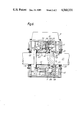
- FIG. 1 is a plan view of one embodiment of reservoir according to the present invention.
- FIG. 2 is a section taken along the line II, II of FIG. 1;
- FIG. 3 is a section along the line III, III of FIG. 1;
- FIG. 4 is a view similar to the right hand portion of FIG. 2 showing a full flow of lubricant
- FIG. 5 is a view similar to FIG. 4 showing a low flow rate of lubricant.
- FIG. 6 is a cross-section through one embodiment of bearing as illustrated in European Patent 0073281A.
- the reservoir illustrated in the drawings comprises a receptacle 10 having a peripheral wall 11 and a bottom wall 12, the reservoir illustrated being of generally square shape as viewed in plan.
- a cover 14 is shown in FIG. 2, but has been omitted in FIG. 1 for the sake of clarity.
- An inlet 16 for lubricant is provided on the right hand side as seen in FIG. 2 and a similar inlet 17 is shown on the left hand side but will normally be blocked off.
- Formed in the bottom wall 12 is an outlet 18 and this is surrounded by an annular weir 20 consisting of a front wall 22 a rear wall 24 and two side walls 26 which are slightly lower than the front and rear walls.
- a bleed orifice 28 is formed in the rear wall and connects the outer space 30 formed outside the annular weir 20 with the inner space 32 surrounded by the annular weir and from which the outlet 18 opens.
- the lubricant 40 flows in as shown in FIG. 5 at a relatively low rate and falls outside the annular weir 26 into the outer space 30. It can then flow through the relatively small bleed passage 28 into the inner space 32 from which it can flow out through the outlet 18 to a bearing as illustrated, for example, in European Patent 0073281A.
- FIG. 6 illustrates the bearing of that Patent and the following is a portion of the description thereof to which 100 has been added to the reference numerals.
- the bearing comprises a lower casing half 110 having bolted thereon an upper casing 111 surmounted by the lubricant reservoir 10.
- Mounted on the casing parts are lower and upper outer fixed parts or keeps 113 and 117 of the bearing, these having part-spherical inner surfaces 115 and 116 which cooperate with part-spherical surfaces on shell halves 117 and 118.
- the inner surfaces of the shell halves have conventional white metal bearing shells 119 and 120 forming bearing surfaces for the shaft 121 which has radially extending rims 122 and 123, thus providing a self-aligning bearing of a conventional type.
- the right hand surface of the rim 123 has a central annular recess 124 formed therein in which is located the two radially inner hub parts 125, 126 of disc halves 127 and 128 respectively. These disc parts are secured by bolts 129 which extend through the hub parts 125, 126 and into the rim 123.
- the recess 124 leaves a peripheral rib 130 into which the hub parts 125 and 126 are snugly engaged to reduce any tendency for the disc parts to fly out during high speed operation.
- the bearing is provided with seals 131 and 132 held in place by seal plates 133 and 134.
- the disc 128 carries an axially inwardly extending ring 135 having a lip 136 at its inner axial end.
- the shell 118 carries, on the side of the keep 114 facing the disc 128, a support member 137 which carries a scoop assembly 138 which extends within the ring 135.
- This scoop assembly includes two oppositely curved scrolls which have their axes substantially parallel to the axis of the shaft 121.
- the scrolls include wall portions radially spaced from the outermost part of the scroll to provide two oppositely directed mouths.
- the two channels formed between the outermost part of each scroll and the wall portions are of increasing cross-section as they lead away from the mouth.
- the member 136 has a transverse bore 146 therein which accommodates a valve ball, extreme positions of which are determined by stoppers located in longitudinal bores in the member 136 and communicating with the interior of the scrolls.
- the transverse passage 146 connects directly to a closed conduit 152 which leads, via a bore 153 provided with O-ring 154, to a duct 155 in the keep 114. This duct leads out of a side of the bearing and communicates with an outlet pipe.
- a scraper 157 which rubs on the external surface of the ring 135 to scrape the lubricant therefrom.
- the lubricant so scraped is led to an aperture 158 in the member 137 and thence into a trough 159 and finally via radial bores 160 to the bearing surface 120.
Landscapes
- Engineering & Computer Science (AREA)
- General Engineering & Computer Science (AREA)
- Mechanical Engineering (AREA)
- Sliding-Contact Bearings (AREA)
- Rolling Contact Bearings (AREA)
Applications Claiming Priority (2)
| Application Number | Priority Date | Filing Date | Title |
|---|---|---|---|
| GB08329688A GB2149460B (en) | 1983-11-07 | 1983-11-07 | Lubricant reservoir |
| GB8329688 | 1983-11-07 |
Publications (1)
| Publication Number | Publication Date |
|---|---|
| US4560331A true US4560331A (en) | 1985-12-24 |
Family
ID=10551371
Family Applications (1)
| Application Number | Title | Priority Date | Filing Date |
|---|---|---|---|
| US06/668,651 Expired - Fee Related US4560331A (en) | 1983-11-07 | 1984-11-06 | Lubricant reservoir |
Country Status (6)
| Country | Link |
|---|---|
| US (1) | US4560331A (fr) |
| EP (1) | EP0141573A3 (fr) |
| AU (1) | AU3448984A (fr) |
| GB (1) | GB2149460B (fr) |
| IN (1) | IN161973B (fr) |
| ZA (1) | ZA848537B (fr) |
Cited By (3)
| Publication number | Priority date | Publication date | Assignee | Title |
|---|---|---|---|---|
| US20060231337A1 (en) * | 2005-04-11 | 2006-10-19 | The Falk Corporation | Elevated oil reservoir collection and distribution system |
| US10578172B2 (en) | 2015-12-03 | 2020-03-03 | Horton, Inc. | Viscous clutch fluid capture system |
| US11441621B2 (en) | 2019-01-31 | 2022-09-13 | Horton, Inc. | Pump and wiper assembly, associated viscous clutch and associated method |
Families Citing this family (1)
| Publication number | Priority date | Publication date | Assignee | Title |
|---|---|---|---|---|
| SE503928C2 (sv) * | 1994-12-28 | 1996-09-30 | Tetra Laval Holdings & Finance | Anordning för fördelning av smörjmedel till olika smörjställen samt en pumpanordning med en sådan fördelningsanordning |
Citations (2)
| Publication number | Priority date | Publication date | Assignee | Title |
|---|---|---|---|---|
| US1901749A (en) * | 1930-08-26 | 1933-03-14 | Johnson Albert | Valve controlling means for fluid distributing devices |
| US2965198A (en) * | 1960-03-07 | 1960-12-20 | Wesson Cutting Tools Ltd | Intermittent oiler |
Family Cites Families (4)
| Publication number | Priority date | Publication date | Assignee | Title |
|---|---|---|---|---|
| DE302183C (fr) * | ||||
| FR795381A (fr) * | 1934-09-27 | 1936-03-12 | Appareil pour débiter un lubrifiant ou fluide analogue en quantités réglées | |
| FR984987A (fr) * | 1943-10-22 | 1951-07-12 | Graisseur à huile | |
| ATE12136T1 (de) * | 1981-08-28 | 1985-03-15 | Howden James & Co Ltd | Lager. |
-
1983
- 1983-11-07 GB GB08329688A patent/GB2149460B/en not_active Expired
-
1984
- 1984-10-16 EP EP84307096A patent/EP0141573A3/fr not_active Withdrawn
- 1984-10-17 IN IN806/DEL/84A patent/IN161973B/en unknown
- 1984-10-19 AU AU34489/84A patent/AU3448984A/en not_active Abandoned
- 1984-11-01 ZA ZA848537A patent/ZA848537B/xx unknown
- 1984-11-06 US US06/668,651 patent/US4560331A/en not_active Expired - Fee Related
Patent Citations (2)
| Publication number | Priority date | Publication date | Assignee | Title |
|---|---|---|---|---|
| US1901749A (en) * | 1930-08-26 | 1933-03-14 | Johnson Albert | Valve controlling means for fluid distributing devices |
| US2965198A (en) * | 1960-03-07 | 1960-12-20 | Wesson Cutting Tools Ltd | Intermittent oiler |
Cited By (4)
| Publication number | Priority date | Publication date | Assignee | Title |
|---|---|---|---|---|
| US20060231337A1 (en) * | 2005-04-11 | 2006-10-19 | The Falk Corporation | Elevated oil reservoir collection and distribution system |
| US10578172B2 (en) | 2015-12-03 | 2020-03-03 | Horton, Inc. | Viscous clutch fluid capture system |
| US10612605B2 (en) | 2015-12-03 | 2020-04-07 | Horton, Inc. | Viscous clutch fluid capture system |
| US11441621B2 (en) | 2019-01-31 | 2022-09-13 | Horton, Inc. | Pump and wiper assembly, associated viscous clutch and associated method |
Also Published As
| Publication number | Publication date |
|---|---|
| EP0141573A3 (fr) | 1986-06-11 |
| ZA848537B (en) | 1985-06-26 |
| GB8329688D0 (en) | 1983-12-07 |
| AU3448984A (en) | 1985-05-16 |
| EP0141573A2 (fr) | 1985-05-15 |
| GB2149460A (en) | 1985-06-12 |
| GB2149460B (en) | 1986-12-10 |
| IN161973B (fr) | 1988-03-05 |
Similar Documents
| Publication | Publication Date | Title |
|---|---|---|
| US4576001A (en) | Gas turbine engine oil systems | |
| US3785458A (en) | Lubrication system for a gear drive mechanism | |
| US4714139A (en) | Lubricating system for gas turbine engines and pump for such a system | |
| JPS6242186B2 (fr) | ||
| US4448552A (en) | Bearing lubrication system | |
| US4271717A (en) | Axle assemblies | |
| US3664461A (en) | Oil pump for a motor compressor | |
| GB2026612A (en) | Rotary positive-displacement fluid-machines | |
| US5150769A (en) | Controlled-flow lubricating system | |
| US5336048A (en) | Fluid directing device for seal chamber | |
| US4245952A (en) | Pump | |
| US5467667A (en) | Epicyclic change-speed gearbox casing with a spiral partition wall | |
| US4560331A (en) | Lubricant reservoir | |
| CN102256709A (zh) | 带有润滑装置的离心分离器 | |
| US5435133A (en) | Hydrodynamic clutch | |
| US4683984A (en) | Scavenge oil system | |
| CN120212078A (zh) | 双吸泵用轴承润滑油室结构 | |
| US2332614A (en) | Means for lubricating internal bearings in centrifugal gas pumps | |
| US2805819A (en) | Turbine driven blowers or pumps | |
| JPS59215920A (ja) | 排ガスタ−ボ過給機の自動吸込式の遠心−潤滑オイルポンプ | |
| EP0562094A1 (fr) | Systeme de lubrification situe dans un dispositif de support de roue dont le moyeu est monte rotatif sur une fusee d'essieu. | |
| JPS62118198A (ja) | 潤滑剤用の遠心円板 | |
| US3091183A (en) | Centrifugal pump | |
| US3115844A (en) | Jet pump improvement | |
| EP0141574A2 (fr) | Cuillère de manipulation de graisse |
Legal Events
| Date | Code | Title | Description |
|---|---|---|---|
| AS | Assignment |
Owner name: JAMES HOWDEN & COMPANY LIMITED 195 SCOTLAND STREET Free format text: ASSIGNMENT OF ASSIGNORS INTEREST.;ASSIGNOR:SANDERSON, GEORGE F.;REEL/FRAME:004333/0986 Effective date: 19841022 |
|
| REMI | Maintenance fee reminder mailed | ||
| LAPS | Lapse for failure to pay maintenance fees | ||
| STCH | Information on status: patent discontinuation |
Free format text: PATENT EXPIRED DUE TO NONPAYMENT OF MAINTENANCE FEES UNDER 37 CFR 1.362 |
|
| FP | Lapsed due to failure to pay maintenance fee |
Effective date: 19891222 |