US4565347A - Monolithic precast invert system - Google Patents
Monolithic precast invert system Download PDFInfo
- Publication number
- US4565347A US4565347A US06/515,130 US51513083A US4565347A US 4565347 A US4565347 A US 4565347A US 51513083 A US51513083 A US 51513083A US 4565347 A US4565347 A US 4565347A
- Authority
- US
- United States
- Prior art keywords
- invert
- forming
- forming section
- section
- swingable
- Prior art date
- Legal status (The legal status is an assumption and is not a legal conclusion. Google has not performed a legal analysis and makes no representation as to the accuracy of the status listed.)
- Expired - Lifetime
Links
- 238000005266 casting Methods 0.000 claims description 29
- 230000000712 assembly Effects 0.000 claims description 9
- 238000000429 assembly Methods 0.000 claims description 9
- 238000003780 insertion Methods 0.000 claims description 3
- 230000037431 insertion Effects 0.000 claims description 3
- 210000003127 knee Anatomy 0.000 abstract description 3
- 239000000463 material Substances 0.000 description 12
- 238000000034 method Methods 0.000 description 5
- 210000002414 leg Anatomy 0.000 description 3
- 230000003014 reinforcing effect Effects 0.000 description 3
- 230000001154 acute effect Effects 0.000 description 2
- 238000000465 moulding Methods 0.000 description 2
- 230000008878 coupling Effects 0.000 description 1
- 238000010168 coupling process Methods 0.000 description 1
- 238000005859 coupling reaction Methods 0.000 description 1
- 230000005484 gravity Effects 0.000 description 1
- 238000009434 installation Methods 0.000 description 1
- 239000007788 liquid Substances 0.000 description 1
- 239000000314 lubricant Substances 0.000 description 1
- 230000004048 modification Effects 0.000 description 1
- 238000012986 modification Methods 0.000 description 1
- 230000002787 reinforcement Effects 0.000 description 1
- 239000007787 solid Substances 0.000 description 1
- 238000006467 substitution reaction Methods 0.000 description 1
- 230000007704 transition Effects 0.000 description 1
Images


Classifications
-
- E—FIXED CONSTRUCTIONS
- E03—WATER SUPPLY; SEWERAGE
- E03F—SEWERS; CESSPOOLS
- E03F5/00—Sewerage structures
- E03F5/02—Manhole shafts or other inspection chambers; Snow-filling openings; accessories
- E03F5/021—Connection of sewer pipes to manhole shaft
-
- B—PERFORMING OPERATIONS; TRANSPORTING
- B28—WORKING CEMENT, CLAY, OR STONE
- B28B—SHAPING CLAY OR OTHER CERAMIC COMPOSITIONS; SHAPING SLAG; SHAPING MIXTURES CONTAINING CEMENTITIOUS MATERIAL, e.g. PLASTER
- B28B7/00—Moulds; Cores; Mandrels
- B28B7/02—Moulds with adjustable parts specially for modifying at will the dimensions or form of the moulded article
- B28B7/04—Moulds with adjustable parts specially for modifying at will the dimensions or form of the moulded article one or more of the parts being pivotally mounted
-
- B—PERFORMING OPERATIONS; TRANSPORTING
- B28—WORKING CEMENT, CLAY, OR STONE
- B28B—SHAPING CLAY OR OTHER CERAMIC COMPOSITIONS; SHAPING SLAG; SHAPING MIXTURES CONTAINING CEMENTITIOUS MATERIAL, e.g. PLASTER
- B28B7/00—Moulds; Cores; Mandrels
- B28B7/16—Moulds for making shaped articles with cavities or holes open to the surface, e.g. with blind holes
- B28B7/168—Moulds for making shaped articles with cavities or holes open to the surface, e.g. with blind holes for holders or similar hollow articles, e.g. vaults, sewer pits
-
- E—FIXED CONSTRUCTIONS
- E03—WATER SUPPLY; SEWERAGE
- E03F—SEWERS; CESSPOOLS
- E03F5/00—Sewerage structures
- E03F5/02—Manhole shafts or other inspection chambers; Snow-filling openings; accessories
-
- E—FIXED CONSTRUCTIONS
- E03—WATER SUPPLY; SEWERAGE
- E03F—SEWERS; CESSPOOLS
- E03F5/00—Sewerage structures
- E03F5/02—Manhole shafts or other inspection chambers; Snow-filling openings; accessories
- E03F2005/028—Sealing joints between manhole segments
Definitions
- the present invention relates to manhole structures and more particularly to system and method for forming an invert in a manhole base with a single casting operation through the use of an invert forming mold section adapted to form an invert having one of a variety of angular configurations.
- Manhole structures are typically cast at the factory using the mold forms appropriate for forming each section.
- Manhole bases are cast using concentric inner and outer mold forms which define the walls of the manhole base.
- the manhole base is cast "upside down".
- the top member of the inner mold is typically provided with raised projections which define the invert to be formed in the manhole base. Since a variety of inverts can be formed, such as, for example, a straight-through invert, an acute angle invert, a right angle invert, and a Y-shaped invert, to name just a few possible arrangements, a separate top section is required for each invert configuration.
- One technique for forming a monolithic manhole base in a single pour operation is described in copending application Ser. No. 234,639 filed Feb.
- the present invention is characterized by comprising the top member for the inner mold of a manhole base casting assembly utilized to cast a manhole base, said top member having a fixed invert forming section and at least one movable invert forming section joined to an arm whose inner end is swingably mounted upon a centrally located pivot to permit the movable invert forming section (or sections) to be moved to the desired location.
- Positioning openings are arranged at regular angular intervals about the periphery of the top member and are adapted to receive a downwardly extending pin provided in the movable invert forming section (or sections) to simply and yet positively and accurately locate the movable forming section during casting.
- the central knee portion is positioned between the spaced inner ends of the fixed and movable invert forming sections and has a generally semi-cylindrical hollow configuration in order to smoothly mate with the inner ends of the fixed and movable invert forming sections to form an invert having a smooth transitional curvature moving from one invert forming section to the other.
- the apparatus of the present invention provides a casting system which is simple to use and which is capable of forming a wide variety of inverts reducing the number of components and hence the cost of a monolithic casting system as well as simplifying the casting operation.
- Still another object of the present invention is to provide apparatus of the character described hereinabove in which curved hollow inserts are arranged between the inner ends of fixed and movable invert forming sections to fill the region therebetween and thereby provide a smooth curved transition from each invert section within the base member formed during the casting operation.
- Still another object of the present invention is to provide a casting method and apparatus of the character described in which the inner mold top member may be provided with more than one movable invert forming section.
- FIG. 1 shows an exploded perspective view of a monolithic casting system embodying the principles of the present invention.
- FIG. 2 is a top plan view of the inner mold employed in the system of FIG. 1.
- FIG. 2a shows an end view portion of FIG. 2 looking in the direction of arrows 2a--2a.
- FIG. 3 shows a sectional elevational view of the assembly of FIG. 1.
- FIGS. 4a through 4c show perspective views of several center inserts selectively employed in the casting system of FIG. 1.
- FIG. 5 shows a sectional view of a manhole base cast by using the apparatus of FIG. 1.
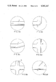
- FIGS. 6a through 6f show top plan views of some typical invert combinations.
- FIG. 1 shows an exploded perspective view of the molding apparatus 10 employed for forming a manhole base in accordance with the single-pour technique.
- Apparatus 10 is comprised of a disc-shaped member 22 having an outermost vertically aligned periphery 22a adapted to be received within the interior of the lower edge of side wall 12a of the outer cylindrical mold member 12.
- the bottom edge 12a of member 12 is adapted to rest upon surface 22b.
- Member 12 defines the exterior wall of the manhole base which is cast "upside down" as will be described in detail hereinbelow.
- Member 12 is provided with a pair of collars 15, 15 swingably mounted to the exterior of member 12 by fastening pins 13, 13.
- Collars 15, 15 are each provided with a short section of chain 15a, 15a for receiving hooks (not shown) from an overhead crane, for example, for lifting and rotating the molding apparatus 10, as will be more fully described.
- Cylindrical shaped inner mold member 18 is provided with a hinge assembly 27 for respectively increasing or reducing the diameter of the cylindrical inner mold member 18 for a purpose to be more fully described.
- Hinge assembly 19 is initially arranged to increase the diameter of the cylindrical inner hold member to properly position member 18 upon member 22, so that the cylindrical periphery 22e extends into the interior of inner mold member 18 and engages the inner periphery thereof, whereby lower edge 18a rests upon surface 22d of member 22.
- the cylindrical-shaped wire reinforcement frame 20 is arranged between inner mold member 18 and outer mold member 12 so that its lower edge 20d rests upon surface 22d about halfway between the walls of mold members 18 and 12.
- Frame 20 is comprised of a plurality of vertically arranged wires 20a and horizontally aligned circular-shaped wire loops 20b, which define the wire frame 20 to form a reinforcing frame which is ultimately molded into the interior of the cast manhole base, as will be more fully described.
- the wire frame 20 is bent to form openings 20c and 20d for receiving the gasket retainer assemblies 16, 16.
- the mold member 14 which forms and defines the invert in the manhole base is comprised of a solid main body portion 14a having a curved sloping surface 14b.
- Flange-like portion 14c is arranged at the outer end of semi-cylindrical-shaped projection 14b to form a recess within the interior of the manhole base, as will be more fully described, to facilitate insertion of connecting pipes.
- a registration pin 26 is reciprocally mounted within the body member 14b and is arranged to be respectively moved outwardly to mate with retaining ring assembly 16 and inwardly for release therefrom, as will be more fully described.
- Mold member 14 is further comprised of a swingable semi-cylindrical shaped projecting portion 14d similar to projecting portion 14b, except that it is swingable upon member 14a about a pivot pin 14e secured to member 14a and pivotally mounted to the inner end of a short rod 14f whose outer free end is secured to projection 14d.
- the outer end of projection 14d is provided with a flange 14g substantially similar to flange 14c of projection 14b.
- a plurality of openings 14h are arranged preferably at regularly spaced intervals about the periphery of invert forming mold member 14a and are designed to cooperate with a pin 17 provided within the interior of member 14d, and which pin is insertable into any one of the openings 14h in order to retain member 14d at the proper angular orientation relative to member 14b, as shown for example in FIGS. 2 and 2a.
- member 14d is lifted and member 14d is swingable moved about pivot pin 14e, as shown best in FIGS. 1 and 2.
- member 14d is moved to the appropriate angular position, member 14d is lowered and pin 17 is thereby dropped into the opening, such as for example the opening 14h' shown in FIGS. 2 and 2a.
- a curved hollow semi-cylindrical-shaped shell 19 of the proper angular shape shown in FIGS. 2 and 4b is positioned within the gap region between the inner ends of members 14b and 14d and has a curvature conforming to the angle formed between members 14b and 14e.
- the longitudinal axes of members 14b and 14d are brought into precise alignment and the shell member 23 as shown in FIG. 4a is positioned to occupy the gap region between the inner ends of members 14b and 14d.
- the inner ends of members 14b and 14d are provided with steps or shoulders 14b-1 and 14d-1 as shown best in FIG. 3, for positively positioning and seating the opposite ends of the semi-cylindrical shell member such as, for example, shell member 19 of FIG. 4b or 23 of FIG. 4a, depending upon the desired angle formed between the longitudinal axes of members 14b and 14d.
- two swingable invert portions may be provided, such as for example the swingable invert portions 14d and 14j, swingable portion 14j being substantially identical to swingable portion 14d and having a flange 14k substantially identical to flange 14g.
- a rod 14m substantially identical to rod 14f has its inner end mounted to swing about pin 14e, and has its outer end secured to invert section 14j.
- FIG. 6f A shell member 25 usable with the stationary invert-forming section 14b and movable invert-forming sections 14d and 14j, is shown in FIG. 4c.
- FIG. 4c A shell member 25 usable with the stationary invert-forming section 14b and movable invert-forming sections 14d and 14j, is shown in FIG. 4c.
- an entire family of such sections may be employed to accomodate for all of the different angular orientations which the sections 14b, 14d and 14j are capable of assuming.
- the practical number of such configurations is quite limited.
- section 14j is provided with a pin similar to the pin 17 provided in swingable section 14d, in order to retain swingable section 14j at the proper orientation.
- the inner end of section 14j is provided with a shoulder or step similar to the shoulder or step 14b-1 and 14d-1 provided in sections 14b and 14d respectively.
- FIG. 3 shows the invert forming mold member 14 which is provided with an internal guideway within projection 14b for slidably receiving and mounting a registration pin 26.
- An elongated projection 24 is integrally joined to the inner end of registration pin 26 and extends downwardly through a slot provided in the underside of invert-forming member 14. Projection 24 is movable inwardly toward the center of casting assembly 10 to withdraw registration pin 26 from the gasket retaining ring assembly 16. Alternatively, member 24 is movable outwardly to move pin 26 into the central opening within the gasket retaining ring assembly 16.
- reinforcing frame 20 In order to cast a manhole base member, reinforcing frame 20 has its lower edge arranged so that it is supported upon disc-shaped member 22 and surrounds inner cylindrical mold member 18.
- gasket retainer ring assemblies 16 are described in detail in applicant's copending application Ser. No. 234,639, filed Feb. 17, 1981 and the description therein is incorporated herein by reference thereto. For purposes of understanding the present invention, it is sufficient to understand the gasket retainer assembly 16 is comprised of an inner 16a and outer 16b ring member arranged to sandwich a gasket G therebetween.
- the gasket G is sandwiched between the inner and outer ring members and its outwardly directed T-shaped periphery which extends radially outwardly from between the ring-shaped members 16a, 16b is adapted to be embedded and hence cast within the casting material.
- Releasable fastening means (not shown) are utilized to secure the inner 16a and outer 16b ring sections together during casting and are easily releasable after the cast member has set.
- Each of the swingable invert-forming sections 14d and 14j are provided with an internal guideway 29 for slidably guiding a pin 30 as shown in FIG. 2a in order to extend the pin 30 outwardly in the manner shown in FIG. 1 to enable pin 30 to be inserted into the registration opening 16c provided within an associated one of the gasket retainer ring assemblies 16.
- the gasket retainer ring assemblies 16, 16 are mounted within the openings such as, for example, the openings 20c and 20d in wire reinforcing frame 20, as is shown in greater detail in the aformentioned copending application and the registration shafts are inserted into openings 16c, 16c.
- Outer cylindrical mold member rests upon base 22, thereby completing the assembly 10 of the mold members utilized to cast a manhole assembly base.
- the casting material is then deposited into the upper open end of the outer cylindrical mold member 12, the casting material falling by gravity so as to initially enter into the region defined by base 22a and the inner and outer mold members 18 and 12, to form the cylindrical side wall of the cast member.
- the casting material fills the aforementioned side wall region and begins to build upon the top surface of mold member 14.
- the cast material fills the mold, as shown in FIG. 3, preferably until the cast material reaches a level substantially flush with the top edge 12c of outer cylindrical mold member 12, whereupon the cast material is then allowed to set.
- the entire casting apparatus 10 of FIG. 1 is preferably enclosed within a shroud or housing (not shown) and steam is introduced into said shroud to raise the temperature of the casting material and thereby speed up the casting operation.
- the casting material is preferably concrete.
- the gasket mounting assemblies 16, 16 are pressed against the interior wall of outer cylindrical mold member 12 and against a portion of the outer periphery of the inner cylindrical mold member 18, in order to form and define the side wall openings in the manhole base.
- the outer peripheries of the gaskets are embedded within the concrete defining the openings.
- the mold assembly 10 is set upon the ground, disc-shaped base member 22 is removed and the outer cylindrical mold member 12 is lifted upwardly and away from the cast manhole base.
- Clamping assembly 19 is manipulated to cause the marginal portions of the vertical ends 18b and 18c of mold member 18 to overlap one another in order to reduce the outer diameter of inner cylindrical mold member 18, facilitating its removal from the cast manhole base.
- the elongated projection 24 is moved radially inwardly and registration pins provided within the invert-forming sections 14d and 14j are moved inwardly to release the gasket retaining ring assemblies from their associated registration pins in order to permit removal of invert-forming section 14 from the cast member.
- the clamping members (not shown) holding the retaining ring halves 16a, 16b together are released, permitting the gasket retaining rings 16a, 16b to be removed from the openings within the cast member.
- the gasket G remains within the cast member, its outer periphery having been molded into the marginal portion of the openings within the manhole base.
- FIG. 5 shows a cast manhole base 40 resulting from the casting operation employing the apparatus 10 of FIG. 1, cast manhole base 40 being comprised of base portion 41 and integral upwardly extending cylindrical-shaped side wall 42, terminating in a step-like ledge 43.
- the curved upper surface of the invert-forming member 14 forms the sloping interior surfaces 44a, 44b on opposite sides of an invert 45 formed by one of the invert-forming sections 14b or 14d, sloping surfaces 44a and 44b sloping downwardly toward invert 45. Surfaces 44a and 44b cause any liquid collected thereon to run downwardly and into invert 45.
- the flange portion 14c forms and defines a semi-circular-shaped recess 46 arranged between the outer end of invert 45 and the associated side wall interior 42a surrounding opening 48 whose perimeter defines an opening somewhat larger than the opening defined by gasket G.
- the side wall opening 48 has a taper from the interior of the opening toward the intermediate portion thereof and also has a taper from the exterior surface toward the intermediate portion of the opening 48 due to the flared shapes of the rings 16a, 16b.
- Gasket G serves as a pipe-to-manhole seal. Assembly of a pipe into opening 48 is quick and easy. The free end of a pipe (not shown) is preferably coated with a suitable lubricant and is pushed into the side wall opening 48. Gasket G yields somewhat and provides a compression-type joint with no moving parts and the simplicity of the joint assembly eliminates both human error and problems inherent in rigid joints.
- the gasket retaining ring assemblies 16, 16 hold the gaskets G in a shape which precisely conforms to the curvature of the openings 48.
- the gaskets G provide a positive watertight seal and, together with their associated recess 46, provide at least 10° omni-directional deflection of the pipe relative to the longitudinal axis of the manhole opening 48, greatly facilitating the installation and/or disassembly of a conduit system.
- FIGS. 6a through 6f show a variety of different inverts which may be formed within the manhole base, FIG. 6a showing a straight-through invert 50, FIG. 6b showing a right angle shaped invert 52; FIG. 6c showing an invert 54 defining an acute angle; FIG. 6d showing an invert 56 having three sections or legs joined at right angles relative to one another; FIG. 6e showing an invert 58 having four sections or legs arranged at right angles to one another and FIG. 6f showing an invert 60 having three sections or legs joined in a substantially Y-shaped configuration.
- an additional invert-forming section similar to sections 14d and 14j may be arranged upon the mold member 14. These invert forming sections may be added or removed depending upon the particular invert configuration to be formed.
- the shells as shown in FIGS. 4a through 4c may be molded of a suitable rugged plastic material and may be marked with indicia to indicate their particular angles.
- the shells may be stored until used and require only minimum storage space.
- the casting apparatus thus requires only a single mold member 14 with a capability of providing a large variety of invert arrangements, some (but not all) of which are shown in FIGS. 6a through 6f.
- the invert forming mold member 14 may employ only swingable invert forming sections 14d, 14j, eliminating section 14b.
Landscapes
- Engineering & Computer Science (AREA)
- Health & Medical Sciences (AREA)
- Life Sciences & Earth Sciences (AREA)
- Hydrology & Water Resources (AREA)
- Public Health (AREA)
- Water Supply & Treatment (AREA)
- Manufacturing & Machinery (AREA)
- Chemical & Material Sciences (AREA)
- Ceramic Engineering (AREA)
- Mechanical Engineering (AREA)
- Underground Structures, Protecting, Testing And Restoring Foundations (AREA)
Priority Applications (2)
| Application Number | Priority Date | Filing Date | Title |
|---|---|---|---|
| US06/515,130 US4565347A (en) | 1983-07-19 | 1983-07-19 | Monolithic precast invert system |
| CA000457059A CA1245832A (fr) | 1983-07-19 | 1984-06-20 | Systeme et methode de fabrication de radiers monobloc precoules |
Applications Claiming Priority (1)
| Application Number | Priority Date | Filing Date | Title |
|---|---|---|---|
| US06/515,130 US4565347A (en) | 1983-07-19 | 1983-07-19 | Monolithic precast invert system |
Publications (1)
| Publication Number | Publication Date |
|---|---|
| US4565347A true US4565347A (en) | 1986-01-21 |
Family
ID=24050094
Family Applications (1)
| Application Number | Title | Priority Date | Filing Date |
|---|---|---|---|
| US06/515,130 Expired - Lifetime US4565347A (en) | 1983-07-19 | 1983-07-19 | Monolithic precast invert system |
Country Status (2)
| Country | Link |
|---|---|
| US (1) | US4565347A (fr) |
| CA (1) | CA1245832A (fr) |
Cited By (27)
| Publication number | Priority date | Publication date | Assignee | Title |
|---|---|---|---|---|
| US4685650A (en) * | 1985-03-26 | 1987-08-11 | A-Lok Products Corporation | Apparatus for forming inverts and manhole assemblies |
| US4801417A (en) * | 1985-03-26 | 1989-01-31 | A-Lok Products Corporation | Methods for forming inverts in manhold assemblies |
| US4842785A (en) * | 1985-09-19 | 1989-06-27 | Les Industries Fortier Ltee | Method for installing gasket in a poured concrete structure |
| US4854543A (en) * | 1985-09-19 | 1989-08-08 | Les Industries Fortier Ltee | Apparatus for forming an opening with a gasket in a masonry manhole |
| US4867411A (en) * | 1987-08-28 | 1989-09-19 | Valley Blox, Inc. | Manhole invert casting system |
| US4941643A (en) * | 1989-01-26 | 1990-07-17 | A-Lok Products, Inc. | Apparatus for forming inverts and manhole assemblies and the like utilizing adjustable invert forming members joined with an intermediate flexible portion |
| US5303518A (en) * | 1993-02-11 | 1994-04-19 | Strickland Industries, Inc. | Lined manhole assembly and liner |
| US5413307A (en) * | 1993-11-22 | 1995-05-09 | The Concrete Company | Precast manhole invert forming |
| WO1998023820A1 (fr) * | 1996-11-29 | 1998-06-04 | Ing. Julius Posch Gesellschaft Mbh | Base de puits et moule pour la production de telles bases |
| EP0755760A3 (fr) * | 1995-07-28 | 1999-06-02 | Konstantin Varvaroussis | Dispositif pour la fabrication de regards de canalisation |
| US6206609B1 (en) | 1999-08-13 | 2001-03-27 | Royal Environmental Systems, Inc. | Extension for a canal bed liner |
| US6347781B1 (en) | 2000-04-07 | 2002-02-19 | Royal Environmental Systems, Inc. | Concrete hole former with embedded gasket |
| US20030046877A1 (en) * | 2001-09-07 | 2003-03-13 | Strike Tool | Manhole water seal-cap/diverter |
| US20050040313A1 (en) * | 2003-08-21 | 2005-02-24 | Trangsrud Julian P. | Hole former for an invert |
| US20060159876A1 (en) * | 2004-08-20 | 2006-07-20 | Johann Schlusselbauer | Moulded piece for a shaft bottom |
| US20060252293A1 (en) * | 2005-04-26 | 2006-11-09 | Andrea Ticci | Modular plastic well with induction-melting assembly |
| US20130059026A1 (en) * | 2003-04-15 | 2013-03-07 | Johann Schlusselbauer | Process for the manufacture of a shaft bottom |
| CN103286901A (zh) * | 2013-06-19 | 2013-09-11 | 江苏通全球工程管业有限公司 | 一种塑料检查井双层扩口模具 |
| USD699822S1 (en) | 2012-12-12 | 2014-02-18 | Canada Pipe Company ULC | Frame |
| USD699820S1 (en) | 2012-12-12 | 2014-02-18 | Canada Pipe Company ULC | Frame |
| USD722678S1 (en) | 2012-12-12 | 2015-02-17 | Canada Pipe Company ULC | Grate |
| WO2015076680A1 (fr) * | 2013-11-21 | 2015-05-28 | Basal As | Procédé et dispositif permettant de disposer un raccord de tuyaux dans un mur en béton |
| US9127447B2 (en) | 2013-01-24 | 2015-09-08 | Canada Pipe Company ULC | Frame for an inlet of a catch basin or manhole |
| US9157213B2 (en) | 2013-03-05 | 2015-10-13 | Canada Pipe Company ULC | Eccentric frame for an inlet of a catch basin or manhole |
| US9290968B2 (en) | 2012-12-18 | 2016-03-22 | Canada Pipe Company ULC | Locking mechanism for a cover |
| US11173628B2 (en) * | 2016-12-06 | 2021-11-16 | Abt, Inc. | Adjustable mold and method for manufacturing drainage channels |
| JP2024020917A (ja) * | 2022-08-02 | 2024-02-15 | 株式会社赤羽コンクリート | 集水桝本体 |
Citations (10)
| Publication number | Priority date | Publication date | Assignee | Title |
|---|---|---|---|---|
| US3758066A (en) * | 1971-11-11 | 1973-09-11 | Harry W Skinner | Apparatus for fabricating a pipe joint sealing device |
| US3796406A (en) * | 1971-03-24 | 1974-03-12 | Lok Corp A | Gasket seal between, sewer pipe and manhole opening |
| US3815214A (en) * | 1972-05-22 | 1974-06-11 | J Kyle | Method for connecting pipe to a manhole |
| US4085918A (en) * | 1976-09-15 | 1978-04-25 | Joseph Felton Wilkerson | Composite construction form system |
| US4119291A (en) * | 1977-03-21 | 1978-10-10 | Polito Joseph A | Sewer form |
| US4177229A (en) * | 1977-04-25 | 1979-12-04 | Moore Wayne O | Method for production of precast manhole bases |
| US4278229A (en) * | 1979-07-11 | 1981-07-14 | Burlett Frederick E | Full height sewer system manhole invert form assembly with angularly adjustable intersecting flow path |
| US4318880A (en) * | 1979-08-30 | 1982-03-09 | Mcintosh Robert G | Method and apparatus for forming manhole bases |
| FR2498657A1 (fr) * | 1981-01-26 | 1982-07-30 | Sabla Sa | Moule pour la realisation d'une cunette prefabriquee et produit obtenu |
| US4422994A (en) * | 1981-02-17 | 1983-12-27 | A-Lok Products, Inc. | Method and apparatus for forming inverts in manhole assemblies, and the like |
-
1983
- 1983-07-19 US US06/515,130 patent/US4565347A/en not_active Expired - Lifetime
-
1984
- 1984-06-20 CA CA000457059A patent/CA1245832A/fr not_active Expired
Patent Citations (10)
| Publication number | Priority date | Publication date | Assignee | Title |
|---|---|---|---|---|
| US3796406A (en) * | 1971-03-24 | 1974-03-12 | Lok Corp A | Gasket seal between, sewer pipe and manhole opening |
| US3758066A (en) * | 1971-11-11 | 1973-09-11 | Harry W Skinner | Apparatus for fabricating a pipe joint sealing device |
| US3815214A (en) * | 1972-05-22 | 1974-06-11 | J Kyle | Method for connecting pipe to a manhole |
| US4085918A (en) * | 1976-09-15 | 1978-04-25 | Joseph Felton Wilkerson | Composite construction form system |
| US4119291A (en) * | 1977-03-21 | 1978-10-10 | Polito Joseph A | Sewer form |
| US4177229A (en) * | 1977-04-25 | 1979-12-04 | Moore Wayne O | Method for production of precast manhole bases |
| US4278229A (en) * | 1979-07-11 | 1981-07-14 | Burlett Frederick E | Full height sewer system manhole invert form assembly with angularly adjustable intersecting flow path |
| US4318880A (en) * | 1979-08-30 | 1982-03-09 | Mcintosh Robert G | Method and apparatus for forming manhole bases |
| FR2498657A1 (fr) * | 1981-01-26 | 1982-07-30 | Sabla Sa | Moule pour la realisation d'une cunette prefabriquee et produit obtenu |
| US4422994A (en) * | 1981-02-17 | 1983-12-27 | A-Lok Products, Inc. | Method and apparatus for forming inverts in manhole assemblies, and the like |
Cited By (36)
| Publication number | Priority date | Publication date | Assignee | Title |
|---|---|---|---|---|
| US4801417A (en) * | 1985-03-26 | 1989-01-31 | A-Lok Products Corporation | Methods for forming inverts in manhold assemblies |
| US4685650A (en) * | 1985-03-26 | 1987-08-11 | A-Lok Products Corporation | Apparatus for forming inverts and manhole assemblies |
| US4842785A (en) * | 1985-09-19 | 1989-06-27 | Les Industries Fortier Ltee | Method for installing gasket in a poured concrete structure |
| US4854543A (en) * | 1985-09-19 | 1989-08-08 | Les Industries Fortier Ltee | Apparatus for forming an opening with a gasket in a masonry manhole |
| US4867411A (en) * | 1987-08-28 | 1989-09-19 | Valley Blox, Inc. | Manhole invert casting system |
| US4941643A (en) * | 1989-01-26 | 1990-07-17 | A-Lok Products, Inc. | Apparatus for forming inverts and manhole assemblies and the like utilizing adjustable invert forming members joined with an intermediate flexible portion |
| US5540411A (en) * | 1993-02-11 | 1996-07-30 | Strickland Industries, Inc. | Invert former for manhole base section |
| US5303518A (en) * | 1993-02-11 | 1994-04-19 | Strickland Industries, Inc. | Lined manhole assembly and liner |
| US5383311A (en) * | 1993-02-11 | 1995-01-24 | Strickland Industries, Inc. | Lined structure and liner |
| US5413307A (en) * | 1993-11-22 | 1995-05-09 | The Concrete Company | Precast manhole invert forming |
| EP0755760A3 (fr) * | 1995-07-28 | 1999-06-02 | Konstantin Varvaroussis | Dispositif pour la fabrication de regards de canalisation |
| WO1998023820A1 (fr) * | 1996-11-29 | 1998-06-04 | Ing. Julius Posch Gesellschaft Mbh | Base de puits et moule pour la production de telles bases |
| US6206609B1 (en) | 1999-08-13 | 2001-03-27 | Royal Environmental Systems, Inc. | Extension for a canal bed liner |
| US6347781B1 (en) | 2000-04-07 | 2002-02-19 | Royal Environmental Systems, Inc. | Concrete hole former with embedded gasket |
| US20030046877A1 (en) * | 2001-09-07 | 2003-03-13 | Strike Tool | Manhole water seal-cap/diverter |
| US6986226B2 (en) | 2001-09-07 | 2006-01-17 | Strike Tool | Manhole water seal-cap/diverter |
| US20130059026A1 (en) * | 2003-04-15 | 2013-03-07 | Johann Schlusselbauer | Process for the manufacture of a shaft bottom |
| US20050040313A1 (en) * | 2003-08-21 | 2005-02-24 | Trangsrud Julian P. | Hole former for an invert |
| US7059806B2 (en) * | 2003-08-21 | 2006-06-13 | Trangsrud Julian P | Hole former for an invert |
| US20060159876A1 (en) * | 2004-08-20 | 2006-07-20 | Johann Schlusselbauer | Moulded piece for a shaft bottom |
| US7947349B2 (en) | 2004-08-20 | 2011-05-24 | Schluesselbauer Johann | Moulded piece for a shaft bottom |
| EP1627716A3 (fr) * | 2004-08-20 | 2007-05-16 | Schlüsselbauer, Johann | Elément pour la fabrication d'un trou d'homme |
| US20060252293A1 (en) * | 2005-04-26 | 2006-11-09 | Andrea Ticci | Modular plastic well with induction-melting assembly |
| USD734838S1 (en) | 2012-12-12 | 2015-07-21 | Canada Pipe Company ULC | Grate |
| USD699822S1 (en) | 2012-12-12 | 2014-02-18 | Canada Pipe Company ULC | Frame |
| USD699820S1 (en) | 2012-12-12 | 2014-02-18 | Canada Pipe Company ULC | Frame |
| USD722678S1 (en) | 2012-12-12 | 2015-02-17 | Canada Pipe Company ULC | Grate |
| USD722679S1 (en) | 2012-12-12 | 2015-02-17 | Canada Pipe Company ULC | Frame |
| US9290968B2 (en) | 2012-12-18 | 2016-03-22 | Canada Pipe Company ULC | Locking mechanism for a cover |
| US9127447B2 (en) | 2013-01-24 | 2015-09-08 | Canada Pipe Company ULC | Frame for an inlet of a catch basin or manhole |
| US9157213B2 (en) | 2013-03-05 | 2015-10-13 | Canada Pipe Company ULC | Eccentric frame for an inlet of a catch basin or manhole |
| CN103286901B (zh) * | 2013-06-19 | 2015-07-01 | 江苏通全球工程管业有限公司 | 一种塑料检查井双层扩口模具 |
| CN103286901A (zh) * | 2013-06-19 | 2013-09-11 | 江苏通全球工程管业有限公司 | 一种塑料检查井双层扩口模具 |
| WO2015076680A1 (fr) * | 2013-11-21 | 2015-05-28 | Basal As | Procédé et dispositif permettant de disposer un raccord de tuyaux dans un mur en béton |
| US11173628B2 (en) * | 2016-12-06 | 2021-11-16 | Abt, Inc. | Adjustable mold and method for manufacturing drainage channels |
| JP2024020917A (ja) * | 2022-08-02 | 2024-02-15 | 株式会社赤羽コンクリート | 集水桝本体 |
Also Published As
| Publication number | Publication date |
|---|---|
| CA1245832A (fr) | 1988-12-06 |
Similar Documents
| Publication | Publication Date | Title |
|---|---|---|
| US4565347A (en) | Monolithic precast invert system | |
| US4422994A (en) | Method and apparatus for forming inverts in manhole assemblies, and the like | |
| US4088361A (en) | Lifting arrangements for massive objects | |
| US2955322A (en) | Apparatus for forming a liner having a resilient ring-shaped gasket anchored therein in the socket of a pipe member | |
| US3776683A (en) | Apparatus for molding articles | |
| US4941643A (en) | Apparatus for forming inverts and manhole assemblies and the like utilizing adjustable invert forming members joined with an intermediate flexible portion | |
| US4562991A (en) | Reusable ice mold | |
| US5413307A (en) | Precast manhole invert forming | |
| US5762969A (en) | Apparatus for casting an article in multiple portions | |
| US4801417A (en) | Methods for forming inverts in manhold assemblies | |
| US2681494A (en) | Molding apparatus | |
| US4685650A (en) | Apparatus for forming inverts and manhole assemblies | |
| US4614324A (en) | Mold for producing concrete pipe | |
| US4103862A (en) | Apparatus for production of precast manhole bases | |
| US20110041942A1 (en) | Method for the production of concrete pipes and concrete pipe system | |
| CA2522196A1 (fr) | Procede pour realiser le fond d'un puits | |
| CN114147172A (zh) | 一种大型薄壁机匣蜡模的定型工装及定型方法 | |
| US3749351A (en) | Bullet mold with pivotally mounted central mold portion | |
| US3856453A (en) | Facing ring and pouring chute for vertically cast concrete pipe | |
| US4476083A (en) | Pivot mold assembly method | |
| US7947349B2 (en) | Moulded piece for a shaft bottom | |
| US4494724A (en) | Apparatus for the production of a monolithic manhole base | |
| CA1189294A (fr) | Appareil et methode de coulee en deux temps pour le faconnage de radiers a fond des trous d'homme | |
| US3860214A (en) | Apparatus for making manholes of concrete | |
| US2955341A (en) | Casting hollow receptacles |
Legal Events
| Date | Code | Title | Description |
|---|---|---|---|
| AS | Assignment |
Owner name: A-LOK PRODUCTS, INC., 8900 OLD ROUTE 13, TULLYTOWN Free format text: ASSIGNMENT OF ASSIGNORS INTEREST.;ASSIGNOR:DITCHER, JACK;REEL/FRAME:004155/0954 Effective date: 19830701 Owner name: A-LOK PRODUCTS, INC., PENNSYLVANIA Free format text: ASSIGNMENT OF ASSIGNORS INTEREST;ASSIGNOR:DITCHER, JACK;REEL/FRAME:004155/0954 Effective date: 19830701 |
|
| STCF | Information on status: patent grant |
Free format text: PATENTED CASE |
|
| FPAY | Fee payment |
Year of fee payment: 4 |
|
| FPAY | Fee payment |
Year of fee payment: 8 |
|
| FPAY | Fee payment |
Year of fee payment: 12 |