US4569593A - Rotation rate measuring instrument - Google Patents
Rotation rate measuring instrument Download PDFInfo
- Publication number
- US4569593A US4569593A US06/562,142 US56214283A US4569593A US 4569593 A US4569593 A US 4569593A US 56214283 A US56214283 A US 56214283A US 4569593 A US4569593 A US 4569593A
- Authority
- US
- United States
- Prior art keywords
- signal
- component
- component beams
- frequency
- optical
- Prior art date
- Legal status (The legal status is an assumption and is not a legal conclusion. Google has not performed a legal analysis and makes no representation as to the accuracy of the status listed.)
- Expired - Lifetime
Links
- 230000003287 optical effect Effects 0.000 claims abstract description 47
- 230000000694 effects Effects 0.000 claims description 4
- 230000000737 periodic effect Effects 0.000 claims 1
- 230000001105 regulatory effect Effects 0.000 abstract description 4
- 238000011156 evaluation Methods 0.000 description 3
- 230000009897 systematic effect Effects 0.000 description 3
- 239000006096 absorbing agent Substances 0.000 description 2
- 238000010586 diagram Methods 0.000 description 2
- 238000005259 measurement Methods 0.000 description 2
- 230000009022 nonlinear effect Effects 0.000 description 2
- 230000003595 spectral effect Effects 0.000 description 2
- 238000010276 construction Methods 0.000 description 1
- 239000000835 fiber Substances 0.000 description 1
- 238000003384 imaging method Methods 0.000 description 1
- 230000001360 synchronised effect Effects 0.000 description 1
Images




Classifications
-
- G—PHYSICS
- G01—MEASURING; TESTING
- G01C—MEASURING DISTANCES, LEVELS OR BEARINGS; SURVEYING; NAVIGATION; GYROSCOPIC INSTRUMENTS; PHOTOGRAMMETRY OR VIDEOGRAMMETRY
- G01C19/00—Gyroscopes; Turn-sensitive devices using vibrating masses; Turn-sensitive devices without moving masses; Measuring angular rate using gyroscopic effects
- G01C19/58—Turn-sensitive devices without moving masses
- G01C19/64—Gyrometers using the Sagnac effect, i.e. rotation-induced shifts between counter-rotating electromagnetic beams
- G01C19/72—Gyrometers using the Sagnac effect, i.e. rotation-induced shifts between counter-rotating electromagnetic beams with counter-rotating light beams in a passive ring, e.g. fibre laser gyrometers
- G01C19/726—Phase nulling gyrometers, i.e. compensating the Sagnac phase shift in a closed loop system
Definitions
- the present invention relates to a rotation rate measuring instrument as set forth in the preamble of claim 1.
- An instrument of this kind is described in German patent application P 31 36 688.
- a light beam is split into two component beams, and at least one of the two component beams is coupled into the optical waveguide through a modulator which is presented with a modulating signal of frequency f S .
- the two component beams are coupled into the ends of the optical waveguide.
- the object of the invention is to eliminate the systematic errors.
- phase modulators are Bragg cells driven at different frequencies, the following problem arises:
- the deflection efficiency and the deflection angle depend on the modulating frequency.
- the intensity coupled into the optical waveguide varies with the modulator drive frequency.
- the novel rotation rate measuring instrument also eliminates errors caused by the effects described above.
- the regulation of the intensity of the drive signal for the modulator can be implemented in a simple manner.
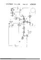
- FIG. 1 is a block diagram of a rotation rate measuring instrument without a facility for regulating the intensities of the component beams;
- FIGS. 2 and 3 show embodiments in which the instrument of FIG. 1 has been supplemented with a regulating facility
- FIG. 3a is a timing diagram illustrating the operation of the instrument of FIG. 1, and
- FIGS. 4 to 6 show further embodiments.
- FIG. 1 a rotation rate measuring instrument without a facility for eliminating systematic errors will be described with the aid of FIG. 1.
- This instrument is similar to that described in German patent application No. 31 36 688.
- a Bragg cell following the light source is used to advantage both to isolate the light source from light reflected back to it and to produce a pulsed light beam; in addition, it serves as a beam splitter.
- some of the modulating-signal generating and evaluating circuits were combined in a signal-processing circuit 100 for simplicity.
- a light beam produced by a laser 1 enters a Bragg cell 2.
- the Bragg cell 2 is used as an active beam splitter.
- a drive signal of frequency f B is applied to it periodically through a switch 15 controlled at the frequency f SL .
- the frequency f SL is equal to 1/2 ⁇ , where ⁇ is the time taken by a light beam to travel around the optical wave-guide mentioned in the following.
- ⁇ is the time taken by a light beam to travel around the optical wave-guide mentioned in the following.
- the laser light beam entering the Bragg cell 2 is deflected by a given angle and travels to a single-mode filter 3.
- the output beam of the single-mode filter 3 enters a passive beam splitter 4, which splits it into two component beams I CW and I CCW .
- the Bragg cell 5 to which the component beam I CW is directed, is driven alternately at the frequencies f MH and f ML .
- a switch 33 switches between these two frequencies at the frequency f S .
- the Bragg cell 6, to which the component beam I CCW is directed, is driven by the output signal of a voltage-controlled oscillator (VCO) 26.
- VCO voltage-controlled oscillator
- the component beams issuing from the Bragg cells 5 and 6 are coupled into a coiled optical waveguide 9. After emerging from the optical waveguide, the component beams I CCW and I CW enter the Bragg cells 5 and 6, respectively.
- the passive beam splitter recombines the two component beams, and the resulting beam passes through the single-mode filter 3 to the active beam splitter 2, which is implemented with a Bragg cell.
- the drive frequency f B is switched on and off at intervals of 2 ⁇ by means of the switch 15.
- no drive signal is applied to the beam splitter 2, i.e., the beam passes through the beam splitter 2 undeviated and, thus, travels not to the laser 1 but to a deviating mirror which directs it to an optical-to-electrical transducer 14.
- the output signal of the latter is fed to an input E1 of the signal-processing circuit 100.
- the signal-processing circuit further includes two oscillators 30 and 31, which generate signals with the frequencies f MH and f ML , respectively. These signals are applied to outputs A1 and A2, respectively, of the signal-processing circuit.
- the signals generated by the oscillators are also applied to a mixer 40, whose output is fed to a bandpass filter 41 followed by a divider stage 42.
- the output signal of the divider 42 is the second input signal for the mixer 43, which is fed with the output signal from the VCO 26, as mentioned above.
- the output of the mixer 43 is fed to an integrator 44, from whose output signal the rotation rate is determined in a device 45 in a manner known per se.
- the rotation rate is indicated by an indicator 46.
- the outputs of the oscillators 30 and 31 are fed to the above-mentioned switch 33. It should be mentioned that the control signals for the individual devices--provided that they have the same frequency--are derived from a single generator and, hence, are in synchronism.
- the output signals of the oscillators 30, 31 have different intensities; the output beam of the Bragg cell strikes the optical waveguide 9 at slightly different points depending on the respective drive frequency).
- a drive signal of frequency f B and no drive signal are alternately applied to the Bragg cell 2.
- the light beam issuing from the laser is directed to the single-mode filter or to an absorber (not shown), as mentioned previously.
- the light beam from which the two component beams are derived is a pulse beam.
- the sample-and-hold hold circuit 22 is, therefore, controlled at the same frequency at which the switch 15 is controlled, namely the frequency f SL .
- the controller controls the VCO 26 in such a way that the signal of frequency f S , at which the switch 33 is controlled, disappears.
- the other input signal for the mixer 43 is the output signal of the VCO 26.
- a difference frequency is obtained which is directly proportional to the rotation rate.
- beam-splitting mirrors 7 and 11 are provided between each of the Bragg cells 5, 6 and the two ends of the fiber. These beam-splitting mirrors are so disposed in the beam path that a portion of each of the component beams emerging from the optical waveguide strikes an additional optical-to-electrical transducer 13, 12.
- the output signals of these optical-to-electrical transducers are fed to a differential amplifier 54, which is followed by a controller 55.
- the latter controls a variable-gain amplifier 56, which is inserted in the line between the switch 33 and the Bragg cell 5, in such a way that the drive signals for the Bragg cell 5, having the frequencies f MH and f ML , have the same intensity.
- the beam-splitting mirrors are designed to transmit approximately 10% of the incident component beam to the associated optical-to-electrical transducer.
- the signals with the frequencies f MH and f ML are applied to the Bragg cell 5 through a switch 18, and the signal with the frequency f VCO is applied to the Bragg cell 6 through a switch 19. These switches are controlled with a signal of frequency f SB .
- beam-splitting mirrors 7 and 11 are provided between the Bragg cells 5, 6 and each end of the optical waveguide 9.
- the component beams transmitted by the mirrors do not travel to one optical-to-electrical transducer each (like in FIG. 2) but to a single optical-to-electrical transducer 17. It is therefore necessary to separate the component beam I CW and I CCW in time. To accomplish this, the switches 18 and 19 are switched so that during given times,
- both Bragg cells 5 and 6 are active.
- a Bragg cell is described as "active" if it is driven with such a signal that the component beam is coupled into that end of the optical waveguide associated with this cell.
- Two switches 18, 19 are driven with signals of frequency f SB , which differ in phase.
- T 2 Both Bragg cells are active. Both component beams travel around the optical waveguide and are then combined for evaluation purposes.
- T 3 Bragg cell 5 is inactive. After the time T 0 +T 1 +T 2 + ⁇ , I CCW is present at the input of the optical-to-electrical transducer 17.
- T 4 Like in T 2 .
- the output of the optical-to-electrical transducer 17 is fed to an amplifier 57, which is followed by a sample-and-hold circuit 59.
- the output signal of the sample-and-hold circuit 59 has a constant value if the two component beams in the optical waveguide have the same intensity. If that is not the case (as shown in FIG. 3a), the output signal has a DC voltage component from which a controller 55 derives a control signal for a variable-gain amplifier 56 between the switch 33 and the Bragg cell 5.
- the undeflected portion can be sent directly to an optical-to-electrical transducer (indicated by a broken line in FIG. 3; reference numeral 20). In this case, the two beam-splitting mirrors 7 and 11 are not necessary.
- the component beam I CW After travelling around the optical waveguide 9, the component beam I CW , shifted in frequency by f MH or f ML , is directed to the Bragg cell 6 via a beam-splitting mirror 11.
- the latter couples out a certain portion of the component beam which is directed to an optical-to-electrical transducer 12.
- another beam-splitting mirror 7 is disposed between the Bragg cell 5 and the other end of the optical waveguide.
- the Bragg cell may be driven so that not the entire component beam is deviated, but that a certain portion of this component beam passes through the Bragg cell unchanged in direction, and this undeviated component beam enters an optical-to-electrical transducer 16.
- This is indicated by a broken line in FIG. 4.
- the two beam splitting mirrors 11 and 7 are not necessary.
- the corresponding electric signal is fed to an amplifier 50 followed by a band-pass filter 51 whose midfrequency is equal to f S .
- the output of this band-pass filter is fed to a sample-and-hold circuit 52, which is controlled by a signal of frequency f S .
- a controller 53 derives a control signal.
- This control signal controls a variable-gain amplifier 32 between the output A1 and the switch 33 in such a way that the output signal of the optical-to-electrical transducer 12 contains no spectral component at the frequency f S .
- the Bragg cell 2 is driven with two different drive signals of frequency f B and zero frequency, respectively.
- the entire light beam produced by the laser is deflected in the direction of the single-mode filter, and, on the other hand, the entire beam coming back from the optical waveguide is directed to the optical-to-electrical transducer 14 via a deviating mirror.
- the Bragg cell 2 is preferably driven so as to pass the light beam resulting from the superposition of the two component beams to the transducer 14 only during the times that this light beam is present, so that a corresponding electric signal is applied to the signal-processing circuit 100 only during these times.
- the component beams travelling around the optical waveguide 9 are assumed to be pulsed component beams. Pulsed component beams are again obtained by driving the Bragg cell 2 in a suitable manner. As described in connection with other embodiments and FIG. 1, a switch 15 switches between the two drive signals, one of which has the frequency f B , at the frequency f SL .
- the output signal of the optical-to-electrical transducer 14 is applied not only to the input E1 of the signal-processing circuit 100 but also to an amplifier 60 followed by a sample-and-hold circuit 61, which is controlled at the frequency f SB .
- the output signal of the sample-and-hold circuit passes through a band-pass filter 62, whose midfrequency is f S , to an additional sample-and-hold circuit 63, which is controlled at the frequency f S .
- a controller 64 derives a control signal which controls a variable-gain amplifier 32 connected between the output A1 and the switch 33.
- An additional switch 19 between the output A3 and the Bragg cell 6 is controlled at the frequency f SB .
- no further optical-to-electrical transducers are required.
- the operation of the arrangement is as follows. To be able to measure intensity differences between the signals of frequency f MH and f ML , it must be possible to measure the intensity of the signal I CW , i.e., of the uncombined signal. To accomplish this, instead of applying the signal from the output A3 to the Bragg cell 6 continuously, switching is effected between this signal and zero frequency. At zero frequency, the Bragg cell 6 no longer couples the light beam entering it into the optical waveguide. Thus, during the time that the switch 19 is in this position, only the component beam I CW is present in the optical waveguide.
- the switch 19 After the time ⁇ (propagation time in the optical waveguide), the switch 19 must return to the position in which the signal of frequency f VCO is applied to the Bragg cell 6, so that a reciprocal construction is obtained again, i.e., that I CW can travel to the optical-to-electrical transducer.
- the control is performed so that light pulses entering the optical-to-electrical transducer are alternately the combined signal (I CW plus I CCW ) and only the component beam I CW .
- the signal-processing circuit 100 determines the rotation rate in the known manner, while the controller 64 derives the control signal for the variable-gain amplifier 32.
- control signals having the same frequency are synchronous with one another unless otherwise stated.
- controllers were not dealt with in detail, because those skilled in the art will readily be able to implement them if it is known what control action has to be taken and which signal contains which information to be used for control purposes.
Landscapes
- Engineering & Computer Science (AREA)
- Physics & Mathematics (AREA)
- Power Engineering (AREA)
- Optics & Photonics (AREA)
- Electromagnetism (AREA)
- General Physics & Mathematics (AREA)
- Radar, Positioning & Navigation (AREA)
- Remote Sensing (AREA)
- Lasers (AREA)
- Optical Modulation, Optical Deflection, Nonlinear Optics, Optical Demodulation, Optical Logic Elements (AREA)
- Optical Communication System (AREA)
Applications Claiming Priority (2)
| Application Number | Priority Date | Filing Date | Title |
|---|---|---|---|
| DE3247014 | 1982-12-18 | ||
| DE19823247014 DE3247014A1 (de) | 1982-12-18 | 1982-12-18 | Einrichtung zur messung der rotationsgeschwindigkeit |
Publications (1)
| Publication Number | Publication Date |
|---|---|
| US4569593A true US4569593A (en) | 1986-02-11 |
Family
ID=6181114
Family Applications (1)
| Application Number | Title | Priority Date | Filing Date |
|---|---|---|---|
| US06/562,142 Expired - Lifetime US4569593A (en) | 1982-12-18 | 1983-12-16 | Rotation rate measuring instrument |
Country Status (4)
| Country | Link |
|---|---|
| US (1) | US4569593A (de) |
| EP (1) | EP0113889B1 (de) |
| AU (1) | AU569268B2 (de) |
| DE (2) | DE3247014A1 (de) |
Cited By (6)
| Publication number | Priority date | Publication date | Assignee | Title |
|---|---|---|---|---|
| US4702600A (en) * | 1984-07-20 | 1987-10-27 | Litef Gmbh | Method and apparatus for measuring angular rate with a passive optical resonator |
| US4756620A (en) * | 1984-07-31 | 1988-07-12 | Teldix Gmbh | Signal evaluation method for a fiber-optic rotation sensor |
| US5018857A (en) * | 1988-09-15 | 1991-05-28 | Honeywell Inc. | Passive ring resonator gyro with polarization rotating ring path |
| US5157461A (en) * | 1990-06-14 | 1992-10-20 | Smiths Industries Aerospace & Defense Systems Inc. | Interface configuration for rate sensor apparatus |
| US5442442A (en) * | 1987-10-28 | 1995-08-15 | Litton Systems, Inc. | Ring laser gyroscope scale factor error control apparatus and method control apparatus and method |
| US5604309A (en) * | 1994-03-28 | 1997-02-18 | The Charles Stark Draper Laboratory, Inc. | Electronics for Coriolis force and other sensors |
Families Citing this family (4)
| Publication number | Priority date | Publication date | Assignee | Title |
|---|---|---|---|---|
| DE3426867A1 (de) * | 1984-07-20 | 1986-01-30 | LITEF Litton Technische Werke der Hellige GmbH, 7800 Freiburg | Verfahren und einrichtung zur drehratenmessung unter verwendung des sagnac-effekts |
| DE3446663A1 (de) * | 1984-12-21 | 1986-07-10 | Standard Elektrik Lorenz Ag, 7000 Stuttgart | Einrichtung zur messung der drehgeschwindigkeit |
| US4842358A (en) * | 1987-02-20 | 1989-06-27 | Litton Systems, Inc. | Apparatus and method for optical signal source stabilization |
| US5627644A (en) * | 1995-06-07 | 1997-05-06 | Sanders; Glen A. | Kerr effect compensation by optical power balancing in interferometric fiber optic gyroscopes |
Citations (1)
| Publication number | Priority date | Publication date | Assignee | Title |
|---|---|---|---|---|
| US4373814A (en) * | 1979-05-02 | 1983-02-15 | Thomson-Csf | Compact optical coupling device and optical-fiber interferometer gyrometer comprising such a device |
Family Cites Families (6)
| Publication number | Priority date | Publication date | Assignee | Title |
|---|---|---|---|---|
| US4372685A (en) * | 1979-01-15 | 1983-02-08 | Max-Planck-Gesellschaft Zur Forderung Der Wissenschaften E.V. | Method and arrangement for the measurement of rotations |
| FR2449897A1 (fr) * | 1979-02-23 | 1980-09-19 | Thomson Csf | Gyrometre interferometrique a fibre optique particulierement adapte a la mesure de faibles vitesses de rotation |
| DE2936269A1 (de) * | 1979-09-07 | 1981-03-19 | Siemens AG, 1000 Berlin und 8000 München | Ringinterferometer |
| FR2471583A1 (fr) * | 1979-12-14 | 1981-06-19 | Thomson Csf | Procede et dispositif de modulation de la phase des ondes circulant dans un interferometre en anneau |
| FR2475220A1 (fr) * | 1980-02-01 | 1981-08-07 | Electricite De France | Dispositif de detection d'ondes electromagnetiques, typiquement lumineuses, en quadrature de phase avec balance heterodyne. application aux velocimetres doppler et gyrometres sagnac |
| DE3136688C2 (de) * | 1981-09-16 | 1984-07-26 | Standard Elektrik Lorenz Ag, 7000 Stuttgart | Einrichtung zur Messung der Rotationsgeschwindigkeit |
-
1982
- 1982-12-18 DE DE19823247014 patent/DE3247014A1/de not_active Withdrawn
-
1983
- 1983-12-05 AU AU21958/83A patent/AU569268B2/en not_active Expired
- 1983-12-15 EP EP83112642A patent/EP0113889B1/de not_active Expired
- 1983-12-15 DE DE8383112642T patent/DE3376147D1/de not_active Expired
- 1983-12-16 US US06/562,142 patent/US4569593A/en not_active Expired - Lifetime
Patent Citations (1)
| Publication number | Priority date | Publication date | Assignee | Title |
|---|---|---|---|---|
| US4373814A (en) * | 1979-05-02 | 1983-02-15 | Thomson-Csf | Compact optical coupling device and optical-fiber interferometer gyrometer comprising such a device |
Non-Patent Citations (2)
| Title |
|---|
| "Sensitive Fiber-Optic Gyroscopes", Physics Today, 10-1981, vol. 34, No. 10. |
| Sensitive Fiber Optic Gyroscopes , Physics Today, 10 1981, vol. 34, No. 10. * |
Cited By (7)
| Publication number | Priority date | Publication date | Assignee | Title |
|---|---|---|---|---|
| US4702600A (en) * | 1984-07-20 | 1987-10-27 | Litef Gmbh | Method and apparatus for measuring angular rate with a passive optical resonator |
| US4756620A (en) * | 1984-07-31 | 1988-07-12 | Teldix Gmbh | Signal evaluation method for a fiber-optic rotation sensor |
| US5442442A (en) * | 1987-10-28 | 1995-08-15 | Litton Systems, Inc. | Ring laser gyroscope scale factor error control apparatus and method control apparatus and method |
| US5018857A (en) * | 1988-09-15 | 1991-05-28 | Honeywell Inc. | Passive ring resonator gyro with polarization rotating ring path |
| US5157461A (en) * | 1990-06-14 | 1992-10-20 | Smiths Industries Aerospace & Defense Systems Inc. | Interface configuration for rate sensor apparatus |
| US5604309A (en) * | 1994-03-28 | 1997-02-18 | The Charles Stark Draper Laboratory, Inc. | Electronics for Coriolis force and other sensors |
| US5672949A (en) * | 1994-03-28 | 1997-09-30 | The Charles Stark Draper Laboratory, Inc. | Electronics for Coriolis force and other sensors |
Also Published As
| Publication number | Publication date |
|---|---|
| AU2195883A (en) | 1984-06-21 |
| DE3247014A1 (de) | 1984-06-20 |
| DE3376147D1 (en) | 1988-05-05 |
| EP0113889B1 (de) | 1988-03-30 |
| EP0113889A2 (de) | 1984-07-25 |
| AU569268B2 (en) | 1988-01-28 |
| EP0113889A3 (en) | 1985-01-09 |
Similar Documents
| Publication | Publication Date | Title |
|---|---|---|
| US4265541A (en) | Interferometric laser gyrometer | |
| EP0401799B1 (de) | Längenmessgerät | |
| US4834538A (en) | Fibre optic gyroscope with nulling feedback control loop | |
| US5054912A (en) | Optical distance-measuring device | |
| US4569593A (en) | Rotation rate measuring instrument | |
| US4573795A (en) | Rotation rate measuring instrument | |
| JPH071808B2 (ja) | 角速度センサ | |
| JPS6371674A (ja) | レ−ザ−測距装置 | |
| US4591269A (en) | Rotation rate measuring instrument | |
| US5459571A (en) | Multiple control frequency phase modulator in phase modulated interferometer precision distance measuring system | |
| WO1992004597A1 (en) | Optical interference angular velocity meter | |
| US5818589A (en) | Device for and method of measuring absolute rotations in several directions in space | |
| US4628473A (en) | System for autocorrelating optical radiation signals | |
| EP1547211A1 (de) | Frequenzstabilisierter laser mit phasenmoduliertem rückgestreutem licht | |
| EP0297556B1 (de) | Messvorrichtung für die spektrale Emissionsbreite einer Lichtquelle | |
| JPS6061614A (ja) | 光共振器の固有共振周波数の相違を測定する装置 | |
| JPH06112572A (ja) | 光共振器および光周波数掃引光源 | |
| JPH06323810A (ja) | マルチプローブ変位測定装置 | |
| EP0412468B1 (de) | Synthetische Sägezahnsteuerung für Faserkreisel | |
| JP2756967B2 (ja) | スペクトル分析器 | |
| RU2029251C1 (ru) | Устройство для измерения амплитуд малых периодических линейных перемещений | |
| JPH0550711B2 (de) | ||
| SU1383089A2 (ru) | Устройство дл измерени фазовых сдвигов лазерного излучени | |
| JPH06235641A (ja) | 光ファイバジャイロスコープ | |
| SU340211A1 (ru) | АГА АКТИЕБОЛАГ»(Швеци ) |
Legal Events
| Date | Code | Title | Description |
|---|---|---|---|
| AS | Assignment |
Owner name: INTERNATIONAL STANDARD ELECTRIC CORPORATION 320 PA Free format text: ASSIGNMENT OF ASSIGNORS INTEREST.;ASSIGNORS:AUCH, WILFRIED;SCHLEMPER, EBERHARD;REEL/FRAME:004210/0546 Effective date: 19831117 |
|
| STCF | Information on status: patent grant |
Free format text: PATENTED CASE |
|
| AS | Assignment |
Owner name: ALCATEL N.V., DE LAIRESSESTRAAT 153, 1075 HK AMSTE Free format text: ASSIGNMENT OF ASSIGNORS INTEREST.;ASSIGNOR:INTERNATIONAL STANDARD ELECTRIC CORPORATION, A CORP OF DE;REEL/FRAME:004718/0023 Effective date: 19870311 |
|
| FPAY | Fee payment |
Year of fee payment: 4 |
|
| FEPP | Fee payment procedure |
Free format text: PAYOR NUMBER ASSIGNED (ORIGINAL EVENT CODE: ASPN); ENTITY STATUS OF PATENT OWNER: LARGE ENTITY |
|
| FPAY | Fee payment |
Year of fee payment: 8 |
|
| FEPP | Fee payment procedure |
Free format text: PAYOR NUMBER ASSIGNED (ORIGINAL EVENT CODE: ASPN); ENTITY STATUS OF PATENT OWNER: LARGE ENTITY Free format text: PAYER NUMBER DE-ASSIGNED (ORIGINAL EVENT CODE: RMPN); ENTITY STATUS OF PATENT OWNER: LARGE ENTITY |
|
| FPAY | Fee payment |
Year of fee payment: 12 |