US4570099A - Thermionic electron emitters - Google Patents
Thermionic electron emitters Download PDFInfo
- Publication number
- US4570099A US4570099A US06/660,248 US66024884A US4570099A US 4570099 A US4570099 A US 4570099A US 66024884 A US66024884 A US 66024884A US 4570099 A US4570099 A US 4570099A
- Authority
- US
- United States
- Prior art keywords
- metal
- osmium
- fully alloyed
- tungsten
- matrix
- Prior art date
- Legal status (The legal status is an assumption and is not a legal conclusion. Google has not performed a legal analysis and makes no representation as to the accuracy of the status listed.)
- Expired - Fee Related
Links
- 229910052762 osmium Inorganic materials 0.000 claims abstract description 83
- SYQBFIAQOQZEGI-UHFFFAOYSA-N osmium atom Chemical compound [Os] SYQBFIAQOQZEGI-UHFFFAOYSA-N 0.000 claims abstract description 82
- WFKWXMTUELFFGS-UHFFFAOYSA-N tungsten Chemical compound [W] WFKWXMTUELFFGS-UHFFFAOYSA-N 0.000 claims abstract description 57
- 229910052721 tungsten Inorganic materials 0.000 claims abstract description 57
- 239000010937 tungsten Substances 0.000 claims abstract description 56
- 239000011159 matrix material Substances 0.000 claims abstract description 55
- 239000011248 coating agent Substances 0.000 claims abstract description 35
- 238000000576 coating method Methods 0.000 claims abstract description 35
- 239000000203 mixture Substances 0.000 claims abstract description 22
- 238000000034 method Methods 0.000 claims abstract description 17
- 239000012190 activator Substances 0.000 claims abstract description 16
- 239000002184 metal Substances 0.000 claims description 89
- 229910052751 metal Inorganic materials 0.000 claims description 88
- QVQLCTNNEUAWMS-UHFFFAOYSA-N barium oxide Chemical compound [Ba]=O QVQLCTNNEUAWMS-UHFFFAOYSA-N 0.000 claims description 29
- 229910045601 alloy Inorganic materials 0.000 claims description 26
- 239000000956 alloy Substances 0.000 claims description 26
- PNEYBMLMFCGWSK-UHFFFAOYSA-N Alumina Chemical compound [O-2].[O-2].[O-2].[Al+3].[Al+3] PNEYBMLMFCGWSK-UHFFFAOYSA-N 0.000 claims description 24
- GKOZUEZYRPOHIO-UHFFFAOYSA-N iridium atom Chemical compound [Ir] GKOZUEZYRPOHIO-UHFFFAOYSA-N 0.000 claims description 20
- 229910052741 iridium Inorganic materials 0.000 claims description 19
- 239000010410 layer Substances 0.000 claims description 18
- 239000000463 material Substances 0.000 claims description 17
- KJTLSVCANCCWHF-UHFFFAOYSA-N Ruthenium Chemical compound [Ru] KJTLSVCANCCWHF-UHFFFAOYSA-N 0.000 claims description 14
- 229910052788 barium Inorganic materials 0.000 claims description 14
- DSAJWYNOEDNPEQ-UHFFFAOYSA-N barium atom Chemical compound [Ba] DSAJWYNOEDNPEQ-UHFFFAOYSA-N 0.000 claims description 14
- 150000001875 compounds Chemical class 0.000 claims description 14
- 150000002739 metals Chemical class 0.000 claims description 14
- 229910052707 ruthenium Inorganic materials 0.000 claims description 14
- 229910052702 rhenium Inorganic materials 0.000 claims description 13
- WUAPFZMCVAUBPE-UHFFFAOYSA-N rhenium atom Chemical compound [Re] WUAPFZMCVAUBPE-UHFFFAOYSA-N 0.000 claims description 13
- ZOKXTWBITQBERF-UHFFFAOYSA-N Molybdenum Chemical compound [Mo] ZOKXTWBITQBERF-UHFFFAOYSA-N 0.000 claims description 12
- 239000011733 molybdenum Substances 0.000 claims description 12
- 238000004519 manufacturing process Methods 0.000 claims description 11
- 229910052750 molybdenum Inorganic materials 0.000 claims description 11
- 229910052703 rhodium Inorganic materials 0.000 claims description 11
- 239000010948 rhodium Substances 0.000 claims description 11
- MHOVAHRLVXNVSD-UHFFFAOYSA-N rhodium atom Chemical compound [Rh] MHOVAHRLVXNVSD-UHFFFAOYSA-N 0.000 claims description 11
- 238000010438 heat treatment Methods 0.000 claims description 8
- FYYHWMGAXLPEAU-UHFFFAOYSA-N Magnesium Chemical compound [Mg] FYYHWMGAXLPEAU-UHFFFAOYSA-N 0.000 claims description 6
- 229910052784 alkaline earth metal Inorganic materials 0.000 claims description 6
- 150000001342 alkaline earth metals Chemical class 0.000 claims description 6
- 239000011777 magnesium Substances 0.000 claims description 6
- 229910052749 magnesium Inorganic materials 0.000 claims description 6
- 239000000843 powder Substances 0.000 claims description 6
- 238000004544 sputter deposition Methods 0.000 claims description 5
- 229910052712 strontium Inorganic materials 0.000 claims description 5
- CIOAGBVUUVVLOB-UHFFFAOYSA-N strontium atom Chemical compound [Sr] CIOAGBVUUVVLOB-UHFFFAOYSA-N 0.000 claims description 5
- 238000005275 alloying Methods 0.000 claims description 4
- 229910052810 boron oxide Inorganic materials 0.000 claims description 4
- JKWMSGQKBLHBQQ-UHFFFAOYSA-N diboron trioxide Chemical compound O=BOB=O JKWMSGQKBLHBQQ-UHFFFAOYSA-N 0.000 claims description 4
- 239000002245 particle Substances 0.000 claims description 4
- 238000003825 pressing Methods 0.000 claims description 4
- 238000005245 sintering Methods 0.000 claims description 4
- 239000002344 surface layer Substances 0.000 claims description 4
- OYPRJOBELJOOCE-UHFFFAOYSA-N Calcium Chemical compound [Ca] OYPRJOBELJOOCE-UHFFFAOYSA-N 0.000 claims description 3
- 229910052791 calcium Inorganic materials 0.000 claims description 3
- 239000011575 calcium Substances 0.000 claims description 3
- 238000005470 impregnation Methods 0.000 claims description 2
- 238000001704 evaporation Methods 0.000 claims 1
- 238000009792 diffusion process Methods 0.000 abstract description 9
- 238000012986 modification Methods 0.000 abstract description 3
- 230000004048 modification Effects 0.000 abstract description 3
- 230000004888 barrier function Effects 0.000 abstract description 2
- UFHFLCQGNIYNRP-UHFFFAOYSA-N Hydrogen Chemical compound [H][H] UFHFLCQGNIYNRP-UHFFFAOYSA-N 0.000 description 5
- BRPQOXSCLDDYGP-UHFFFAOYSA-N calcium oxide Chemical compound [O-2].[Ca+2] BRPQOXSCLDDYGP-UHFFFAOYSA-N 0.000 description 5
- ODINCKMPIJJUCX-UHFFFAOYSA-N calcium oxide Inorganic materials [Ca]=O ODINCKMPIJJUCX-UHFFFAOYSA-N 0.000 description 5
- 239000000292 calcium oxide Substances 0.000 description 5
- 238000011161 development Methods 0.000 description 5
- 230000018109 developmental process Effects 0.000 description 5
- 229910052739 hydrogen Inorganic materials 0.000 description 5
- 239000001257 hydrogen Substances 0.000 description 5
- 150000004645 aluminates Chemical class 0.000 description 4
- 238000006243 chemical reaction Methods 0.000 description 4
- 230000032683 aging Effects 0.000 description 3
- 230000015572 biosynthetic process Effects 0.000 description 3
- 230000000694 effects Effects 0.000 description 3
- 239000000945 filler Substances 0.000 description 3
- MHAJPDPJQMAIIY-UHFFFAOYSA-N hydrogen peroxide Substances OO MHAJPDPJQMAIIY-UHFFFAOYSA-N 0.000 description 2
- MGRWKWACZDFZJT-UHFFFAOYSA-N molybdenum tungsten Chemical compound [Mo].[W] MGRWKWACZDFZJT-UHFFFAOYSA-N 0.000 description 2
- 239000002243 precursor Substances 0.000 description 2
- 238000012545 processing Methods 0.000 description 2
- 239000003870 refractory metal Substances 0.000 description 2
- 239000004065 semiconductor Substances 0.000 description 2
- NLXLAEXVIDQMFP-UHFFFAOYSA-N Ammonium chloride Substances [NH4+].[Cl-] NLXLAEXVIDQMFP-UHFFFAOYSA-N 0.000 description 1
- VHUUQVKOLVNVRT-UHFFFAOYSA-N Ammonium hydroxide Chemical compound [NH4+].[OH-] VHUUQVKOLVNVRT-UHFFFAOYSA-N 0.000 description 1
- 229910000906 Bronze Inorganic materials 0.000 description 1
- BVKZGUZCCUSVTD-UHFFFAOYSA-L Carbonate Chemical compound [O-]C([O-])=O BVKZGUZCCUSVTD-UHFFFAOYSA-L 0.000 description 1
- 229910000575 Ir alloy Inorganic materials 0.000 description 1
- 229910001182 Mo alloy Inorganic materials 0.000 description 1
- 229910000820 Os alloy Inorganic materials 0.000 description 1
- 229910000929 Ru alloy Inorganic materials 0.000 description 1
- 101100386054 Saccharomyces cerevisiae (strain ATCC 204508 / S288c) CYS3 gene Proteins 0.000 description 1
- 229910001080 W alloy Inorganic materials 0.000 description 1
- FQNGWRSKYZLJDK-UHFFFAOYSA-N [Ca].[Ba] Chemical compound [Ca].[Ba] FQNGWRSKYZLJDK-UHFFFAOYSA-N 0.000 description 1
- WOIHABYNKOEWFG-UHFFFAOYSA-N [Sr].[Ba] Chemical compound [Sr].[Ba] WOIHABYNKOEWFG-UHFFFAOYSA-N 0.000 description 1
- 239000011149 active material Substances 0.000 description 1
- 150000001341 alkaline earth metal compounds Chemical class 0.000 description 1
- 235000011114 ammonium hydroxide Nutrition 0.000 description 1
- 238000000137 annealing Methods 0.000 description 1
- 239000007864 aqueous solution Substances 0.000 description 1
- -1 at 20 Chemical compound 0.000 description 1
- AYJRCSIUFZENHW-DEQYMQKBSA-L barium(2+);oxomethanediolate Chemical compound [Ba+2].[O-][14C]([O-])=O AYJRCSIUFZENHW-DEQYMQKBSA-L 0.000 description 1
- 239000010974 bronze Substances 0.000 description 1
- 150000004649 carbonic acid derivatives Chemical class 0.000 description 1
- KUNSUQLRTQLHQQ-UHFFFAOYSA-N copper tin Chemical compound [Cu].[Sn] KUNSUQLRTQLHQQ-UHFFFAOYSA-N 0.000 description 1
- 239000013078 crystal Substances 0.000 description 1
- 239000008367 deionised water Substances 0.000 description 1
- 230000001419 dependent effect Effects 0.000 description 1
- 238000013461 design Methods 0.000 description 1
- 238000010586 diagram Methods 0.000 description 1
- 239000002019 doping agent Substances 0.000 description 1
- 238000010894 electron beam technology Methods 0.000 description 1
- 238000002474 experimental method Methods 0.000 description 1
- 238000010304 firing Methods 0.000 description 1
- 239000011229 interlayer Substances 0.000 description 1
- 229910044991 metal oxide Inorganic materials 0.000 description 1
- GIDFDWJDIHKDMB-UHFFFAOYSA-N osmium ruthenium Chemical compound [Ru].[Os] GIDFDWJDIHKDMB-UHFFFAOYSA-N 0.000 description 1
- 229910000489 osmium tetroxide Inorganic materials 0.000 description 1
- 230000003647 oxidation Effects 0.000 description 1
- 238000007254 oxidation reaction Methods 0.000 description 1
- 239000004033 plastic Substances 0.000 description 1
- 229920003023 plastic Polymers 0.000 description 1
- 239000012255 powdered metal Substances 0.000 description 1
- 230000008569 process Effects 0.000 description 1
- 239000000700 radioactive tracer Substances 0.000 description 1
- 230000009467 reduction Effects 0.000 description 1
- 230000006641 stabilisation Effects 0.000 description 1
- 101150035983 str1 gene Proteins 0.000 description 1
- 239000000126 substance Substances 0.000 description 1
- 231100000331 toxic Toxicity 0.000 description 1
- 230000002588 toxic effect Effects 0.000 description 1
- 229910052723 transition metal Inorganic materials 0.000 description 1
- 150000003624 transition metals Chemical class 0.000 description 1
- 238000005406 washing Methods 0.000 description 1
Images


Classifications
-
- H—ELECTRICITY
- H01—ELECTRIC ELEMENTS
- H01J—ELECTRIC DISCHARGE TUBES OR DISCHARGE LAMPS
- H01J1/00—Details of electrodes, of magnetic control means, of screens, or of the mounting or spacing thereof, common to two or more basic types of discharge tubes or lamps
- H01J1/02—Main electrodes
- H01J1/13—Solid thermionic cathodes
- H01J1/14—Solid thermionic cathodes characterised by the material
-
- H—ELECTRICITY
- H01—ELECTRIC ELEMENTS
- H01J—ELECTRIC DISCHARGE TUBES OR DISCHARGE LAMPS
- H01J9/00—Apparatus or processes specially adapted for the manufacture, installation, removal, maintenance of electric discharge tubes, discharge lamps, or parts thereof; Recovery of material from discharge tubes or lamps
- H01J9/02—Manufacture of electrodes or electrode systems
- H01J9/04—Manufacture of electrodes or electrode systems of thermionic cathodes
- H01J9/042—Manufacture, activation of the emissive part
- H01J9/047—Cathodes having impregnated bodies
Definitions
- the present invention relates to thermionic electron emitters.
- a thermionic cathode now known as "M"-type, is disclosed in U.S. Pat. No. 3,373,307.
- This cathode is a dispenser cathode which comprises a refractory metal matrix of tungsten (W) or tungsten-molybdenum in reactive relationship with an alkaline earth metal compound which supplies free barium or barium oxide to the emitting surface of the matrix.
- a thin porous coating of a refractory metal having a work function higher than that of tungsten covers the emitting surface. The coating may be sputtered on.
- the coating metal is selected from the group of osmium, iridium, ruthenium, and rhenium.
- the resultant cathode exhibits increased electron emission at the same temperature, or the same electron emission at a lower temperature, than that of a comparable cathode without the layer.
- osmium (Os) is preferred as the coating metal.
- the coating is a thin porous layer of an alloy of osmium and iridium or osmium and ruthenium to provide longer cathode lifetime and, less danger during manufacture, (osmium being readily oxidisable to an extremely toxic oxide). This coating is sputtered on.
- British Pat. No. 1,425,582 discloses a method of making an M-type cathode having a porous metal body in which the dangers of osmium are reduced.
- the method comprises the steps of forming a reducible impregnation mixture of at least one alkaline earth compound and a compound of another metal (e.g. osmium) having a higher work function than the porous metal of the body, and impregnating the porous metal body (e.g. tungsten) using the mixture and a reducing atmosphere whereby said another metal is released from its compound.
- the mixture is placed on the structure and heated in the reducing atmosphere.
- the osmium is released in a finely divided state.
- British Pat. No. 1,143,865 discloses a dispenser cathode called an MK cathode which is made by a method wherein a tungsten plate is first etched in an aqueous hydrogen peroxide/ammonia solution and rinsed with deionised water, the emissive surface of said plate is thereafter treated with an approximately 2% aqueous solution of OsO 4 and the grey to deep black deposit forming after a few minutes is, after thorough washing, reduced and sintered on to said plate by heating at 1200° C. for about 15 minutes in an atmosphere of hydrogen. This results in the tungsten plate being coated with Osmium.
- German Offenlegungsschrift No. 27 27187 discloses a type of thermionic cathode different to "M"-type, and referred to hereinafter as "mixed matrix" type.
- a preferred example of this cathode comprises particles of pure iridium mixed in fixed proportions with particles of pure tungsten. The particles are sintered together to form a continuous porous matrix. The matrix is filled with an active material in the form of an alkaline earth aluminate. The iridium and tungsten form an alloy, but for optimal results the alloy formation must be incomplete.
- the emission of such a cathode is greater than that of an ⁇ M ⁇ -type cathode,
- the optimum proportions of iridium and tungsten are 20% iridium and 80% tungsten.
- the iridium and tungsten mixture may be replaced by pure iridium, osmium, ruthenium, or rhenium or mixtures thereof or by a mixture of tungsten and one of those metals.
- a thermionic electron emitter including: material comprising about 15 to 45% of a first metal selected from the group consisting of osmium, iridium, ruthenium, rhodium, rhenium and alloys thereof, fully alloyed with 85 to 55% of a second metal selected from the group consisting of tungsten, molybdenum and alloys thereof; and an alkaline earth activator.
- a method of making a thermionic electron emitter comprising fully alloying 15 to 45% of a first metal selected from the group consisting of osmium, iridium, ruthenium, rhodium, rhenium and alloys thereof, with 85 to 55% of a second metal selected from the group consisting of tungsten molybdenum and alloys thereof, and incorporating the fully alloyed metals in the emitter with an alkaline earth activator.
- the emitter comprises about 20 to 30% of the first metal and about 80 to 70% of the second metal.
- the emitter comprises about 40% of the first metal and about 60% of the second metal.
- the preferred amounts may be departed from in practice deliberately to achieve enhanced life.
- the first metal comprises osmium and the second metal tungsten.
- the activator comprises a mixture of barium oxide or carbonate, an oxide or carbonate of an alkaline earth metal other than barium, and at least one of aluminium oxide and boron oxide.
- the metal other than barium may be strontium or magnesium or mixtures of barium strontium and magnesium.
- FIG. 1 is a section through a preferred thermionic cathode in accordance with the invention
- FIG. 2 shows a detail of a modification of the preferred cathode in accordance with the invention
- FIG. 3 shows part of another cathode in accordance with the invention
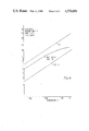
- FIG. 4 is a graph of zero field emission density versus temperature comparing a cathode in accordance with the invention with other types of cathode, and
- FIG. 5 is a schematic diagram of a method of manufacturing a further cathode in accordance with the invention.
- the cathode comprises a molybdenum tube 1 containing in a lower cavity a heater 2, and in an upper cavity a thermionic emitter 3.
- the emitter 3 comprises: a porous matrix 4 of tungsten impregnated with an activator in the form of a mixture of barium oxide, aluminium oxide, and calcium oxide in the molecular proportions 3:1:1/2 respectively; and a coating 5 on the free surface of the matrix.
- the coating 5 comprises a fully alloyed combination of osmium and tungsten having the proportions of about 20 to 30% osmium and 80 to 70% tungsten.
- the coating in this example is formed by co-sputtering osmium and tungsten in the desired proportions onto the impregnated matrix.
- the coating is 4000 ⁇ thick in this example, but it may have a thickness in the range 2000 to 15000 ⁇ .
- the osmium concentration will be lowered by diffusion into the matrix 4.
- the effect of this may be reduced by initially forming the coating with a greater proportion of osmium than quoted above.
- a thin interlayer 6 of pure osmium could be placed between the coating 5 and the matrix 4.
- the impregnant is doped with one precent or less of osmium to counteract the diffusion of osmium into the matrix. This is achieved by using the method of forming an impregnated ⁇ M ⁇ -type cathode disclosed in British Pat. No. 1,425,582 using 1% or less of osmium. Once the impregnated matrix is formed, the fully alloyed osmium/tungsten coating is formed on it.
- the coating may be formed by coevaporating the metals osmium and tungsten onto the matrix 4. This is done by directing an electron beam onto targets of osmium and tungsten to cause the metals to evaporate from the targets onto the matrix.
- the coating could also be formed by co-precipitating the metals onto the matrix from reducible compounds thereof.
- the whole emitter 3 comprises a fully alloyed mixture of osmium and tungsten in the approximate proportions 20 to 30% osmium and 80 to 70% tungsten, impregnated with an alkaline earth aluminate.
- the emitter of FIG. 3 is made for example by:
- furnacing at a temperature and for a time to enable full osmium/tungsten interdiffusion to occur during furnacing, (e.g. at a temperature in the range 1800° to 2000° C. for 5 to 10 hrs).
- An alternative method of making the emitter of FIG. 3 comprises
- osmium there may be used iridium, ruthenium, rhodium or rhenium. Furthermore alloys of any two or more of osmium, iridium, ruthenium, rhodium and rhenium may be used. Instead of tungsten, there may be used molybdenum or an alloy of tungsten and molybdenum. The proportions of the replacements of osmium and tungsten would be the same as those for osmium and tungsten as described hereinbefore.
- the impregnant may have the form described hereinbefore but in other proportions such as 4:1:1 or 5:2:3.
- another oxide of an alkaline earth metal other than barium may be used, and instead of aluminium oxide there may be used boron oxide.
- the metal other than barium may be strontium or magnesium or a mixture of any two or more of calcium, strontium and magnesium.
- oxides of the alkaline earth metal other than barium compounds which decompose on heating to oxides e.g. carbonates of those metals may be used.
- FIG. 2 There has been described with reference to FIG. 2 the provision of a layer 6 of osmium between the coating 5 and the matrix 4.
- the layer 6 acts as a diffusion barrier to reduce the diffusion of osmium from the coating 5 into the matrix.
- Another alternative is to dope the impregnant with osmium as described above.
- FIG. 5 describes the manufacture of a further cathode in which yet another manner of reducing diffusion is provided.
- a porous matrix of tungsten is impregnated with filler e.g. a plastics material to enable it to be machined (50) and then the filler is at least partially removed by firing in air (51).
- filler e.g. a plastics material to enable it to be machined (50) and then the filler is at least partially removed by firing in air (51).
- the button is then subjected to wet hydrogen at a temperature of 1000° to remove (by oxidation) remnants of the filler followed by dry hydrogen at 1800° C. to produce reducing conditions (52).
- Osmium is then sputtered onto the matrix to form a coating 4000 ⁇ thick (53).
- the button is then heated in a hydrogen atmosphere at 1800° C. for, for example, one hour to allow the osmium coating to diffuse into the matrix (54).
- activator e.g.
- barium calcium aluminate 55
- cleaned ultrasonically (56) fired in a hydrogen atmosphere at a temperature of e.g. 1000° C. for e.g. 2 to 5 minutes (57).
- a layer of osmium, corresponding to the layer 6 of FIG. 2 is then sputtered on (58) followed by the co-sputtering of Osmium and tungsten to form a fully alloyed layer of about 15 to 45% osmium and 85 to 55% tungsten, corresponding to layer 5 of FIG. 2(59).
- Steps 50 to 52 and 55 to 59 form the processing steps of a cathode as shown in FIG. 2.
- the extra steps 53 and 54 in which a further layer of osmium is provided and diffused into the matrix provide additional stabilisation of the surface layers, especially against surface diffusion.
- the inventor of the present invention believes that the cathodes in accordance with the present invention operate in the manner described hereinafter although this is not proven.
- the explanation is given in terms of osmium, barium and tungsten.
- Cathodes operate at about 1000° C. and at such temperatures osmium is not (as had previously been assumed by workers in the art) chemically inert but reacts with barium oxide to form a barium osmate compound.
- the transition metal d-orbitals are populated, for example Os VI being a d 2 system.
- These components have partially filled d-levels and are a natural "oxide bronze" analogous to the well known tungsten bronzes.
- the chemically combined osmium may be regarded as acting as a semiconductor "dopant"; its populated d-orbitals acting as the donor levels which give rise to n-type semiconduction. (In fact the concentration of osmium in cathodes is enormously higher than that used in conventional semiconductor doping).
- the osmium When chemically combined in a crystal lattice with barium oxide, the osmium affects the electronic structure which determines conductivity and work function.
- the continuous film of osmium is too readily available to react with the BaO emissive layer and chemically saturates it. This is non-optimum as excess BaO is necessary to form the particular osmate component with the best electronic structure for lowest work function.
- the relative rates of supply of osmium metal and barium oxide must be in the correct ratio.
- the desired osmium concentration in the emissive layer is less than saturation, and so the reaction rate of osmium with BaO must be controlled over the entire cathode surface.
- This control is achieved in accordance with the invention by fully alloying the osmium with the tungsten. This reduces the chemical potential of the osmium. Since the rate of reaction of osmium with barium oxide and the rate of barium oxide dispensation to the surface are both temperature dependent, the exact alloy composition, which gives rise to optimum doping of the emissive film varies with the operating temperature of the cathode which in turn depends on design operating current density.
- alloy compositions which provide optimum doping at appropriate temperatures lie in the range of approximately 20 to 40% osmium in tungsten.
- osmium doping is controlled to maximise emission.
- a cathode may thus be called a controlled doping (CD) cathode.
- FIG. 4 compares the performance of an example of a controlled doping cathode with an ⁇ M ⁇ -type cathode, and with a mixed-matrix type cathode.
- the mixed-matrix cathode comprised a matrix of osmium and tungsten which was aged for 500 hrs to maximise its emission before the comparison was made. Its emission density is greater than that of an osmium coated ⁇ M ⁇ -type cathode.
- the CD cathode (which was as described with reference to FIG. 1) gives an even greater emission density and without the need for a substantial ageing process, full emission being given almost immediately. Instead of operating the CD cathode to produce enhanced emission as compared with the M-type or mixed matrise-type cathode at the same temperature, it could be operated to give the same emission but at a lower temperature with a much longer life-time.
Landscapes
- Engineering & Computer Science (AREA)
- Manufacturing & Machinery (AREA)
- Solid Thermionic Cathode (AREA)
Applications Claiming Priority (2)
| Application Number | Priority Date | Filing Date | Title |
|---|---|---|---|
| GB7918610 | 1979-05-29 | ||
| GB7918610A GB2050045A (en) | 1979-05-29 | 1979-05-29 | Thermionic cathode |
Related Parent Applications (1)
| Application Number | Title | Priority Date | Filing Date |
|---|---|---|---|
| US06123575 Continuation | 1980-02-22 |
Publications (1)
| Publication Number | Publication Date |
|---|---|
| US4570099A true US4570099A (en) | 1986-02-11 |
Family
ID=10505498
Family Applications (1)
| Application Number | Title | Priority Date | Filing Date |
|---|---|---|---|
| US06/660,248 Expired - Fee Related US4570099A (en) | 1979-05-29 | 1984-10-12 | Thermionic electron emitters |
Country Status (3)
| Country | Link |
|---|---|
| US (1) | US4570099A (fr) |
| EP (1) | EP0019992A1 (fr) |
| GB (1) | GB2050045A (fr) |
Cited By (11)
| Publication number | Priority date | Publication date | Assignee | Title |
|---|---|---|---|---|
| US4735591A (en) * | 1987-04-15 | 1988-04-05 | The United States Of America As Represented By The Secretary Of The Army | Method of making a long life high current density cathode from tungsten and iridium powders using a barium iridiate as the impregnant |
| US4737679A (en) * | 1985-02-08 | 1988-04-12 | Hitachi, Ltd. | Impregnated cathode |
| US4820954A (en) * | 1986-12-19 | 1989-04-11 | Kabushiki Kaisha Toshiba | Indirectly heated cathode structure for electron tubes |
| US4823044A (en) * | 1988-02-10 | 1989-04-18 | Ceradyne, Inc. | Dispenser cathode and method of manufacture therefor |
| US5266414A (en) * | 1988-03-18 | 1993-11-30 | Varian Associates, Inc. | Solid solution matrix cathode |
| US5318468A (en) * | 1991-05-07 | 1994-06-07 | Licentia Patent-Verwaltungs-Gmbh | Dispenser cathode and process for preparing it |
| US5418070A (en) * | 1988-04-28 | 1995-05-23 | Varian Associates, Inc. | Tri-layer impregnated cathode |
| US5507675A (en) * | 1993-06-22 | 1996-04-16 | Thorn Microwave Devices Limited | Method of manufacturing a thermionic cathode structure |
| US5747921A (en) * | 1993-10-05 | 1998-05-05 | Goldstar Co., Ltd. | Impregnation type cathode for a cathodic ray tube |
| US6348756B1 (en) * | 1995-07-31 | 2002-02-19 | U.S. Philips Corporation | Electric discharge tube or discharge lamp and scandate dispenser cathode |
| RU2241279C2 (ru) * | 2002-05-15 | 2004-11-27 | Отдел электроэнергетических проблем РАН | Устройство для получения электрической энергии |
Families Citing this family (10)
| Publication number | Priority date | Publication date | Assignee | Title |
|---|---|---|---|---|
| FR2469792A1 (fr) * | 1979-11-09 | 1981-05-22 | Thomson Csf | Cathode thermo-ionique, son procede de fabrication et tube electronique incorporant une telle cathode |
| DE3122950A1 (de) * | 1981-06-10 | 1983-01-05 | Licentia Patent-Verwaltungs-Gmbh, 6000 Frankfurt | Verfahren zum herstellen einer vorratskathode |
| DE3561180D1 (en) * | 1984-02-24 | 1988-01-21 | Emi Varian Ltd | Thermionic electron emitter |
| GB2188771B (en) * | 1986-04-01 | 1990-12-19 | Ceradyne Inc | Dispenser cathode and method of manufacture therefor |
| GB2196786A (en) * | 1986-10-27 | 1988-05-05 | Ceradyne Inc | Cathode assembly |
| US5041041A (en) * | 1986-12-22 | 1991-08-20 | Gte Products Corporation | Method of fabricating a composite lamp filament |
| CA1305512C (fr) * | 1986-12-22 | 1992-07-21 | Thomas J. Patrician | Methode de fabrication d'un element d'eclairage a base de materiau composite |
| JPS63236239A (ja) * | 1987-03-10 | 1988-10-03 | シーメンス、アクチエンゲゼルシヤフト | 放電管用デイスペンサー陰極とその製法 |
| KR930003229Y1 (ko) * | 1991-04-30 | 1993-06-03 | 주식회사 금성사 | 방열형 음극선관용 전자총의 히터 구조 |
| JP3640947B2 (ja) * | 2002-10-07 | 2005-04-20 | 株式会社東芝 | イオン源、イオン注入装置、半導体装置の製造方法 |
Citations (14)
| Publication number | Priority date | Publication date | Assignee | Title |
|---|---|---|---|---|
| US2902620A (en) * | 1953-03-04 | 1959-09-01 | Egyesuelt Izzolampa | Supply cathode |
| US3155864A (en) * | 1960-03-21 | 1964-11-03 | Gen Electric | Dispenser cathode |
| US3243637A (en) * | 1962-10-31 | 1966-03-29 | Gen Electric | Dispenser cathode |
| US3373307A (en) * | 1963-11-21 | 1968-03-12 | Philips Corp | Dispenser cathode |
| US3437865A (en) * | 1964-12-23 | 1969-04-08 | Nat Res Dev | Thermionic electron emitter having a porous refractory metal matrix and an alloy of active metal and mobilizer metal therein |
| US3454816A (en) * | 1966-08-05 | 1969-07-08 | Siemens Ag | Indirectly heated dispenser cathode for electric discharge tube |
| US3497757A (en) * | 1968-01-09 | 1970-02-24 | Philips Corp | Tungsten dispenser cathode having emission enhancing coating of osmium-iridium or osmium-ruthenium alloy for use in electron tube |
| US3625759A (en) * | 1967-04-03 | 1971-12-07 | Varian Associates | Process for making oxide cathodes having improved thermal emissivity |
| US3692575A (en) * | 1966-01-19 | 1972-09-19 | Siemens Ag | Method for the production of dispenser cathode for electronic discharge vessels |
| US3842309A (en) * | 1970-11-12 | 1974-10-15 | Philips Corp | Method of manufacturing a storage cathode and cathode manufactured by said method |
| US4019081A (en) * | 1974-10-25 | 1977-04-19 | Bbc Brown Boveri & Company Limited | Reaction cathode |
| US4165473A (en) * | 1976-06-21 | 1979-08-21 | Varian Associates, Inc. | Electron tube with dispenser cathode |
| US4274030A (en) * | 1978-05-05 | 1981-06-16 | Bbc Brown, Boveri & Company, Limited | Thermionic cathode |
| US4393328A (en) * | 1979-11-09 | 1983-07-12 | Thomson-Csf | Hot cathode, its production process and electron tube incorporating such a cathode |
Family Cites Families (4)
| Publication number | Priority date | Publication date | Assignee | Title |
|---|---|---|---|---|
| DE1813767B2 (de) * | 1966-01-19 | 1971-09-30 | Verfahren zum herstellen einer vorratskathode fuer elektrische entladungsgefaesse | |
| NL154360B (nl) * | 1967-02-08 | 1977-08-15 | Philips Nv | Elektrische ontladingsbuis met een kathode die in het inwendige activeringsmateriaal bevat, en kathode bestemd voor een dergelijke ontladingsbuis. |
| DE2215477C3 (de) * | 1972-03-29 | 1975-04-10 | Siemens Ag, 1000 Berlin Und 8000 Muenchen | Vorratskathode, insbesondere MK-Kathode |
| GB1425582A (en) * | 1972-04-06 | 1976-02-18 | Emi Ltd | Dispenser cathodes |
-
1979
- 1979-05-29 GB GB7918610A patent/GB2050045A/en not_active Withdrawn
-
1980
- 1980-03-24 EP EP80300910A patent/EP0019992A1/fr not_active Ceased
-
1984
- 1984-10-12 US US06/660,248 patent/US4570099A/en not_active Expired - Fee Related
Patent Citations (14)
| Publication number | Priority date | Publication date | Assignee | Title |
|---|---|---|---|---|
| US2902620A (en) * | 1953-03-04 | 1959-09-01 | Egyesuelt Izzolampa | Supply cathode |
| US3155864A (en) * | 1960-03-21 | 1964-11-03 | Gen Electric | Dispenser cathode |
| US3243637A (en) * | 1962-10-31 | 1966-03-29 | Gen Electric | Dispenser cathode |
| US3373307A (en) * | 1963-11-21 | 1968-03-12 | Philips Corp | Dispenser cathode |
| US3437865A (en) * | 1964-12-23 | 1969-04-08 | Nat Res Dev | Thermionic electron emitter having a porous refractory metal matrix and an alloy of active metal and mobilizer metal therein |
| US3692575A (en) * | 1966-01-19 | 1972-09-19 | Siemens Ag | Method for the production of dispenser cathode for electronic discharge vessels |
| US3454816A (en) * | 1966-08-05 | 1969-07-08 | Siemens Ag | Indirectly heated dispenser cathode for electric discharge tube |
| US3625759A (en) * | 1967-04-03 | 1971-12-07 | Varian Associates | Process for making oxide cathodes having improved thermal emissivity |
| US3497757A (en) * | 1968-01-09 | 1970-02-24 | Philips Corp | Tungsten dispenser cathode having emission enhancing coating of osmium-iridium or osmium-ruthenium alloy for use in electron tube |
| US3842309A (en) * | 1970-11-12 | 1974-10-15 | Philips Corp | Method of manufacturing a storage cathode and cathode manufactured by said method |
| US4019081A (en) * | 1974-10-25 | 1977-04-19 | Bbc Brown Boveri & Company Limited | Reaction cathode |
| US4165473A (en) * | 1976-06-21 | 1979-08-21 | Varian Associates, Inc. | Electron tube with dispenser cathode |
| US4274030A (en) * | 1978-05-05 | 1981-06-16 | Bbc Brown, Boveri & Company, Limited | Thermionic cathode |
| US4393328A (en) * | 1979-11-09 | 1983-07-12 | Thomson-Csf | Hot cathode, its production process and electron tube incorporating such a cathode |
Cited By (11)
| Publication number | Priority date | Publication date | Assignee | Title |
|---|---|---|---|---|
| US4737679A (en) * | 1985-02-08 | 1988-04-12 | Hitachi, Ltd. | Impregnated cathode |
| US4820954A (en) * | 1986-12-19 | 1989-04-11 | Kabushiki Kaisha Toshiba | Indirectly heated cathode structure for electron tubes |
| US4735591A (en) * | 1987-04-15 | 1988-04-05 | The United States Of America As Represented By The Secretary Of The Army | Method of making a long life high current density cathode from tungsten and iridium powders using a barium iridiate as the impregnant |
| US4823044A (en) * | 1988-02-10 | 1989-04-18 | Ceradyne, Inc. | Dispenser cathode and method of manufacture therefor |
| US5266414A (en) * | 1988-03-18 | 1993-11-30 | Varian Associates, Inc. | Solid solution matrix cathode |
| US5418070A (en) * | 1988-04-28 | 1995-05-23 | Varian Associates, Inc. | Tri-layer impregnated cathode |
| US5318468A (en) * | 1991-05-07 | 1994-06-07 | Licentia Patent-Verwaltungs-Gmbh | Dispenser cathode and process for preparing it |
| US5507675A (en) * | 1993-06-22 | 1996-04-16 | Thorn Microwave Devices Limited | Method of manufacturing a thermionic cathode structure |
| US5747921A (en) * | 1993-10-05 | 1998-05-05 | Goldstar Co., Ltd. | Impregnation type cathode for a cathodic ray tube |
| US6348756B1 (en) * | 1995-07-31 | 2002-02-19 | U.S. Philips Corporation | Electric discharge tube or discharge lamp and scandate dispenser cathode |
| RU2241279C2 (ru) * | 2002-05-15 | 2004-11-27 | Отдел электроэнергетических проблем РАН | Устройство для получения электрической энергии |
Also Published As
| Publication number | Publication date |
|---|---|
| EP0019992A1 (fr) | 1980-12-10 |
| GB2050045A (en) | 1980-12-31 |
Similar Documents
| Publication | Publication Date | Title |
|---|---|---|
| US4570099A (en) | Thermionic electron emitters | |
| EP0210805B1 (fr) | Cathode pour tube électronique | |
| Jenkins | A review of thermionic cathodes | |
| US3155864A (en) | Dispenser cathode | |
| US4083811A (en) | Lanthanated thermionic cathodes | |
| US3558966A (en) | Directly heated dispenser cathode | |
| CA2037675A1 (fr) | Cathode de tube electronique | |
| EP0053867B1 (fr) | Emetteur thermique d'électrons et sa fabrication | |
| US4675570A (en) | Tungsten-iridium impregnated cathode | |
| JPS645417B2 (fr) | ||
| US6791251B2 (en) | Metal cathode and indirectly heated cathode assembly having the same | |
| US3258636A (en) | Electron emitter with activator of sill cide, boride or carbide of solid solu- tion of barium and at least one other alkaline earth metal | |
| EP0156454B1 (fr) | Source d'électrons à émission thermo-ionique | |
| JP2928155B2 (ja) | 電子管用陰極 | |
| KR100244175B1 (ko) | 전자관용 음극 | |
| CN1050438C (zh) | 阴极射线管的浸渍型阴极 | |
| JPH01267927A (ja) | 固液体マトリック陰極 | |
| Haas | Thermionic electron sources | |
| KR900003175B1 (ko) | 전자관용음극 | |
| JPH0630214B2 (ja) | 含浸カソードおよびその製造方法 | |
| JPH073434A (ja) | 酸化物陰極およびその製造方法 | |
| US20090273269A1 (en) | Scandate dispenser cathode | |
| KR0142704B1 (ko) | 함침형 디스펜서 음극 | |
| KR920007414B1 (ko) | 저장형 음극의 제조방법 | |
| KR0147538B1 (ko) | 디스펜서 음극 |
Legal Events
| Date | Code | Title | Description |
|---|---|---|---|
| REMI | Maintenance fee reminder mailed | ||
| LAPS | Lapse for failure to pay maintenance fees | ||
| STCH | Information on status: patent discontinuation |
Free format text: PATENT EXPIRED DUE TO NONPAYMENT OF MAINTENANCE FEES UNDER 37 CFR 1.362 |
|
| FP | Lapsed due to failure to pay maintenance fee |
Effective date: 19900211 |