US4583461A - Method for attacking of target objects with small bombs and a small bomb-carrier for implementing the method - Google Patents
Method for attacking of target objects with small bombs and a small bomb-carrier for implementing the method Download PDFInfo
- Publication number
- US4583461A US4583461A US06/614,742 US61474284A US4583461A US 4583461 A US4583461 A US 4583461A US 61474284 A US61474284 A US 61474284A US 4583461 A US4583461 A US 4583461A
- Authority
- US
- United States
- Prior art keywords
- carrier
- small
- target
- sensor
- area
- Prior art date
- Legal status (The legal status is an assumption and is not a legal conclusion. Google has not performed a legal analysis and makes no representation as to the accuracy of the status listed.)
- Expired - Fee Related
Links
- 238000000034 method Methods 0.000 title claims abstract description 8
- 238000001514 detection method Methods 0.000 claims description 13
- 239000006185 dispersion Substances 0.000 claims description 7
- 239000002360 explosive Substances 0.000 claims description 3
- 230000006872 improvement Effects 0.000 claims description 3
- 230000009172 bursting Effects 0.000 claims description 2
- 230000002596 correlated effect Effects 0.000 claims 1
- 230000003111 delayed effect Effects 0.000 abstract description 5
- 230000003247 decreasing effect Effects 0.000 description 4
- 230000000694 effects Effects 0.000 description 3
- 239000000463 material Substances 0.000 description 3
- 230000005855 radiation Effects 0.000 description 3
- 230000009471 action Effects 0.000 description 1
- 238000007664 blowing Methods 0.000 description 1
- 238000006243 chemical reaction Methods 0.000 description 1
- 238000010276 construction Methods 0.000 description 1
- 230000001419 dependent effect Effects 0.000 description 1
- 230000005670 electromagnetic radiation Effects 0.000 description 1
- 238000005516 engineering process Methods 0.000 description 1
- 230000000977 initiatory effect Effects 0.000 description 1
- 229910052751 metal Inorganic materials 0.000 description 1
- 239000002184 metal Substances 0.000 description 1
- 150000002739 metals Chemical class 0.000 description 1
- 238000012856 packing Methods 0.000 description 1
- 230000008569 process Effects 0.000 description 1
- 230000007480 spreading Effects 0.000 description 1
- 230000036962 time dependent Effects 0.000 description 1
Images

Classifications
-
- F—MECHANICAL ENGINEERING; LIGHTING; HEATING; WEAPONS; BLASTING
- F42—AMMUNITION; BLASTING
- F42C—AMMUNITION FUZES; ARMING OR SAFETY MEANS THEREFOR
- F42C19/00—Details of fuzes
- F42C19/04—Protective caps
-
- F—MECHANICAL ENGINEERING; LIGHTING; HEATING; WEAPONS; BLASTING
- F41—WEAPONS
- F41G—WEAPON SIGHTS; AIMING
- F41G7/00—Direction control systems for self-propelled missiles
- F41G7/20—Direction control systems for self-propelled missiles based on continuous observation of target position
- F41G7/22—Homing guidance systems
-
- F—MECHANICAL ENGINEERING; LIGHTING; HEATING; WEAPONS; BLASTING
- F41—WEAPONS
- F41G—WEAPON SIGHTS; AIMING
- F41G7/00—Direction control systems for self-propelled missiles
- F41G7/20—Direction control systems for self-propelled missiles based on continuous observation of target position
- F41G7/22—Homing guidance systems
- F41G7/2233—Multimissile systems
-
- F—MECHANICAL ENGINEERING; LIGHTING; HEATING; WEAPONS; BLASTING
- F41—WEAPONS
- F41G—WEAPON SIGHTS; AIMING
- F41G9/00—Systems for controlling missiles or projectiles, not provided for elsewhere
- F41G9/02—Systems for controlling missiles or projectiles, not provided for elsewhere for bombing control
-
- F—MECHANICAL ENGINEERING; LIGHTING; HEATING; WEAPONS; BLASTING
- F42—AMMUNITION; BLASTING
- F42B—EXPLOSIVE CHARGES, e.g. FOR BLASTING, FIREWORKS, AMMUNITION
- F42B12/00—Projectiles, missiles or mines characterised by the warhead, the intended effect, or the material
- F42B12/02—Projectiles, missiles or mines characterised by the warhead, the intended effect, or the material characterised by the warhead or the intended effect
- F42B12/36—Projectiles, missiles or mines characterised by the warhead, the intended effect, or the material characterised by the warhead or the intended effect for dispensing materials; for producing chemical or physical reaction; for signalling ; for transmitting information
- F42B12/56—Projectiles, missiles or mines characterised by the warhead, the intended effect, or the material characterised by the warhead or the intended effect for dispensing materials; for producing chemical or physical reaction; for signalling ; for transmitting information for dispensing discrete solid bodies
- F42B12/58—Cluster or cargo ammunition, i.e. projectiles containing one or more submissiles
- F42B12/62—Cluster or cargo ammunition, i.e. projectiles containing one or more submissiles the submissiles being ejected parallel to the longitudinal axis of the projectile
-
- F—MECHANICAL ENGINEERING; LIGHTING; HEATING; WEAPONS; BLASTING
- F42—AMMUNITION; BLASTING
- F42C—AMMUNITION FUZES; ARMING OR SAFETY MEANS THEREFOR
- F42C9/00—Time fuzes; Combined time and percussion or pressure-actuated fuzes; Fuzes for timed self-destruction of ammunition
- F42C9/14—Double fuzes; Multiple fuzes
- F42C9/148—Proximity fuzes in combination with other fuzes
Definitions
- the present invention relates to a method for the attacking of target objects through the intermediary of small bombs which are ejected from a carrier or canister in the longitudinal axial direction of the latter, and moreover, relates to a small bomb-carrier or canister with a controllably ignitable ejector propellent charge for the ejection of small bombs in parallel with the longitudinal axis thereof upon reaching of a predetermined drop height during falling into a target area.
- the foregoing object is inventively achieved through the method of the type described for attacking of target objects wherein, during the fall of the carrier into a target area, the ejection of the small bombs is delayed until the reaching of a height above ground which is reduced relative to a reference of standard height, when prior to the reaching of the standard height there is detected a target object within a surface area corresponding to a smaller dispersing and target area.
- a carrier or canister for small bombs of the type described in which a sensor is built into the carrier whose area or range of detection at a detecting height above ground is substantially less than that of the target area for a bomb ejection at a standard height above ground, and wherein upon the detecting of a predetermined target object within its detection area, prior to reaching the standard height, the ejector propellent charge will not yet ignite at the standard height but only first at a reduced height or elevation above ground for a correspondingly smaller, inner target area which generally conforms with the sensor detection area from the detecting height above the standard height above ground.
- the carrier or canister is not only equipped with a sensor for the altitude-dependent control for the ignition of the ejector propellent charge; but there is also provided for this sensor, or additionally thereto a further sensor such that, prior to the dropping down of the carrier to the standard height for the ejection of the small bombs, to investigate an inner region of the target area for the purpose as to whether there is located therein a specific or predetermined target object which is to be attacked.
- the ejection of the small bombs does not take place at the standard height above ground, but is delayed; and thereby, only upon reaching of a reduced height from which the small bomb dispersion area is essentially concentrated on the smaller area determined by the sensor interiorly of the larger standard target area.
- the effect of the utilization of small bombs is enhanced, since the individual effects thereof are concentrated over a decreased target area and thereby in close proximity to a specific target object which is to be attacked; with the result of a correspondingly increased probability of the successful employment of the small bomb carrier.
- the carrier or canister there can be utilized, in the same manner, the warhead of a cruise missile or a ballistic projectile, when by means of its ballistic or controlled trajectory there is imparted a sufficiently steep fall of the carrier into the target area.
- the small bombs allow themselves to be simply concentrated over the decreased surface area within the target area, in that (at a timely detection of a target object located therein which is to be specifically attacked) the small bomb ejection is delayed up to the reaching of a lower height above target ground.
- the constructive requirement for the assembly and operation of the sensor is then relatively low, inasmuch as this can be built in fixedly and oriented along the carrier longitudinal axis into the nose cone of the latter.
- the sensor can also be constructed simply and inexpensively, since it requires neither a high resolution nor intensive focusing. Contrastingly, it is sufficient for the sought after improvement of the small bomb utilization, in that it covers a detection area on the ground from closely above the standard ejection height, and which is smaller than the standard dispersion area for the small bombs.
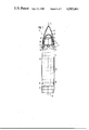
- FIG. 1 illustrates a projectile forming a small bomb-carrier, shown partly in cross-section
- FIG. 2 illustrates the carrier after the blowing off of its outer nose cone during steep approach towards the target ground.
- a small-bomb carrier is in the form of a projectile 2 which can be fired from a barreled weapon.
- the carrier consists of a projectile tip 3 with a sensor 4 and an electronic signal processing device 5, an intermediate portion 6 with an ejector propellent charge 7, a projectile shell casing 8 with an ejector plate 9, as well as a projectile base 10 with a guide band 11.
- the small bombs 15 which are to be conveyed by the projectile 2 over the target area 12, 13 (FIG. 2) and there expelled in the direction of the longitudinal axis of the projectile 14 and opposite the flying direction of the projectile, are arranged in the projectile casing 8 intermediate the ejector plate 9 and the base 10; in essence, arranged strand-like in series and packed concentrically about the longitudinal axis 14 of the projectile.
- a triggering device 16 arranged in the intermediate portion 6 is actuated by the signal processing device 5, which will ignite the ejector propellent charge 7.
- the contour of the projectile tip or nose cone 8 is defined by a smooth flow-enhancing outer nose cone 19 configuration of a high-strength material, particularly a material which is based on lightweight metals.
- the tip is screwed together at its sides with a nose cone socket 20 located at the rear of the projectile tip 3.
- the outer nose cone 19, controlled from the signal processing device 5 can be burst forwardly away from the socket 20.
- an inner nose cone 22 which is shaped as a forwardly extending hollow hemisphere, whose geometry material, in accordance with the extent of the electromagnetic radiation which the sensor 4 operates, is designed to maintain distortions and losses, encountered during the passage of radiation through the inner nose cone 22, as low as possible.
- the sensor 4 Arranged behind the inner nose cone 22 within the projectile tip 3 is the sensor 4, which is preferably formed as a very high frequency-wave parabolic mirror 23 with a central axis located within the longitudinal axis 14 of the projectile.
- the device for the conversion of electromagnetic signals which are received into information which is evaluated by the signal processing device 5 located rearwardly thereof, for initiating the explosive bursting away of the outer nose cone 19 and thereafter for the ejection of the small bombs 15.
- the carrier or canister 1 is designed, when required respectively final phase-controlled, to approach the target area in a relatively steep free-falling flight.
- the sensor 4 for the construction and assembly of the sensor 4, as previously mentioned, there need not be employed any special requirements; it is adequate to provide a receiver arrangement which is coaxially and fixedly built into the projectile tip 3 and previously oriented relative thereto, as is generally required by the parabolic mirror 23 for high-frequency waves.
- the target area 12 on the ground 25, in accordance with the measure of the fall angle and the flight movements of the carrier 1, represents a time-dependent ovally-distorted circular surface.
- This surface conforms with the dispersion area over which the small bombs or bomblets 15 will disperse at an ejection at a standard height or elevation 24 of, for example, about 300 meters above ground 25.
- the target detection through the sensor 4; for example, at a detecting height 26 of 400 meters above ground 25.
- the object of this target detection is the receiving of the reflective or inherent radiation of target objects 27 located within the detection area for the sensor which, on the ground 25, corresponds to an inner, decreased target area, on which the dispersion area of the small bombs 15 can be reduced in that the ejection of the small bombs is delayed until the reaching of a reduced or lower height 29 above ground 25.
- the small bomb ejection at this lower height 29, due to the decreased dispersion area, provides for a concentration of the small bombs 15 on the inner target area 13, and thereby on the target object 27 located therein, so that almost all small bombs 15 will attack with a high degree of density and the target will, in all probability, be forced out of action or combat.
- the effectiveness of utilizing small bombs 15 against target objects 27 can be essentially enhanced in that a simple variant of the sensor technology developed for combat observation and target detection can be employed herein for delaying of the small bomb ejection up to the reaching of a lower height 29 above ground when there is detected within the inner target area 13 a defined target object 27.
Landscapes
- Engineering & Computer Science (AREA)
- General Engineering & Computer Science (AREA)
- Chemical & Material Sciences (AREA)
- Combustion & Propulsion (AREA)
- Aiming, Guidance, Guns With A Light Source, Armor, Camouflage, And Targets (AREA)
- Radar Systems Or Details Thereof (AREA)
Applications Claiming Priority (2)
| Application Number | Priority Date | Filing Date | Title |
|---|---|---|---|
| DE19833319824 DE3319824A1 (de) | 1983-06-01 | 1983-06-01 | Verfahren zum bekaempfen von zielobjekten mittels bomblets und bomblet-traegerkoerper zum ausueben des verfahrens |
| DE3319824 | 1983-06-01 |
Publications (1)
| Publication Number | Publication Date |
|---|---|
| US4583461A true US4583461A (en) | 1986-04-22 |
Family
ID=6200390
Family Applications (1)
| Application Number | Title | Priority Date | Filing Date |
|---|---|---|---|
| US06/614,742 Expired - Fee Related US4583461A (en) | 1983-06-01 | 1984-05-25 | Method for attacking of target objects with small bombs and a small bomb-carrier for implementing the method |
Country Status (4)
| Country | Link |
|---|---|
| US (1) | US4583461A (de) |
| EP (1) | EP0127805B1 (de) |
| DE (2) | DE3319824A1 (de) |
| IL (1) | IL71729A (de) |
Cited By (10)
| Publication number | Priority date | Publication date | Assignee | Title |
|---|---|---|---|---|
| US4676167A (en) * | 1986-01-31 | 1987-06-30 | Goodyear Aerospace Corporation | Spin dispensing method and apparatus |
| US4750403A (en) * | 1986-01-31 | 1988-06-14 | Loral Corporation | Spin dispensing method and apparatus |
| US4750423A (en) * | 1986-01-31 | 1988-06-14 | Loral Corporation | Method and system for dispensing sub-units to achieve a selected target impact pattern |
| US4773328A (en) * | 1985-04-25 | 1988-09-27 | Rheinmetall Gmbh | Method of actuating a proximity fuze and device for implementing the method |
| DE3739370A1 (de) * | 1987-11-20 | 1989-06-01 | Diehl Gmbh & Co | Bomblet-gefechtskopf |
| US4848235A (en) * | 1986-09-12 | 1989-07-18 | Diehl Gmbh & Co. | Submunition member with laterally outwardly-movable target detection device |
| US4858532A (en) * | 1986-03-27 | 1989-08-22 | Aktiebolaget Bofors | Submunitions |
| US6003809A (en) * | 1997-02-25 | 1999-12-21 | Honigsbaum; Richard F. | Process and apparatus for discouraging countermeasures against a weapon transport device |
| US20040134372A1 (en) * | 2002-10-26 | 2004-07-15 | Werner Scherer | Smoke shell |
| US8141468B2 (en) | 2009-03-17 | 2012-03-27 | Raytheon Company | Adjustable bomb carrier |
Families Citing this family (3)
| Publication number | Priority date | Publication date | Assignee | Title |
|---|---|---|---|---|
| DE3414414A1 (de) * | 1984-04-17 | 1985-10-17 | Dynamit Nobel Ag, 5210 Troisdorf | Flugkoerper mit einem fernwirkenden gefechtskopf |
| DE4304058C2 (de) * | 1993-02-11 | 2002-04-18 | Diehl Stiftung & Co | Verfahren und Vorrichtung zum Bekämpfen von Zielobjekten mit Submunitionen |
| DE102004053449B4 (de) * | 2004-11-05 | 2010-12-09 | Diehl Bgt Defence Gmbh & Co. Kg | Vorsatzhaube |
Citations (10)
| Publication number | Priority date | Publication date | Assignee | Title |
|---|---|---|---|---|
| US3611931A (en) * | 1969-05-05 | 1971-10-12 | Murell J Bessey | Sequential burst air drop cluster |
| US3726223A (en) * | 1970-02-16 | 1973-04-10 | Us Navy | Adaptive warhead |
| DE2364195A1 (de) * | 1973-12-22 | 1975-06-26 | Messerschmitt Boelkow Blohm | Zielbekaempfungsverfahren fuer multi- gefechtskoepfe |
| US4072107A (en) * | 1967-06-07 | 1978-02-07 | The United States Of America As Represented By The Secretary Of The Army | Missile control means |
| US4128836A (en) * | 1960-10-14 | 1978-12-05 | The United States Of America As Represented By The Secretary Of The Army | Time delay computer for ordnance fuse |
| US4157068A (en) * | 1976-10-26 | 1979-06-05 | A/S Kongsberg Vapenfabrikk | Missile for discharge towards a target |
| US4185560A (en) * | 1962-01-31 | 1980-01-29 | Mayer Levine | Fore and aft fuzing system |
| US4320703A (en) * | 1966-05-27 | 1982-03-23 | United States Of America As Represented By The Secretary Of The Navy | Target detecting device |
| US4444117A (en) * | 1981-03-30 | 1984-04-24 | The Boeing Company | Stacked tube submunition dispenser |
| US4455943A (en) * | 1981-08-21 | 1984-06-26 | The Boeing Company | Missile deployment apparatus |
Family Cites Families (5)
| Publication number | Priority date | Publication date | Assignee | Title |
|---|---|---|---|---|
| US2961954A (en) * | 1943-02-01 | 1960-11-29 | Harry H Moore | Depth charge firing mechanism |
| US2782716A (en) * | 1953-11-30 | 1957-02-26 | North American Aviation Inc | Destructible cover for fragile dome |
| FR1203886A (fr) * | 1958-07-04 | 1960-01-21 | Aeronautique Soc Ind | Mécanisme autodirecteur à détection optique, notamment pour mobiles du type des engins spéciaux |
| FR1605069A (de) * | 1966-12-01 | 1973-01-12 | ||
| DE3038295A1 (de) * | 1980-10-10 | 1982-05-27 | Dynamit Nobel Ag, 5210 Troisdorf | Verfahren zum verteilen von gefechtskoerpern |
-
1983
- 1983-06-01 DE DE19833319824 patent/DE3319824A1/de not_active Withdrawn
-
1984
- 1984-05-02 IL IL71729A patent/IL71729A/xx unknown
- 1984-05-12 DE DE8484105385T patent/DE3465624D1/de not_active Expired
- 1984-05-12 EP EP84105385A patent/EP0127805B1/de not_active Expired
- 1984-05-25 US US06/614,742 patent/US4583461A/en not_active Expired - Fee Related
Patent Citations (10)
| Publication number | Priority date | Publication date | Assignee | Title |
|---|---|---|---|---|
| US4128836A (en) * | 1960-10-14 | 1978-12-05 | The United States Of America As Represented By The Secretary Of The Army | Time delay computer for ordnance fuse |
| US4185560A (en) * | 1962-01-31 | 1980-01-29 | Mayer Levine | Fore and aft fuzing system |
| US4320703A (en) * | 1966-05-27 | 1982-03-23 | United States Of America As Represented By The Secretary Of The Navy | Target detecting device |
| US4072107A (en) * | 1967-06-07 | 1978-02-07 | The United States Of America As Represented By The Secretary Of The Army | Missile control means |
| US3611931A (en) * | 1969-05-05 | 1971-10-12 | Murell J Bessey | Sequential burst air drop cluster |
| US3726223A (en) * | 1970-02-16 | 1973-04-10 | Us Navy | Adaptive warhead |
| DE2364195A1 (de) * | 1973-12-22 | 1975-06-26 | Messerschmitt Boelkow Blohm | Zielbekaempfungsverfahren fuer multi- gefechtskoepfe |
| US4157068A (en) * | 1976-10-26 | 1979-06-05 | A/S Kongsberg Vapenfabrikk | Missile for discharge towards a target |
| US4444117A (en) * | 1981-03-30 | 1984-04-24 | The Boeing Company | Stacked tube submunition dispenser |
| US4455943A (en) * | 1981-08-21 | 1984-06-26 | The Boeing Company | Missile deployment apparatus |
Non-Patent Citations (2)
| Title |
|---|
| "Military Microwaves '82"; Microwave Exhibitions & Pub. Ltd.; pp. 133-140, Oct. 20-22, 1982. |
| Military Microwaves 82 ; Microwave Exhibitions & Pub. Ltd.; pp. 133 140, Oct. 20 22, 1982. * |
Cited By (10)
| Publication number | Priority date | Publication date | Assignee | Title |
|---|---|---|---|---|
| US4773328A (en) * | 1985-04-25 | 1988-09-27 | Rheinmetall Gmbh | Method of actuating a proximity fuze and device for implementing the method |
| US4676167A (en) * | 1986-01-31 | 1987-06-30 | Goodyear Aerospace Corporation | Spin dispensing method and apparatus |
| US4750403A (en) * | 1986-01-31 | 1988-06-14 | Loral Corporation | Spin dispensing method and apparatus |
| US4750423A (en) * | 1986-01-31 | 1988-06-14 | Loral Corporation | Method and system for dispensing sub-units to achieve a selected target impact pattern |
| US4858532A (en) * | 1986-03-27 | 1989-08-22 | Aktiebolaget Bofors | Submunitions |
| US4848235A (en) * | 1986-09-12 | 1989-07-18 | Diehl Gmbh & Co. | Submunition member with laterally outwardly-movable target detection device |
| DE3739370A1 (de) * | 1987-11-20 | 1989-06-01 | Diehl Gmbh & Co | Bomblet-gefechtskopf |
| US6003809A (en) * | 1997-02-25 | 1999-12-21 | Honigsbaum; Richard F. | Process and apparatus for discouraging countermeasures against a weapon transport device |
| US20040134372A1 (en) * | 2002-10-26 | 2004-07-15 | Werner Scherer | Smoke shell |
| US8141468B2 (en) | 2009-03-17 | 2012-03-27 | Raytheon Company | Adjustable bomb carrier |
Also Published As
| Publication number | Publication date |
|---|---|
| EP0127805B1 (de) | 1987-08-26 |
| IL71729A (en) | 1991-05-12 |
| DE3465624D1 (en) | 1987-10-01 |
| DE3319824A1 (de) | 1984-12-06 |
| EP0127805A1 (de) | 1984-12-12 |
Similar Documents
| Publication | Publication Date | Title |
|---|---|---|
| US4050381A (en) | Low density indirect fire munition system (U) | |
| US4160415A (en) | Target activated projectile | |
| US6513438B1 (en) | Method for offering a phantom target, and decoy | |
| JP3181240B2 (ja) | 疑似標的の放出方法 | |
| US6957602B1 (en) | Parachute active protection apparatus | |
| US4583461A (en) | Method for attacking of target objects with small bombs and a small bomb-carrier for implementing the method | |
| US5668346A (en) | Submunition | |
| RU2158408C1 (ru) | Способ поражения наземных и воздушных целей и устройство (боеприпас) для его реализации | |
| US4655411A (en) | Means for reducing spread of shots in a weapon system | |
| JP5559187B2 (ja) | 二重質量の前方および側方発射型破砕弾頭 | |
| CN110145969B (zh) | 导弹拦截方法及服务器 | |
| CA1216774A (en) | Process for the distribution of submunition | |
| US4714022A (en) | Warhead with tandem shaped charges | |
| US4175491A (en) | Warhead and anti-tank missile construction | |
| US4498394A (en) | Arrangement for a terminally guided projectile provided with a target seeking arrangement and path correction arrangement | |
| US3999482A (en) | High explosive launcher system | |
| US5109774A (en) | Penetrative projectiles | |
| US3613585A (en) | High explosive antitank shell | |
| RU2034232C1 (ru) | Кассетный снаряд направленного осколочного действия | |
| US5363766A (en) | Remjet powered, armor piercing, high explosive projectile | |
| US6216597B1 (en) | Projectile having a radial direction of action | |
| US5723811A (en) | Warhead having a core generating charge | |
| USH1011H (en) | Anti-aircraft mine | |
| US3839940A (en) | Automatic pop-up decoy | |
| RU2131581C1 (ru) | Способ защиты боевой части тандемного боеприпаса и тандемный боеприпас |
Legal Events
| Date | Code | Title | Description |
|---|---|---|---|
| AS | Assignment |
Owner name: DIEHL GMBH & CO. 8500 NURNBERG WEST GERMAN A CORP Free format text: ASSIGNMENT OF ASSIGNORS INTEREST.;ASSIGNOR:WEBER, ADOLF;REEL/FRAME:004266/0501 Effective date: 19840511 Owner name: DIEHL GMBH & CO.,GERMANY Free format text: ASSIGNMENT OF ASSIGNORS INTEREST;ASSIGNOR:WEBER, ADOLF;REEL/FRAME:004266/0501 Effective date: 19840511 |
|
| FEPP | Fee payment procedure |
Free format text: PAYOR NUMBER ASSIGNED (ORIGINAL EVENT CODE: ASPN); ENTITY STATUS OF PATENT OWNER: LARGE ENTITY |
|
| FPAY | Fee payment |
Year of fee payment: 4 |
|
| REMI | Maintenance fee reminder mailed | ||
| LAPS | Lapse for failure to pay maintenance fees | ||
| FP | Lapsed due to failure to pay maintenance fee |
Effective date: 19940705 |
|
| STCH | Information on status: patent discontinuation |
Free format text: PATENT EXPIRED DUE TO NONPAYMENT OF MAINTENANCE FEES UNDER 37 CFR 1.362 |