US4595263A - Projection lens system - Google Patents
Projection lens system Download PDFInfo
- Publication number
- US4595263A US4595263A US06/628,375 US62837584A US4595263A US 4595263 A US4595263 A US 4595263A US 62837584 A US62837584 A US 62837584A US 4595263 A US4595263 A US 4595263A
- Authority
- US
- United States
- Prior art keywords
- sup
- sub
- lens
- power
- elements
- Prior art date
- Legal status (The legal status is an assumption and is not a legal conclusion. Google has not performed a legal analysis and makes no representation as to the accuracy of the status listed.)
- Expired - Lifetime
Links
- 230000003287 optical effect Effects 0.000 claims description 7
- 238000000926 separation method Methods 0.000 claims description 6
- 239000011521 glass Substances 0.000 description 5
- OAICVXFJPJFONN-UHFFFAOYSA-N Phosphorus Chemical compound [P] OAICVXFJPJFONN-UHFFFAOYSA-N 0.000 description 4
- 230000004075 alteration Effects 0.000 description 3
- 238000009125 cardiac resynchronization therapy Methods 0.000 description 3
- 238000001816 cooling Methods 0.000 description 3
- 239000004033 plastic Substances 0.000 description 3
- 229920003023 plastic Polymers 0.000 description 3
- 238000004519 manufacturing process Methods 0.000 description 2
- 238000010791 quenching Methods 0.000 description 2
- 230000000171 quenching effect Effects 0.000 description 2
- 238000009877 rendering Methods 0.000 description 2
- 238000000149 argon plasma sintering Methods 0.000 description 1
- 239000002826 coolant Substances 0.000 description 1
- 239000005357 flat glass Substances 0.000 description 1
- 238000003384 imaging method Methods 0.000 description 1
- 238000005342 ion exchange Methods 0.000 description 1
- 238000011068 loading method Methods 0.000 description 1
- 239000000463 material Substances 0.000 description 1
- 238000000034 method Methods 0.000 description 1
- 239000007787 solid Substances 0.000 description 1
- 230000003595 spectral effect Effects 0.000 description 1
Images



Classifications
-
- G—PHYSICS
- G03—PHOTOGRAPHY; CINEMATOGRAPHY; ANALOGOUS TECHNIQUES USING WAVES OTHER THAN OPTICAL WAVES; ELECTROGRAPHY; HOLOGRAPHY
- G03B—APPARATUS OR ARRANGEMENTS FOR TAKING PHOTOGRAPHS OR FOR PROJECTING OR VIEWING THEM; APPARATUS OR ARRANGEMENTS EMPLOYING ANALOGOUS TECHNIQUES USING WAVES OTHER THAN OPTICAL WAVES; ACCESSORIES THEREFOR
- G03B21/00—Projectors or projection-type viewers; Accessories therefor
- G03B21/10—Projectors with built-in or built-on screen
-
- G—PHYSICS
- G02—OPTICS
- G02B—OPTICAL ELEMENTS, SYSTEMS OR APPARATUS
- G02B13/00—Optical objectives specially designed for the purposes specified below
- G02B13/16—Optical objectives specially designed for the purposes specified below for use in conjunction with image converters or intensifiers, or for use with projectors, e.g. objectives for projection TV
-
- G—PHYSICS
- G02—OPTICS
- G02B—OPTICAL ELEMENTS, SYSTEMS OR APPARATUS
- G02B13/00—Optical objectives specially designed for the purposes specified below
- G02B13/18—Optical objectives specially designed for the purposes specified below with lenses having one or more non-spherical faces, e.g. for reducing geometrical aberration
Definitions
- This invention relates to projection lenses and, more particularly, relates to lenses designed to project an enlargement of an image on a cathode ray tube (CRT) such as a phosphor screen of a television set.
- CRT cathode ray tube
- projection CRT's are usually run at high screen loadings in order to roduce an adequately bright picture for viewing.
- the phosphor can be raised in temperature and thermal quenching of the phosphor can occur, reducing picture brightness with increasing temperature.
- the field flattener is in optical contact with the CRT face plate, the effective thickness of the face plate varies considerably across the picture, being especially thick at the picture edges. Face plate cooling is then not constant over the picture and, hence, phosphor temperature is not constant over the picture, producing brightness variations via thermal quenching.
- the field flattener may, therefore, be separated from the face plate and a coolant circulated between them, incurring additional complexity.
- the optical problem of the field flattener is largely solved by using a cathode ray tube having a face plate which is concave towards the projection lens.
- the face plate glass may be strengthened, for example by surface ion exchange, so that it can withstand atmospheric pressure on the concave surface.
- a single element lens having both surfaces aspherized is used together with a solid prism beam combiner for projecting the images from all three of the CRT's.
- the prism has convex surfaces fitting the concave CRT face plates, rendering cooling difficult.
- the invention provides a lens system for projecting an image of a concave object surface onto a planar display screen, characterized in that the projection lens comprises first and third elements, each of positive power and each having one aspheric surface, and a second element between the first and third elements, said second element having one aspheric surface, the powers of the elements being chosen so that
- K 1 is the power of the first element remote from the object surface
- K 2 is the power of the second element
- K 3 is the power of the third element adjacent to the object surface
- K is the total power of the projection lens
- each aspheric surface being defined by the following relationship: ##EQU1##
- Z is a deviation, in the axial direction, of the surface from a plane normal to the optical axis and tangent to the surface at its pole for a zone of the surface which is at a distance s from the axis
- C is a curvature of the surface on the axis
- ⁇ is a conic constant
- a 4 , a 6 , a 8 and a 10 are constants for the surface.
- Lenses in accordance with the invention can be designed to realize either the high definition required in 1249 line television with an acceptably short throw distance or the definition required in 525 or 625 line television with a particularly large projection angle and, hence, short throw distance which is desirable if the TV cabinet is to be particularly compact.
- the image may be projected onto a translucent screen from the back, the CRT and lens being behind the screen and within a free standing cabinet, the front of which comprises the screen. It is desirable to reduce the depth of the cabinet as much as possible and at least below a value such that the T.V. set can easily pass through ordinary living room doors. Folding mirrors are usually used within the cabinet to reduce the depth. Using a lens in accordance with the invention, the number of folding mirrors can be reduced because the projection distance, or throw, from the lens to the screen is reduced and because a wide projection angle is provided so that the projected picture size is maintained.
- a projection television system including a cathode ray tube having a face plate concave towards the lens system.
- a color television projection system comprising first, second and third cathode ray tubes having red, blue and green phosphors respectively provided on concave face plates, a lens system associated with each cathode ray tube, each lens system being arranged to project an image of the concave face plate onto a common display screen.
- FIG. 1 shows a typical layout of a projection television system to which a lens system in accordance with the invention may be applied
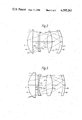
- FIG. 2 shows a lens system designed for production with the three lens elements made entirely of a plastics material and suitable for high definition television at a projection angle of ⁇ 26°,
- FIG. 3 shows a high definition lens system with glass elements
- FIG. 4 shows a medium definition lens system with glass elements having a projection angle of ⁇ 37°
- FIGS. 5, 6 and 7 show the modulation transfer functions and defocus functions of the lens systems of FIGS. 2, 3 and 4, respectively.
- a free standing cabinet 1 contains a back projection television display system comprising a cathode ray tube (CRT) 2 having a face plate concave towards a projection lens 3, front metallized folding mirrors 5 and 6 and a translucent projection screen 7.
- the screen may be a Fresnel screen and may also have a light scattering power which is less in the vertical plane than in the horizontal plane to avoid wasting projected light.
- CRTs and three lenses are used in line normal to the plane of the drawing.
- Mirrors 5, 6 are then extended in the direction normal to the drawing to accept light from all three CRTs.
- the outermost CRTs and lenses are inclined inwards so that the projected red, blue and green rasters are brought into coincidence on the screen 7.
- the projection lens 3 for such a television display system can be realized by using only three lens elements eac having one aspheric surface.
- Such a lens 3 has adequate quality for high definition 1249 line television or for 525 line or 625 line television with an exceptionally large projection angle.
- the Petzval curvature of the lens 3 fits the concave CRT face plate closely, removing the need for a field flattener.
- FIGS. 2, 3 and 4 show three different examples of the lens system having different projection angles and designed for different purposes.
- FIG. 2 is an all-plastics design, FIGS. 3 and 4 being designs with glass elements.
- the lens elements are designated by L followed by a numeral indicating the sequential position of the element from the image or projection screen end to the CRT face plate FP.
- the surfaces of the elements are designated by S followed by a numeral in the same sequence as the elements. Positive surfaces are convex towards the projection screen and negative surfaces are concave towards the projection screen.
- the powers of the three elements are within the ranges given by:
- K is the power of the whole lens equal to the reciprocal of its focal length and K 1 , K 2 and K 3 are the powers of the three elements equal to the reciprocal of their respective focal lengths, elements K 1 and K 3 always being of positive power.
- L 1 is generally convex towards the projection screen and L 3 is generally a biconvex element. All three elements have one aspheric surface for detailed aberration correction. Surfaces S2, S4 and S5 are aspherized in the three design example given below.
- the aspheric surfaces are defined by the expression ##EQU2## where Z is a deviation, in the axial direction, of the surface from a plane normal to the optical axis and tangent to the surface at its pole for a zone of the surface which is at a distance s from the axis, C is a curvature of the surface at the pole, ⁇ is a conic constant and a 4 , a 6 , a 8 and a 10 are constants for the surface.
- the first term of Z defines the basic shape of the whole surface. If ⁇ has the valve 1, the basic shape is a sphere. For parabolic, ellipsodal or hyperbolic basic shapes, ⁇ has the values 0, between 0 and 1 or less than 0, respectively.
- FIGS. 5 and 6 show the performance of the lenses of FIGS. 2 and 3, respectively.
- the column of five graphs on the right shows the modulation transfer functions (MTF) plotted vertically at various distance H off axis at the CRT face plate as a function of spatial frequency for the tangential (Tan) and sagittal (Sag) directions.
- MTF modulation transfer functions
- H the value of the effective lens aperture area P is give relative to the value on axis.
- the MTFs are plotted out to 7.5 cycles per mm on the CRT face plate rather than on the image as projected. This is because the lens design procedure traces rays from points on the projection screen onto the CRT face plate.
- the column of five graphs on the left shows the variation of the MTF as a function of defocus distance at the CRT face plate.
- the base value of the MTF is 5.0 cycles per mm. It will be seen that there is a substantial margin of about ⁇ 0.15 mm for defocus error and for face plate manufacturing tolerance. Over a diameter of 120 mm, this gives ⁇ 1 mm tolerance on face plate radius.
- FIG. 7 shows the performance of the extra wide angle, all glass design of FIG. 4.
- the base value of the MTF on the defocus curves is 2.5 cycles per mm, this lens being designed for lower definition 525/625 line T.V. If an average is taken of the tangential and sagittal MTFs, it will be seen that an MTF of 0.5 is achieved approximately at the picture edges.
- the thow distance of 0.75 m is particularly short and, combined with a projection angle of ⁇ 37.2°, permits a very compact T.V. cabinet design.
- the aspheric surface can be on either side of each element.
- the CRT face plate can have concentric surfaces or each surface can have the same radius or slightly different radii consistent with the face plate thickness remaining substantially constant or chosen so that the face plate has weak positive or negative power.
- Either face plate surface may be aspherized to further improve resolution.
Landscapes
- Physics & Mathematics (AREA)
- General Physics & Mathematics (AREA)
- Optics & Photonics (AREA)
- Lenses (AREA)
- Non-Portable Lighting Devices Or Systems Thereof (AREA)
- Projection Apparatus (AREA)
Applications Claiming Priority (2)
| Application Number | Priority Date | Filing Date | Title |
|---|---|---|---|
| GB08319940A GB2143963A (en) | 1983-07-25 | 1983-07-25 | Projection lens system |
| GB8319940 | 1983-07-25 |
Publications (1)
| Publication Number | Publication Date |
|---|---|
| US4595263A true US4595263A (en) | 1986-06-17 |
Family
ID=10546227
Family Applications (1)
| Application Number | Title | Priority Date | Filing Date |
|---|---|---|---|
| US06/628,375 Expired - Lifetime US4595263A (en) | 1983-07-25 | 1984-07-05 | Projection lens system |
Country Status (7)
| Country | Link |
|---|---|
| US (1) | US4595263A (de) |
| EP (1) | EP0135216B1 (de) |
| JP (1) | JPH0646260B2 (de) |
| AT (1) | ATE47234T1 (de) |
| CA (1) | CA1230248A (de) |
| DE (1) | DE3480124D1 (de) |
| GB (1) | GB2143963A (de) |
Cited By (9)
| Publication number | Priority date | Publication date | Assignee | Title |
|---|---|---|---|---|
| US4682862A (en) * | 1986-01-17 | 1987-07-28 | U.S. Precision Lens Incorporated | Projection lens |
| US4699477A (en) * | 1984-12-14 | 1987-10-13 | U.S. Philips Corporation | Projection lens system |
| US4722593A (en) * | 1985-07-29 | 1988-02-02 | Casio Computer Co., Ltd. | Liquid-crystal projector with light beam reduction lens array for improved brightness of image outer portions |
| WO1988003347A1 (en) * | 1986-10-27 | 1988-05-05 | Tds Patent Management, Inc. | Aplanatic image combiner for use in projection television systems |
| US4776681A (en) * | 1986-01-17 | 1988-10-11 | U.S. Precision Lens, Incorporated | Projection lens |
| US4842394A (en) * | 1988-02-18 | 1989-06-27 | Tds Patent Management, Inc. | Simplified high speed corrected projection lens system for curved image surfaces |
| US4875763A (en) * | 1985-12-11 | 1989-10-24 | Minolta Camera Kabushiki Kaisha | Video projector lens system |
| US5991088A (en) * | 1996-06-04 | 1999-11-23 | Canon Kabushiki Kaisha | Illumination system and exposure apparatus |
| EP0989449A3 (de) * | 1994-01-28 | 2000-04-05 | Matsushita Electric Industrial Co., Ltd. | Optisches System für Rückprojektionsgerät |
Families Citing this family (7)
| Publication number | Priority date | Publication date | Assignee | Title |
|---|---|---|---|---|
| JPS6271915A (ja) * | 1985-09-25 | 1987-04-02 | Hitachi Ltd | 投写形テレビ用光学系 |
| US5692820A (en) * | 1992-02-20 | 1997-12-02 | Kopin Corporation | Projection monitor |
| US5467154A (en) * | 1992-02-20 | 1995-11-14 | Kopin Corporation | Projection monitor |
| USRE38488E1 (en) * | 1994-01-28 | 2004-04-06 | Matsushita Electric Industrial Co., Ltd. | Optical system including a reflecting polarizer for a rear projection picture display apparatus |
| BE1009592A4 (nl) * | 1995-09-12 | 1997-05-06 | Barco Nv | Beeldweergaveinrichting en werkwijze voor het weergeven van een beeld. |
| BE1009596A6 (nl) * | 1995-09-12 | 1997-05-06 | Barco Nv | Beeldweergaveinrichting en werkwijze voor het weergeven van een beeld. |
| CN103901712B (zh) * | 2012-12-28 | 2016-12-28 | 台达电子工业股份有限公司 | 虚像显示系统 |
Citations (3)
| Publication number | Priority date | Publication date | Assignee | Title |
|---|---|---|---|---|
| US4163604A (en) * | 1977-12-23 | 1979-08-07 | U.S. Precision Lens, Inc. | Projection lens |
| GB2091898A (en) * | 1981-01-23 | 1982-08-04 | Hodges Marvin P | Aspheric projection lens system utilizing concave image |
| US4496223A (en) * | 1981-11-04 | 1985-01-29 | Polaroid Corporation | Compact afocal attachment for use with photographic objectives |
Family Cites Families (3)
| Publication number | Priority date | Publication date | Assignee | Title |
|---|---|---|---|---|
| US2430150A (en) * | 1942-08-25 | 1947-11-04 | Taylor Taylor & Hobson Ltd | Optical objective |
| US4109995A (en) * | 1976-06-03 | 1978-08-29 | Opcon Associates Of Canada, Ltd. | Triplet with aspheric surfaces |
| US4448504A (en) * | 1981-11-18 | 1984-05-15 | Industrial Electronic Engineers, Inc. | Rear end projection system employing aspherical lenses |
-
1983
- 1983-07-25 GB GB08319940A patent/GB2143963A/en not_active Withdrawn
-
1984
- 1984-07-05 US US06/628,375 patent/US4595263A/en not_active Expired - Lifetime
- 1984-07-12 DE DE8484201040T patent/DE3480124D1/de not_active Expired
- 1984-07-12 AT AT84201040T patent/ATE47234T1/de not_active IP Right Cessation
- 1984-07-12 EP EP84201040A patent/EP0135216B1/de not_active Expired
- 1984-07-19 CA CA000459295A patent/CA1230248A/en not_active Expired
- 1984-07-25 JP JP59153325A patent/JPH0646260B2/ja not_active Expired - Lifetime
Patent Citations (3)
| Publication number | Priority date | Publication date | Assignee | Title |
|---|---|---|---|---|
| US4163604A (en) * | 1977-12-23 | 1979-08-07 | U.S. Precision Lens, Inc. | Projection lens |
| GB2091898A (en) * | 1981-01-23 | 1982-08-04 | Hodges Marvin P | Aspheric projection lens system utilizing concave image |
| US4496223A (en) * | 1981-11-04 | 1985-01-29 | Polaroid Corporation | Compact afocal attachment for use with photographic objectives |
Cited By (10)
| Publication number | Priority date | Publication date | Assignee | Title |
|---|---|---|---|---|
| US4699477A (en) * | 1984-12-14 | 1987-10-13 | U.S. Philips Corporation | Projection lens system |
| US4722593A (en) * | 1985-07-29 | 1988-02-02 | Casio Computer Co., Ltd. | Liquid-crystal projector with light beam reduction lens array for improved brightness of image outer portions |
| US4875763A (en) * | 1985-12-11 | 1989-10-24 | Minolta Camera Kabushiki Kaisha | Video projector lens system |
| US4682862A (en) * | 1986-01-17 | 1987-07-28 | U.S. Precision Lens Incorporated | Projection lens |
| US4776681A (en) * | 1986-01-17 | 1988-10-11 | U.S. Precision Lens, Incorporated | Projection lens |
| WO1988003347A1 (en) * | 1986-10-27 | 1988-05-05 | Tds Patent Management, Inc. | Aplanatic image combiner for use in projection television systems |
| US4764806A (en) * | 1986-10-27 | 1988-08-16 | Tds Patent Management, Inc. | Aplanatic image combiner for use in projection television systems with reduced spherical and coma aberration |
| US4842394A (en) * | 1988-02-18 | 1989-06-27 | Tds Patent Management, Inc. | Simplified high speed corrected projection lens system for curved image surfaces |
| EP0989449A3 (de) * | 1994-01-28 | 2000-04-05 | Matsushita Electric Industrial Co., Ltd. | Optisches System für Rückprojektionsgerät |
| US5991088A (en) * | 1996-06-04 | 1999-11-23 | Canon Kabushiki Kaisha | Illumination system and exposure apparatus |
Also Published As
| Publication number | Publication date |
|---|---|
| DE3480124D1 (en) | 1989-11-16 |
| EP0135216A1 (de) | 1985-03-27 |
| ATE47234T1 (de) | 1989-10-15 |
| CA1230248A (en) | 1987-12-15 |
| GB2143963A (en) | 1985-02-20 |
| EP0135216B1 (de) | 1989-10-11 |
| JPH0646260B2 (ja) | 1994-06-15 |
| JPS6043627A (ja) | 1985-03-08 |
| GB8319940D0 (en) | 1983-08-24 |
Similar Documents
| Publication | Publication Date | Title |
|---|---|---|
| EP0135216B1 (de) | Projektionslinsensystem | |
| US5760965A (en) | Wide-projection angle liquid crystal projection lens system | |
| EP0457404B1 (de) | Farbprojektor mit kurzer Brennweite, der eine dichroitische Spiegeleinheit enthält | |
| KR20010021697A (ko) | 고성능 투사 텔레비젼 렌즈 시스템 | |
| US4699476A (en) | Projection lens system | |
| US4933599A (en) | Projection system with a cathode ray tube and a lens | |
| EP0184879B1 (de) | Projektionslinsensystem | |
| US4573769A (en) | Projection lens system | |
| US5016994A (en) | Projection-lens system | |
| JPH0151809B2 (de) | ||
| US4872748A (en) | Projection-lens system | |
| US4884879A (en) | Lens system for projection television receivers | |
| US4842394A (en) | Simplified high speed corrected projection lens system for curved image surfaces | |
| JPS61205909A (ja) | 投写形テレビ用光学系 | |
| US4163604A (en) | Projection lens | |
| Clarke | Current trends in optics for projection TV | |
| KR20060129132A (ko) | 투사 광학계 및 이를 채용한 프로젝션 tv | |
| Osawa et al. | Optical design of high-aperture aspherical projection lens | |
| Clarke | Wide angle lenses for projection TV |
Legal Events
| Date | Code | Title | Description |
|---|---|---|---|
| AS | Assignment |
Owner name: U.S. PHILIPS CORPORATION 100 EAST 42ND STREET NEW Free format text: ASSIGNMENT OF ASSIGNORS INTEREST.;ASSIGNOR:CLARKE, JOHN A.;REEL/FRAME:004318/0406 Effective date: 19840920 |
|
| STCF | Information on status: patent grant |
Free format text: PATENTED CASE |
|
| CC | Certificate of correction | ||
| FEPP | Fee payment procedure |
Free format text: PAYOR NUMBER ASSIGNED (ORIGINAL EVENT CODE: ASPN); ENTITY STATUS OF PATENT OWNER: LARGE ENTITY |
|
| FPAY | Fee payment |
Year of fee payment: 4 |
|
| FPAY | Fee payment |
Year of fee payment: 8 |
|
| FPAY | Fee payment |
Year of fee payment: 12 |