US4597181A - Planing tool having a quickly releasable rotary planer head - Google Patents
Planing tool having a quickly releasable rotary planer head Download PDFInfo
- Publication number
- US4597181A US4597181A US06/609,221 US60922184A US4597181A US 4597181 A US4597181 A US 4597181A US 60922184 A US60922184 A US 60922184A US 4597181 A US4597181 A US 4597181A
- Authority
- US
- United States
- Prior art keywords
- planer head
- bearing
- head
- bearing journals
- planer
- Prior art date
- Legal status (The legal status is an assumption and is not a legal conclusion. Google has not performed a legal analysis and makes no representation as to the accuracy of the status listed.)
- Expired - Fee Related
Links
Images


Classifications
-
- B—PERFORMING OPERATIONS; TRANSPORTING
- B23—MACHINE TOOLS; METAL-WORKING NOT OTHERWISE PROVIDED FOR
- B23Q—DETAILS, COMPONENTS, OR ACCESSORIES FOR MACHINE TOOLS, e.g. ARRANGEMENTS FOR COPYING OR CONTROLLING; MACHINE TOOLS IN GENERAL CHARACTERISED BY THE CONSTRUCTION OF PARTICULAR DETAILS OR COMPONENTS; COMBINATIONS OR ASSOCIATIONS OF METAL-WORKING MACHINES, NOT DIRECTED TO A PARTICULAR RESULT
- B23Q1/00—Members which are comprised in the general build-up of a form of machine, particularly relatively large fixed members
- B23Q1/70—Stationary or movable members for carrying working-spindles for attachment of tools or work
-
- B—PERFORMING OPERATIONS; TRANSPORTING
- B27—WORKING OR PRESERVING WOOD OR SIMILAR MATERIAL; NAILING OR STAPLING MACHINES IN GENERAL
- B27C—PLANING, DRILLING, MILLING, TURNING OR UNIVERSAL MACHINES FOR WOOD OR SIMILAR MATERIAL
- B27C1/00—Machines for producing flat surfaces, e.g. by rotary cutters; Equipment therefor
- B27C1/10—Hand planes equipped with power-driven cutter blocks
Definitions
- the invention concerns a planing tool of the type having an electric motor for driving a rotary planer head.
- the motor is connected with a drive wheel joined for rotation with a drive shaft, the latter being radially and axially supported in bearings in the housing of the planer head.
- Known manual or hand-held planing tools were heretofore suitable exclusively for the smooth planing of surfaces and for fitting work, for example of window frames in wall openings or for the planing of doors at the floor level. Rabbets could also be finished-planed.
- the feed table or the chip thickness limiter of the known manual planing tools are adjustable in a plane parallel with respect to the guide or discharge plate.
- the discharge plate is generally set exactly tangent to the circle of rotation of the planer cutters and is thus not adjustable.
- the planar structure of the workpiece to be processed is therefore not altered. Even in the case of the so-called rough plane or the barrel plane, which represent to a certain extent an exception to the general structure of such tools, the planar character of the workpiece remains essentially unchanged.
- a shaping or profiling of wood such as required in the making of molding strip, picture frames, contoured panelings of any type and molded covering boards, cannot be effected with such manual planer tools.
- work is performed essentially on large, stationary special milling machines, etc., which are capable of producing standard commercial profiles or molded boards only.
- Special molding strips are, at the present time, produced manually on conventional milling machines in a relatively expensive manner. This requires specialized guiding means.
- an object of the present invention to provide a planing tool of the afore-mentioned type wherein the replacement of the planer head is readily possible, so that planer heads intended specifically for molding may be interchanged in keeping with the type of profile to be produced.
- the planer head is designed as a structural part independent of the drive shaft, and has a continuous axial bore.
- the drive shaft comprises a bearing journal provided with an axial bore and a socket pin, which is inserted into the axial bores to secure the planer head.
- the socket pin in the form of a threaded bolt connecting the bearing journal located on one side of the housing with a second bearing journal supported in the other side of the housing. This results in a stable, bilateral support.
- the second bearing journal with a stop for the planer head and with threading for the connection of the threaded bolt equipped with a head on its side facing away from the threads.
- a structurally simple configuration is obtained by equipping the bearing journal associated with the drive wheel with an axial bore and holding it in a fixed bearing and making the second bearing journal axially displaceable in its bearing location. Further advantages are achieved, such as an accurate but rapid alignment of the planer head; overload security is also attained in a simple manner, preventing damage to parts of the manual plane.
- FIG. 1 depicts a schematic lateral elevation of a manual plane according to the invention, driven by an electric motor;
- FIG. 2 is a partially broken-away top view of the manual plane of FIG. 1;
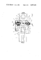
- FIG. 3 is a section through the manual plane of FIG. 2 along the line III--III;
- FIG. 4 is a cross-section through a bearing journal of the manual plane of FIG. 4;
- FIG. 5 is a section similar to that of FIG. 3, but with the planer head removed;
- FIG. 6 is a lateral elevation of the removed planer head
- FIG. 7 is a section similar to that of FIG. 3, but showing a different embodiment of a manual plane according to the present invention.
- FIG. 8 depicts the dismantled planer head of the embodiment of FIG. 7;
- FIG. 9 depicts the manual plane of FIG. 7 in a position with the planer head dismantled
- FIG. 10 depicts a section similar to that of FIG. 3, but of a further embodiment of a manual plane according to the present invention.
- FIG. 11 depicts the manual plane of FIG. 10 with the planer head dismantled
- FIG. 12 depicts a section taken along line XII--XII in FIG. 10.
- a planer head 2 in a housing 1 of a manual or hand-held plane, a planer head 2 is supported rotatingly.
- the planer head is connected for rotation with a drive wheel 3 which is rotated by means of a drive belt 4 by a pinion 5 of an electric motor 6.
- the planer head 2 is connected for rotation with a bearing journal 7, which in turn, is arranged rotatingly in a ball bearing 8 located in the housing 1.
- the journal 7 is joined for rotation with the drive wheel 3, for example, by means of a multiple key wedge connection 9.
- the plane head 2 rotated in this manner may thus be displaced, in a fashion known in itself, with the aid of the manual handle 10 of a manual knob 11, together with the housing 1 of the manual plane on a support surface 12 for the working process.
- the planer head 2 which may be equipped for example with a molding cutter 13, is not itself connected directly to a one-piece drive shaft. Rather, the drive shaft is, in the embodiment shown, in the form of an assembly comprising the bearing journal 7, a second bearing journal 14 disposed on the side of the housing opposite to the bearing 8 and a threaded rod bolt 15 connecting the two bearing journals with each other and with the planer head 2.
- the bolt 15 has a threaded free end 15a screwed into an internal thread 14a of the bearing journal 14.
- the threaded bolt 15 has a head 15b with an inner hexagonal recess. The head abuts against an outwardly facing frontal surface of the bearing journal 7.
- the bearing journal 14 has a centering cone 14c corresponding to a similar centering cone 7c of the bearing journal 7.
- the centering cones 7c, 14c engage recesses 2a in the planer head 2 which correspond in shape to the centering cones.
- the bearing journal 14 also has at its outwardly directed end an internal hexagon socket and is maintained displaceably in a needle bearing 16. If, therefore, the threaded bolt 15 is screwed into the bearing journal 14, then the cone 7c and the cone 14c, are pressed into, respectively, the corresponding recesses 2a of the planer head 2, the latter thus being secured axially in the housing 1.
- the bearing journal 7 is held axially in the fixed bearing 8.
- the bearing journal 7 is provided, over a part of its length (FIG. 4), with a hexagonal outer contour.
- a hexagonal sleeve 17 having a corresponding hexagonal configuration is slid over this area, which at its end facing the planer head 2 includes a flange in the form of a corrugated ring 18.
- This corrugated ring is positively connected, via the corrugations, with a corrugated ring 19 (see FIG. 6) of a similar corrugation, the latter being solidly joined with an annular flange 20.
- the flange 20 is connected by means of a journal 21 for rotation with the planer head 2 (FIG. 6).
- the sleeve is pressed by two flat springs 22 which abut a shoulder 17a of the sleeve 17 which interconnects the corrugated ring 18 with a cylindrical portion of the sleeve.
- the springs 22 press the sleeve against the corrugated ring 19.
- the flat springs 22 rest against a washer 23 of the stationary bearing 8.
- the drive connection has the advantage that the torque to be transmitted by the corrugated ring coupling from the drive wheel 3 to the planer head 2 may be limited to a certain value, above which value the corrugated rings become disengaged against the force of the flat springs 22, so that further rotation of the planer head 2 is prevented.
- planer head 2 may be removed in a very simple and rapid manner from the plane housing 1 by releasing the threaded bolt 15, as shown in FIG. 5, from the bearing journal 14.
- the bearing journal 14 is then extracted to the right into a recess 24 of the housing 1 until the stop of the cone 14c bottoms-out, so that the planer head may be removed and replaced by another one.
- the planer head is then moved to the right and removed together with the corrugated ring 19 (FIG. 6).
- the new planer head to be installed may be equipped with a new corrugated ring. Of course, the replacement of the corrugated ring is also possible.
- FIGS. 7, 8 and 9 show a further preferred embodiment of the invention, wherein instead of a corrugated ring, another type of slip coupling is provided.
- An insertion bolt 27 passing through the planer head 2 is in the form of a single piece along with the bearing journal 14'.
- the journal bearing 14' includes an axial stop 25 from which the bearing 14' extends, with reduced diameter, into the bearing journal 7'.
- the latter has, similarly to that of FIGS. 1 to 6, an axial bore 7a, which is aligned with the axial bore 2c of the planer head 2.
- a cap screw 26 is inserted through the axial bore 7a and connected with an internal thread 14'a of the part 27 to axially immobilize the planer head 2 between the bearing parts 7' and 14'.
- planer head 2 can be easily removed by (i) unscrewing the cap 26, (ii) sliding the journal 27, 14' to the right, (iii) sliding the planer head 2 to the right, and (iv) removing the planer head 2 from the chamber in which it sits.
- FIGS. 10 to 12 show a further possibility of effecting a rapid replacement of the planer head 2.
- the bearing journal 7" is not provided with an axial bore; instead, the bearing journal 14" is in the form of a bearing sleeve.
- a threaded bolt 28 is inserted through the bearing sleeve 14", which engages, through the planer head 2', a thread arranged in a blind hole 29 in the journal bearing 7".
- the bolt 28, with its stop 30 presses the bearing sleeve 14" and the planer head 2' against the journal bearing 7" seated in the stationary bearing 8.
- the bearing 7" abuts the planer head with its front pointing to the right.
- a sleeve 31 is inserted into the planer head 2' and a part of the bearing journal 7", the sleeve being equipped with two opposing ribs 32, which positively engage the corresponding grooves in the plane head 2' and the bearing journal 7".
- the rotating motion actuated by the drive wheel 31 through the muliple key wedge joint 9 is therefore transmitted by the sleeve 31 positively locked in it to the planer head 2'.
Landscapes
- Engineering & Computer Science (AREA)
- Mechanical Engineering (AREA)
- Life Sciences & Earth Sciences (AREA)
- Wood Science & Technology (AREA)
- Forests & Forestry (AREA)
- Milling, Drilling, And Turning Of Wood (AREA)
- Gears, Cams (AREA)
- Manipulator (AREA)
- Table Devices Or Equipment (AREA)
- Inorganic Insulating Materials (AREA)
Applications Claiming Priority (2)
| Application Number | Priority Date | Filing Date | Title |
|---|---|---|---|
| DE3318745A DE3318745C2 (de) | 1983-05-24 | 1983-05-24 | Hobelmaschine, insbesondere Handhobel |
| DE3318745 | 1983-05-24 |
Publications (1)
| Publication Number | Publication Date |
|---|---|
| US4597181A true US4597181A (en) | 1986-07-01 |
Family
ID=6199705
Family Applications (1)
| Application Number | Title | Priority Date | Filing Date |
|---|---|---|---|
| US06/609,221 Expired - Fee Related US4597181A (en) | 1983-05-24 | 1984-05-11 | Planing tool having a quickly releasable rotary planer head |
Country Status (5)
| Country | Link |
|---|---|
| US (1) | US4597181A (de) |
| EP (1) | EP0126284B1 (de) |
| JP (1) | JPS59225901A (de) |
| AT (1) | ATE36265T1 (de) |
| DE (2) | DE3318745C2 (de) |
Cited By (3)
| Publication number | Priority date | Publication date | Assignee | Title |
|---|---|---|---|---|
| US6790134B2 (en) | 2000-06-19 | 2004-09-14 | Black & Decker Inc. | Power tool |
| US20220305567A1 (en) * | 2021-03-25 | 2022-09-29 | William B. Dannehl | Repair Tool And Method |
| US12589518B2 (en) | 2022-04-25 | 2026-03-31 | Milwaukee Electric Tool Corporation | Hand-held planning tool |
Families Citing this family (2)
| Publication number | Priority date | Publication date | Assignee | Title |
|---|---|---|---|---|
| DE3617004A1 (de) * | 1986-05-21 | 1987-11-26 | Weinig Michael Gmbh Co Kg | Maschine, vorzugsweise kehlmaschine |
| CN109304765A (zh) * | 2017-07-28 | 2019-02-05 | 金华市强宏板式家具机械有限公司 | 一种抽屉式压刨机刨刀总成 |
Citations (6)
| Publication number | Priority date | Publication date | Assignee | Title |
|---|---|---|---|---|
| US1182117A (en) * | 1915-11-24 | 1916-05-09 | John Deo Tillman | Lawn-mower. |
| US1899204A (en) * | 1931-10-29 | 1933-02-28 | John G Matthews | Butcher's block planer and cleaner |
| US2233998A (en) * | 1938-06-27 | 1941-03-04 | Louis M Evjen | Rotating saw plane |
| US2540258A (en) * | 1945-08-14 | 1951-02-06 | Thomas J Harris | Hand-operated electric powered dresser |
| US2649873A (en) * | 1948-10-01 | 1953-08-25 | Reich Maschf Gmbh Karl | Electrically driven hand planing machine |
| US2719553A (en) * | 1951-05-22 | 1955-10-04 | Lillie Ballard | Portable power plane |
Family Cites Families (2)
| Publication number | Priority date | Publication date | Assignee | Title |
|---|---|---|---|---|
| DE873134C (de) * | 1951-10-30 | 1953-04-09 | Ludwig Roemer K G | Handhobel mit elektromotorisch angetriebenem, auswechselbarem Hobelkopf |
| US3407857A (en) * | 1966-12-30 | 1968-10-29 | Rockwell Mfg Co | Plane |
-
1983
- 1983-05-24 DE DE3318745A patent/DE3318745C2/de not_active Expired
-
1984
- 1984-04-13 EP EP84104187A patent/EP0126284B1/de not_active Expired
- 1984-04-13 AT AT84104187T patent/ATE36265T1/de not_active IP Right Cessation
- 1984-04-13 DE DE8484104187T patent/DE3473244D1/de not_active Expired
- 1984-05-11 US US06/609,221 patent/US4597181A/en not_active Expired - Fee Related
- 1984-05-23 JP JP59102758A patent/JPS59225901A/ja active Pending
Patent Citations (6)
| Publication number | Priority date | Publication date | Assignee | Title |
|---|---|---|---|---|
| US1182117A (en) * | 1915-11-24 | 1916-05-09 | John Deo Tillman | Lawn-mower. |
| US1899204A (en) * | 1931-10-29 | 1933-02-28 | John G Matthews | Butcher's block planer and cleaner |
| US2233998A (en) * | 1938-06-27 | 1941-03-04 | Louis M Evjen | Rotating saw plane |
| US2540258A (en) * | 1945-08-14 | 1951-02-06 | Thomas J Harris | Hand-operated electric powered dresser |
| US2649873A (en) * | 1948-10-01 | 1953-08-25 | Reich Maschf Gmbh Karl | Electrically driven hand planing machine |
| US2719553A (en) * | 1951-05-22 | 1955-10-04 | Lillie Ballard | Portable power plane |
Cited By (3)
| Publication number | Priority date | Publication date | Assignee | Title |
|---|---|---|---|---|
| US6790134B2 (en) | 2000-06-19 | 2004-09-14 | Black & Decker Inc. | Power tool |
| US20220305567A1 (en) * | 2021-03-25 | 2022-09-29 | William B. Dannehl | Repair Tool And Method |
| US12589518B2 (en) | 2022-04-25 | 2026-03-31 | Milwaukee Electric Tool Corporation | Hand-held planning tool |
Also Published As
| Publication number | Publication date |
|---|---|
| DE3318745A1 (de) | 1984-11-29 |
| DE3473244D1 (en) | 1988-09-15 |
| EP0126284B1 (de) | 1988-08-10 |
| DE3318745C2 (de) | 1986-12-04 |
| ATE36265T1 (de) | 1988-08-15 |
| JPS59225901A (ja) | 1984-12-19 |
| EP0126284A1 (de) | 1984-11-28 |
Similar Documents
| Publication | Publication Date | Title |
|---|---|---|
| US4597181A (en) | Planing tool having a quickly releasable rotary planer head | |
| CN103786053B (zh) | 一种手自一体直角头 | |
| CN114160822A (zh) | 一种襟翼滑轨加工工艺及切削加工刀具 | |
| CN116787228A (zh) | 一种高稳定性的警用制品精加工机床及其使用方法 | |
| CN102189302B (zh) | 丝锥过载保护装置 | |
| US2364065A (en) | Gear shaping machine | |
| CN214561651U (zh) | 一种可伸缩自调距刀具 | |
| CN206824765U (zh) | 一种环状端面反刮刀及反刮刀具 | |
| US2556415A (en) | Dowel cutter | |
| US4125042A (en) | Positive adjust driving center | |
| US4505627A (en) | Polygon box tool milling cutter applied to automatic screw machines | |
| US4572259A (en) | Planing tool and cutter therefor | |
| CN211276560U (zh) | 一种圆棒旋切刀具装置 | |
| CN214023766U (zh) | 可换刀架坡口机 | |
| US4819924A (en) | Heavy duty vise | |
| CN222289025U (zh) | 轴类磨齿加工用夹具 | |
| CN114871484B (zh) | 一种圆柱形铣刀及其定位装置 | |
| CN216575579U (zh) | 一种轮毂加工外圆正面一体式刀杆 | |
| CN218016214U (zh) | 一种蜗杆滚刀 | |
| CN113427584A (zh) | 条料侧面铣削及压料限位装置 | |
| CN112355844A (zh) | 一种铣刀加工用粗料钢打磨装置 | |
| CN208437706U (zh) | 一种钻孔工装 | |
| CN220216839U (zh) | 一种导头可更换式机用大孔径孔锪窝工具 | |
| CN216882069U (zh) | 手持式切削机 | |
| CN223198667U (zh) | 一种切削力度可调的刀头 |
Legal Events
| Date | Code | Title | Description |
|---|---|---|---|
| AS | Assignment |
Owner name: BLACK & DECKER OVERSEAS AG, VADUZ/LIECHTENSTEIN, L Free format text: ASSIGNMENT OF ASSIGNORS INTEREST.;ASSIGNOR:BERGLER, OTTO;REEL/FRAME:004367/0382 Effective date: 19850128 |
|
| FPAY | Fee payment |
Year of fee payment: 4 |
|
| FEPP | Fee payment procedure |
Free format text: PAYOR NUMBER ASSIGNED (ORIGINAL EVENT CODE: ASPN); ENTITY STATUS OF PATENT OWNER: LARGE ENTITY |
|
| FPAY | Fee payment |
Year of fee payment: 8 |
|
| REMI | Maintenance fee reminder mailed | ||
| LAPS | Lapse for failure to pay maintenance fees | ||
| FP | Lapsed due to failure to pay maintenance fee |
Effective date: 19980701 |
|
| STCH | Information on status: patent discontinuation |
Free format text: PATENT EXPIRED DUE TO NONPAYMENT OF MAINTENANCE FEES UNDER 37 CFR 1.362 |