US4630337A - Apparatus for doubling a fiber web - Google Patents
Apparatus for doubling a fiber web Download PDFInfo
- Publication number
- US4630337A US4630337A US06/656,673 US65667384A US4630337A US 4630337 A US4630337 A US 4630337A US 65667384 A US65667384 A US 65667384A US 4630337 A US4630337 A US 4630337A
- Authority
- US
- United States
- Prior art keywords
- web
- diverter
- transport means
- plate arrangement
- possesses
- Prior art date
- Legal status (The legal status is an assumption and is not a legal conclusion. Google has not performed a legal analysis and makes no representation as to the accuracy of the status listed.)
- Expired - Fee Related
Links
Images


Classifications
-
- D—TEXTILES; PAPER
- D01—NATURAL OR MAN-MADE THREADS OR FIBRES; SPINNING
- D01H—SPINNING OR TWISTING
- D01H5/00—Drafting machines or arrangements ; Threading of roving into drafting machine
- D01H5/18—Drafting machines or arrangements without fallers or like pinned bars
- D01H5/70—Constructional features of drafting elements
-
- B—PERFORMING OPERATIONS; TRANSPORTING
- B65—CONVEYING; PACKING; STORING; HANDLING THIN OR FILAMENTARY MATERIAL
- B65H—HANDLING THIN OR FILAMENTARY MATERIAL, e.g. SHEETS, WEBS, CABLES
- B65H57/00—Guides for filamentary materials; Supports therefor
-
- D—TEXTILES; PAPER
- D01—NATURAL OR MAN-MADE THREADS OR FIBRES; SPINNING
- D01G—PRELIMINARY TREATMENT OF FIBRES, e.g. FOR SPINNING
- D01G21/00—Combinations of machines, apparatus, or processes, e.g. for continuous processing
-
- B—PERFORMING OPERATIONS; TRANSPORTING
- B65—CONVEYING; PACKING; STORING; HANDLING THIN OR FILAMENTARY MATERIAL
- B65H—HANDLING THIN OR FILAMENTARY MATERIAL, e.g. SHEETS, WEBS, CABLES
- B65H2701/00—Handled material; Storage means
- B65H2701/30—Handled filamentary material
- B65H2701/31—Textiles threads or artificial strands of filaments
Definitions
- the present invention relates to a new and improved construction of apparatus for doubling of fiber webs.
- the fiber web-doubling apparatus of the present development is of the type comprising web transport means, a web collecting or collector element, and a so-called diverter plate arrangement for deflecting or turning the web from the transport or conveying direction of the web transport means into the transport or conveying direction of the web collecting element.
- Doubling that is superposing fiber webs so as to form a new single web, serves for evening these webs with regard to length and to the blend of the staple fibers which form the web.
- Apparatuses of the aforementioned type which serve for such doubling operations are primarily used on so-called ribbon lap machines which are commercially known from spinning machines.
- ribbon lap machines a plurality of laps arranged adjacent one another supply their respective fiber webs into a drafting mechanism where the web is drawn and is thereafter immediately guided over a so-called diverter plate arrangement.
- the apparatus can be used on so-called sliver lap machines which bring together a plurality of drawn fiber slivers into a web and double these individual web so as to form a new web.
- Such a sliver lap machine has been disclosed in Swiss Pat. No. 375,640, granted Feb. 29, 1964 and the corresponding U.S. Pat. No. 3,128,506, granted Apr. 14, 1964.
- This sliver lap machine comprises fiber sliver drafting mechanisms arranged next to one another and to which there are delivered fiber slivers from sliver cans or the like.
- the fiber slivers which are drawn in the drafting mechanisms are combined or amalgamated into a web and following each drafting mechanism are guided by means of a diverter plate arrangement on to a collecting surface for all of the webs.
- the diverter plate arrangement is arranged adjoining the drafting mechanism viewed with respect to the transport direction of the web.
- the individual webs, collected to form a new web are guided to a wind-up apparatus for the formation of a lap.
- the previously discussed ribbon lap machines have a construction resembling that of the sliver lap machines except that laps are used as the web feed in place of the sliver cans delivering fiber slivers.
- the individual drafting mechanisms do not draw fiber slivers, as is the case for the sliver lap machines, but webs delivered by the lap.
- the individual drawn webs are collected so as to form a new web in the same manner as in the sliver lap machines and are also guided to a wind-up apparatus for the formation of a lap.
- the laps of the ribbon lap machines thereafter serve as the feed or stock for the combing machines.
- the described construction of the sliver lap machine, and also that of the ribbon lap machine, is afflicted with the drawback that due to the disposition of the diverter plate arrangement in front of the drafting mechanism, as viewed from the service side of the machine, leading in of the staple fiber slivers or lap ribbons, as the case may be, cannot be carried out unless the machine attendant or operator first guides the staple fiber slivers or the webs into the infeed rolls of the drafting mechanism from the back of the machine and thereafter seizes or catches at the front of the machine the webs delivered from the drafting mechanisms and guides them over the diverter plate arrangement.
- Another and more specific object of the present invention aims at simplifying the aforementioned operating procedure which complicates starting-up of the machines.
- the fiber web-doubling apparatus of the present development is manifested by the features that a web diverter is provided between the web transport means and the diverter plate arrangement in such a manner that the diverter plate arrangement can be located beneath the web transport means.
- Certain of the more notable advantages achieved by the present invention reside in the fact that due to the provision of the diverter plate arrangement underneath the drafting mechanism the machine is less wide or deep, so that the operator can carry out leading-in of the fiber slivers or webs also from the service side. Furthermore, primarily for the so-called ribbon lap machine there results the advantage that due to the possibility of servicing or operating upon the drafting mechanism from the front side of the machine the laps can be provided on the upper side of the machine, in contrast to the known prior art arrangement where the laps are located at the back of the machine.
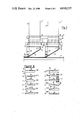
- FIG. 1 illustrates partially schematically a section through a ribbon lap machine taken substantially along the line I--I of FIG. 2;
- FIG. 2 is a top plan view, in section and illustrated partially schematically, of the ribbon lap machine depicted in FIG. 1, taken substantially along the line II--II thereof;
- FIG. 3 illustrates the ribbon lap machine of FIG. 1, partially schematically depicted, and looking in the direction of the arrow III, in other words, viewed from the service or front side of the machine;
- FIG. 4 is a sectional view, similar to the showing of FIG. 1, depicting a modification of a detail of the ribbon lap machine depicted in FIG. 1;
- FIG. 5 illustrates on a reduced scale and partially schematically a top plan view of the ribbon lap machine illustrated in FIG. 1;
- FIG. 6 illustrates in the same scale as in the arrangement of FIG. 5 a top plan view of a sliver lap machine
- FIG. 7 is a sectional view through the sliver lap machine of FIG. 6, taken along the line IV--IV thereof and shown on an enlarged scale and partially schematically;
- FIGS. 8a to 8m respectively depict different embodiments of a component or part which is important to the present invention.
- FIG. 1 there will be recognized a ribbon lap unit 1 which comprises two driven rotatable support shafts 2 for receiving and supporting thereupon a lap 3. Following the two rotatable support shafts 2, as seen in the direction of transport or conveying of the web 8 outfed from the lap 3, is a web transport means 4, a web diverter 5, a diverter plate arrangement 6 and a web collecting or collector element 7.
- the lap 3 is rotated in the direction of rotation R and thus delivers the web 8 which is further guided in the web transport means 4 and thereafter passes then over the web diverter or web diverting mechanism 5 and over the diverter plate arrangement 6 onto the web collecting element 7 located therebelow.
- the diverter plate arrangement 6 diverts or turns in conventional manner the web 8 delivered by the web transport means 4 so as to assume a web transport direction which is rotated through approximately 90° relative to the transport direction of the web transport means 4, as the same has been illustrated in FIGS. 1, 2 and 3.
- the web collecting or collector element 7 may be constituted by a conventional polished brass plate, but it also can be designed as a conveyor belt or band.
- the web transport means 4 comprises a conventional drafting mechanism for webs, wherein, in the showing of FIG. 1, the not particularly designated pairs of rollers have been indicated with dotted lines.
- Such drafting mechanisms are well known in the textile art and since the details thereof are not essential to the underlying concepts of the invention no further description is here given regarding the same. This is also true as applies to the rotatable support shafts 2 and their related standard drive mechanisms or drives.
- the diverter plate arrangement 6 is secured by means of a support or carrier member 12 to the machine frame 13, as best seen by referring to FIGS. 1 and 2.
- This diverter plate arrangment 6 is arranged beneath the web transport means 4 in such a manner that it is located within the machine frame 13, and specifically such that the web diverter or web diverter mechanism 5 projects further into the space or region on the service side of the machine than the diverter plate arrangement 6.
- the web diverter 5 is also secured by suitable supports or carrier members 14 to the machine frame 13.
- FIGS. 8a to 8m there have been illustrated therein various exemplary embodiments of web diverting devices or web diverters.
- FIGS. 8a to 8g and FIGS. 8k to 8m there have been depicted stationary web diverters 5.1 to 5.7 and 5.10 to 5.12, respectively, over which a related web 8 slides.
- FIGS. 8h and 8i respectively show web diverters 5.8 and 5.9 which are rotatably supported in roller bearings 15 and 16, respectively.
- the web diverter 5.8 of FIG. 8h the same is driven by the web 8
- the web diverter 5.9 of FIG. 8i the latter is driven by means of a suitable drive such as a drive gear 17, by way of example.
- the conventional drive unit for powering this drive gear 17 has not been particularly shown, but the same may be constituted, for instance, by a standard toothed belt which is driven in the machine frame 13.
- FIGS. 8a to 8m the web 8 has been conveniently indicated by dotted lines, and specifically there has been depicted by the illustrated profiles or sectional shapes of such webs 8 the form and nature of the web diversion or deflection.
- the web 8 is made narrower during the web diversion or deflecting operation, whereas the web 8 is broadened during its guidance over the convexly curved guide surface 5d of the web diverter rollers 5.3 (FIG. 8c) and 5.11 (FIG. 8h) and over the convexly bent guide surface 5e of the web diverter 5.5 (FIG. 8e).
- the web diverters 5.1 to 5.6 and 5.10 and 5.12 are constituted by substantially U-shaped curved plates as shown in FIGS. 1, 4 and 7, whereas the web diverters 5.7, 5.8 and 5.9 have a substantially rounded bar-shaped configuration. Finally, the trough-shaped web diverter 5.12 serves for the simultaneous sideways guiding of the web 8 during its web diversion or deflection.
- the web diverters 5 may possess a smoothly polished surface or a roughened surface, such as a so-called orange-skin surface.
- the web transport means 4, the web diverter 5, the diverter plate arrangement 6 and the web collector or collecting element 7 are referred to collectively as an "apparatus for doubling of webs".
- the use of this apparatus in connection with the assembly of individual sliver lap machine units 50 (FIG. 7) into a sliver lap machine 53 has been illustrated in FIG. 6.
- the web 51 is formed from fiber slivers taken from sliver cans 52 and is fed during this formation upon a feed table 54 (only illustrated in FIG. 7) to the web transport means 4, again for instance, constituted by a standard drafting mechanism.
- FIG. 4 illustrates a modification which can be used in connection with the ribbon lap machine depicted in FIG. 5 and the sliver lap machine depicted in FIG. 6.
- This modification concerns the web guide 18 which, as clearly shown by inspecting FIG. 4, is provided at the starting region or portion of the diverter plate arrangement 6 and extends over the complete width B (FIG. 2) of such diverter plate arrangement 6.
- This web guide 18 can have imparted thereto the shapes illustrated in FIGS. 8b to 8f and 8k to 8m, so that by virtue of this web guide 18 there can be assisted the web guiding action exerted by the web diverter 5 assuming a similar form or design for the web diverters 5.
Landscapes
- Engineering & Computer Science (AREA)
- Textile Engineering (AREA)
- Mechanical Engineering (AREA)
- Preliminary Treatment Of Fibers (AREA)
Applications Claiming Priority (2)
| Application Number | Priority Date | Filing Date | Title |
|---|---|---|---|
| CH5507/83 | 1983-10-10 | ||
| CH550783 | 1983-10-10 |
Publications (1)
| Publication Number | Publication Date |
|---|---|
| US4630337A true US4630337A (en) | 1986-12-23 |
Family
ID=4294775
Family Applications (1)
| Application Number | Title | Priority Date | Filing Date |
|---|---|---|---|
| US06/656,673 Expired - Fee Related US4630337A (en) | 1983-10-10 | 1984-10-01 | Apparatus for doubling a fiber web |
Country Status (5)
| Country | Link |
|---|---|
| US (1) | US4630337A (ja) |
| EP (1) | EP0139236B1 (ja) |
| JP (1) | JPS6099018A (ja) |
| DE (1) | DE3462053D1 (ja) |
| IN (1) | IN160653B (ja) |
Families Citing this family (6)
| Publication number | Priority date | Publication date | Assignee | Title |
|---|---|---|---|---|
| JPS63165526A (ja) * | 1986-12-27 | 1988-07-08 | Howa Mach Ltd | コ−マ用ラツプの製造方法 |
| DE58907408D1 (de) * | 1988-12-22 | 1994-05-11 | Rieter Ag Maschf | Kämmaschine. |
| US5230125A (en) * | 1988-12-22 | 1993-07-27 | Rieter Machine Works, Ltd. | Combing machine and process for forming an even combed sliver |
| DE19628164B4 (de) * | 1995-07-20 | 2006-11-09 | Maschinenfabrik Rieter Ag | Verstellbarer Vliesführer |
| WO1997004894A1 (en) * | 1995-07-31 | 1997-02-13 | Oiles Corporation | Cam for press metal mold |
| DE20107004U1 (de) * | 2001-04-23 | 2002-09-05 | AUTEFA Automation GmbH, 86316 Friedberg | Profilbildungseinrichtung |
Citations (10)
| Publication number | Priority date | Publication date | Assignee | Title |
|---|---|---|---|---|
| FR836297A (fr) * | 1937-04-14 | 1939-01-13 | Ste Ind Chim Bale | Préparation de produits manufacturés teints à partir de dérivés organiques de la cellulose |
| US3105997A (en) * | 1961-02-28 | 1963-10-08 | Mackie & Sons Ltd J | Deflecting means for a doubling plate in a textile drafting apparatus |
| US3128506A (en) * | 1959-03-02 | 1964-04-14 | Whitin Machine Works | Method of preparing laps for combing machines |
| US3145429A (en) * | 1962-12-13 | 1964-08-25 | Du Pont | Apparatus for combining a plurality of ribbon-like filament bundles into a single sheet of filaments |
| US3216064A (en) * | 1963-04-23 | 1965-11-09 | Du Pont | Method and apparatus for drawingframe blending of slivers in the preparation of yarncomposed of different lengths of fibers |
| US3224181A (en) * | 1963-11-26 | 1965-12-21 | Gossett Machine Works Inc | Method of producing yarn from textile fiber webs |
| US3327356A (en) * | 1963-09-03 | 1967-06-27 | S O M Andreani & C | Method of and apparatus for parallelizing and blending textile fibers |
| US3394436A (en) * | 1966-11-17 | 1968-07-30 | Sumner Company Inc | Drafting apparatus for textile fibers |
| US3432890A (en) * | 1966-06-06 | 1969-03-18 | Maremont Corp | Ribbon forming and handling mechanism |
| GB1225836A (ja) * | 1968-05-07 | 1971-03-24 |
Family Cites Families (1)
| Publication number | Priority date | Publication date | Assignee | Title |
|---|---|---|---|---|
| BE836297R (fr) * | 1975-12-04 | 1976-04-01 | Machine a raccourcir les fibres ou a melanger, defeutrer, ou calibrer les rubans de fibres naturelles ou artificielles |
-
1984
- 1984-06-15 IN IN438/MAS/84A patent/IN160653B/en unknown
- 1984-09-22 DE DE8484111338T patent/DE3462053D1/de not_active Expired
- 1984-09-22 EP EP84111338A patent/EP0139236B1/de not_active Expired
- 1984-10-01 US US06/656,673 patent/US4630337A/en not_active Expired - Fee Related
- 1984-10-09 JP JP59210641A patent/JPS6099018A/ja active Pending
Patent Citations (10)
| Publication number | Priority date | Publication date | Assignee | Title |
|---|---|---|---|---|
| FR836297A (fr) * | 1937-04-14 | 1939-01-13 | Ste Ind Chim Bale | Préparation de produits manufacturés teints à partir de dérivés organiques de la cellulose |
| US3128506A (en) * | 1959-03-02 | 1964-04-14 | Whitin Machine Works | Method of preparing laps for combing machines |
| US3105997A (en) * | 1961-02-28 | 1963-10-08 | Mackie & Sons Ltd J | Deflecting means for a doubling plate in a textile drafting apparatus |
| US3145429A (en) * | 1962-12-13 | 1964-08-25 | Du Pont | Apparatus for combining a plurality of ribbon-like filament bundles into a single sheet of filaments |
| US3216064A (en) * | 1963-04-23 | 1965-11-09 | Du Pont | Method and apparatus for drawingframe blending of slivers in the preparation of yarncomposed of different lengths of fibers |
| US3327356A (en) * | 1963-09-03 | 1967-06-27 | S O M Andreani & C | Method of and apparatus for parallelizing and blending textile fibers |
| US3224181A (en) * | 1963-11-26 | 1965-12-21 | Gossett Machine Works Inc | Method of producing yarn from textile fiber webs |
| US3432890A (en) * | 1966-06-06 | 1969-03-18 | Maremont Corp | Ribbon forming and handling mechanism |
| US3394436A (en) * | 1966-11-17 | 1968-07-30 | Sumner Company Inc | Drafting apparatus for textile fibers |
| GB1225836A (ja) * | 1968-05-07 | 1971-03-24 |
Also Published As
| Publication number | Publication date |
|---|---|
| EP0139236A3 (en) | 1985-06-12 |
| JPS6099018A (ja) | 1985-06-01 |
| EP0139236A2 (de) | 1985-05-02 |
| DE3462053D1 (en) | 1987-02-19 |
| IN160653B (ja) | 1987-07-25 |
| EP0139236B1 (de) | 1987-01-14 |
Similar Documents
| Publication | Publication Date | Title |
|---|---|---|
| US3312050A (en) | Sliver feed and drafting means of a ring spinning frame | |
| JP4116124B2 (ja) | 針布を備えたフラットバーからなる、紡織繊維に対するカードの装置 | |
| US2590374A (en) | Yarn twister for spinning frames | |
| US4630337A (en) | Apparatus for doubling a fiber web | |
| US6032451A (en) | Spinning machine with condensing suction rotor for a drafting frame | |
| JPS642690B2 (ja) | ||
| US4592114A (en) | Drafting roller arrangement for spinning machines | |
| US3979893A (en) | Mechanical system and method for continuous working woolen type yarn from cards to spinning frame | |
| JPH0641831A (ja) | 精紡機 | |
| US3255579A (en) | Production of composite stretch yarns | |
| US3748694A (en) | Drafting system having a supporting roll for offset top feed roll | |
| US4391021A (en) | Apron drafting system | |
| US4323021A (en) | Pleating and smocking machine | |
| US3994046A (en) | Composite sliver forming assembly | |
| US5685409A (en) | Apparatus for removing bobbin tubes perpendicularly from carriers on a bobbin conveyor | |
| RU2051218C1 (ru) | Устройство для получения ровницы на кардочесальной машине | |
| US3802176A (en) | Drive mechanism for opening rollers | |
| JP4387492B2 (ja) | 針布を備えたフラットバーから成る回転フラットを有するカードに設ける装置 | |
| US4564979A (en) | Combing machine for textile fibres | |
| US5291728A (en) | Spining machine having sliver transport belts and lateral guiding elements for the transports belts | |
| US3950928A (en) | Draw-texturing apparatus | |
| US2694836A (en) | Apparatus for drawing textile roving | |
| US5372003A (en) | Spinning machine | |
| RU2162492C1 (ru) | Чесально-крутильно-мотальный агрегат | |
| US4030165A (en) | Device for drafting long staple fibre sliver |
Legal Events
| Date | Code | Title | Description |
|---|---|---|---|
| AS | Assignment |
Owner name: RIETER MACHINE WORKS LIMITED 8406 WINTERTHUR SWITZ Free format text: ASSIGNMENT OF ASSIGNORS INTEREST.;ASSIGNORS:VERZILLI, GIUSEPPE;SCHMID, RENE;REEL/FRAME:004319/0432 Effective date: 19840921 |
|
| FEPP | Fee payment procedure |
Free format text: PAYOR NUMBER ASSIGNED (ORIGINAL EVENT CODE: ASPN); ENTITY STATUS OF PATENT OWNER: LARGE ENTITY |
|
| FPAY | Fee payment |
Year of fee payment: 4 |
|
| REMI | Maintenance fee reminder mailed | ||
| LAPS | Lapse for failure to pay maintenance fees | ||
| FP | Lapsed due to failure to pay maintenance fee |
Effective date: 19951228 |
|
| STCH | Information on status: patent discontinuation |
Free format text: PATENT EXPIRED DUE TO NONPAYMENT OF MAINTENANCE FEES UNDER 37 CFR 1.362 |