US4632363A - Winch having a drive disc connectable to a rope drum in dependence upon the load applied to the rope - Google Patents
Winch having a drive disc connectable to a rope drum in dependence upon the load applied to the rope Download PDFInfo
- Publication number
- US4632363A US4632363A US06/762,107 US76210785A US4632363A US 4632363 A US4632363 A US 4632363A US 76210785 A US76210785 A US 76210785A US 4632363 A US4632363 A US 4632363A
- Authority
- US
- United States
- Prior art keywords
- rope
- disc
- winch
- drive disc
- rope drum
- Prior art date
- Legal status (The legal status is an assumption and is not a legal conclusion. Google has not performed a legal analysis and makes no representation as to the accuracy of the status listed.)
- Expired - Lifetime
Links
- 230000002093 peripheral effect Effects 0.000 claims description 10
- 238000007789 sealing Methods 0.000 claims description 8
- 125000006850 spacer group Chemical group 0.000 claims description 2
- 230000005540 biological transmission Effects 0.000 description 5
- 238000006073 displacement reaction Methods 0.000 description 5
- 230000015572 biosynthetic process Effects 0.000 description 3
- 239000003921 oil Substances 0.000 description 2
- 230000008878 coupling Effects 0.000 description 1
- 238000010168 coupling process Methods 0.000 description 1
- 238000005859 coupling reaction Methods 0.000 description 1
- 230000001419 dependent effect Effects 0.000 description 1
- 239000010720 hydraulic oil Substances 0.000 description 1
- 238000012423 maintenance Methods 0.000 description 1
- 238000012986 modification Methods 0.000 description 1
- 230000004048 modification Effects 0.000 description 1
- 238000000926 separation method Methods 0.000 description 1
Images



Classifications
-
- B—PERFORMING OPERATIONS; TRANSPORTING
- B66—HOISTING; LIFTING; HAULING
- B66D—CAPSTANS; WINCHES; TACKLES, e.g. PULLEY BLOCKS; HOISTS
- B66D1/00—Rope, cable, or chain winding mechanisms; Capstans
- B66D1/60—Rope, cable, or chain winding mechanisms; Capstans adapted for special purposes
- B66D1/74—Capstans
- B66D1/7405—Capstans having two or more drums providing tractive force
Definitions
- the invention relates to a winch with at least one rope drum and a member defining a run-out groove for guiding the rope.
- the run-out groove is bounded by a tightening disc pressable against the rope.
- the known winches of this kind are most often equipped with at least two drums arranged so as to be spaced from each other and parallel to each other.
- a wire rope is slung about the rope drums and is guided in grooves formed on the peripheral surface of the rope drums.
- Both rope drums are driven by a motor via a corresponding branching gear transmission.
- One of the two rope drums has a run-out groove for the rope which is bounded by a tightening disc. This tightening disc is configured so that it is pressable against the one side of the rope.
- the rope to which the load is attachable can be run out via the drive motor which most often is configured as an oil motor and by means of corresponding switching of the transmission. If the rope is unloaded so that no load is suspended from the rope, the rope must be pulled out by hand. If this does not happen, the rope runs against a hydraulic contact switch which actuates a hydraulic valve. Hydraulic oil is transmitted into a piston-cylinder displacement unit through the hydraulic valve. The tightening disc is pulled away from the cable rope via the displacement unit whereby the force flow or frictional engagement is interrupted.
- the hydraulic piston-cylinder displacement unit is most expensive and difficult to produce because tight tolerances and precise workmanship must be maintained.
- a further disadvantage is that, for example, because of inadequate sealing in the hydraulic displacement unit, the operational reliability is affected so that a large residual frictional engagement remains in the region of the run-out groove so that this can lead to the undesired formation of loops when the rope is run out. Such a formation of loops can often not be prevented also with respect to a dirty rope because of the frictional engagement conditions utilized in the region of the run-out groove.
- the winch of the invention includes a frame housing; and, at least one rope drum assembly mounted in the frame housing.
- the rope drum assembly includes a rope drum rotatably mounted in the housing and defining groove means for guiding a rope thereon; a drive disc disposed adjacent the rope drum and defining a run-out groove for the rope; free runner means for establishing an operative connection between the drive disc and the rope drum when the rope is pulled out under load from the run-out groove and for interrupting the operative connection when the rope becomes unloaded; and, tightening means for pressing against the rope as it is run out from the run-out groove.
- FIG. 1 is a perspective view of the winch according to the invention
- FIG. 2 is a side elevation view, partially in section, of the winch of FIG. 1;
- FIG. 3 is a section view taken along lines III--III of FIG. 2;
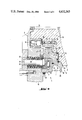
- FIG. 4 is an enlarged view in the region of the run-out groove of a rope drum of the winch of FIGS. 3 and 5;
- FIG. 5 is a horizontal section view taken through the winch of FIG. 1.
- the winch of FIG. 1 includes a frame housing 2 wherein two rope drums 3, 4 are rotatably journalled and are arranged so as to be mutually parallel and in spaced relationship to each other.
- the two rope drums 3, 4 are driven via a motor M which is preferably configured as an oil motor.
- a branching gear transmission G is mounted after the drive motor.
- the transmission G is preferably configured as a gear wheel transmission for a mecnanically rigid drive connection and both rope drums 3, 4 are moved with the same rotational speed.
- the rope drums 3, 4 have peripheral grooves 5 in which the rope 6 is guided.
- a load L (not shown) is attachable to the rope 6 which is slung around both rope drums 3, 4.
- the rope 6 first runs in on the rope drum 3.
- the rope 6 leaves the rope drum 3 at the other side in the region of a run-out groove 7.
- the run-out groove 7 is configured on the periphery of a drive disc 8 which is configured to be separate from the rope drum 3 and is, however, journalled thereon.
- the run-out groove 7 is bounded by a tightening disc 9 which is pressable against the side of the rope 6.
- the rope 6 can, for example, become intensely dirtied with mud or the like.
- the dirt is deposited in the peripheral grooves 5 when pulling in the rope 6, a change of the diameter of the rope drum occurs.
- a dirt layer 10 builds up in the peripheral grooves 5, different peripheral velocities then occur as a consequence thereof on the rope drums 3, 4 in the region where the rope 6 is slung about the drums, the rope drums 3, 4 being driven at the same rotational speed.
- Such a slip clutch can be mounted on either rope drum 3 or rope drum 4 or also on both rope drums 3, 4 and is preferably configured as a laminar coupling.
- a free-runner 11 is provided pursuant to the invention on which the drive disc 8 is journalled.
- the free runner 11 is located on an axial projection 12 of the rope drum 3 and is so configured that an operative connection for an unloaded rope 6 is immediately discontinued, the operative connection existing when the rope 6 is run out under load.
- the drive disc 8 comes to an immediate standstill when the rope 6 is unloaded since sufficient friction is no longer provided via the free runner 11 for driving the rope drum 3. Only when an adequate tension force acts on rope 6, is the frictive engagement on the free runner 11 so large that the drive disc 8 rotates therewith to run out the rope 6.
- FIG. 4 shows that the axial projection 12 with the free runner 11 disposed thereon and the drive disc 8 mounted on the free runner 11 is arranged in the region between an axial bearing support 13 and an end wall 14 of the rope drum 3.
- a self-aligning bearing 15 is mounted on the bearing support 13 by means of which the rope drum 3 is journalled in a housing wall 16.
- the free runner 11 has a bearing 17 mounted on each side thereof and is located with these bearings 17 in an annular gap 18 located between the axial projection 12 and the drive disc 8.
- the annular gap 18 is bounded on the side facing toward end wall 14 by a spacer ring 19.
- a disc 20 is located on the side of the annular gap 18 opposite to self-aligning bearing 15.
- a bearing 22 is mounted and is configured as a needle thrust bearing.
- two radial sealing rings 23, 24 are provided of which one radial sealing ring 23 is journalled under the bearing 22 also between the end wall 14 of the drum 3 and the end face 21 of the drive disc 8 whereas, the other radial sealing ring 24 is located on the opposite side between the drive disc 8 and the housing wall 16.
- a sealing ring 26 is journalled above the bearing 22 in a separation gap 25 near the peripheral groove 5 between the end wall 14 and the end face 21 so that the bearing 22 is shielded from the outside against dirt.
- the axially displaceable tightening disc 9 is journalled on a collar 27 formed on the drive disc 8.
- a further sealing ring 28 is provided on the outside between the tightening disc 9 and the housing wall 16.
- the tightening disc 9 is pressed in a direction against the rope 6 by means of the force of a spring-loaded biasing unit 29.
- the spring-loaded biasing unit 29 includes multi-layered saucer springs 30 through which a pin 31 passes.
- the pin 31 is journalled in an annular disc 32 which is fixedly attached outside on the housing wall 16.
- the pin 31 presses against a pressure disc 33 which, in turn, acts against the needle bearing 34 which is journalled in a recess of the tightening disc 9 between the latter and the pressure disc 33.
- the pressure disc 8 includes a peripheral projection 35 which has a concave lateral surface 36 defining a portion of the run-out groove 7.
- the tightening disc 9 has a likewise concave surface portion 37 which defines a portion of the run-out groove 7.
- the peripheral projection 35 On the side lying opposite the lateral surface 36, the peripheral projection 35 has a concave surface 38 which defines in part the peripheral groove 5 of the rope drum 3 disposed next to the run-out groove 7.
- the separately configured drive disc 8 and the interposition of the free runner 11 assure that the rope 6 will form no loops when pulled out also when it is dirty; instead, it will atuomatically come to a standstill if no tension force is applied forward on the rope 6 during pull-out.
- the drive disc and free runner configuration according to the invention provide a substantially simpler solution with respect to known measures which is substantially free of maintenance and failure. It is understood that the foregoing description is that of the preferred embodiments of the invention and that various changes and modifications may be made thereto without departing from the spirit and scope of the invention as defined in the appended claims.
Landscapes
- Engineering & Computer Science (AREA)
- Mechanical Engineering (AREA)
- Pulleys (AREA)
- Gear Transmission (AREA)
- Manufacture Of Motors, Generators (AREA)
- Windings For Motors And Generators (AREA)
- Transmission Devices (AREA)
- Devices For Conveying Motion By Means Of Endless Flexible Members (AREA)
Applications Claiming Priority (2)
| Application Number | Priority Date | Filing Date | Title |
|---|---|---|---|
| DE19843428875 DE3428875A1 (de) | 1984-08-04 | 1984-08-04 | Durchlaufwinde |
| DE3428875 | 1984-08-04 |
Publications (1)
| Publication Number | Publication Date |
|---|---|
| US4632363A true US4632363A (en) | 1986-12-30 |
Family
ID=6242415
Family Applications (1)
| Application Number | Title | Priority Date | Filing Date |
|---|---|---|---|
| US06/762,107 Expired - Lifetime US4632363A (en) | 1984-08-04 | 1985-08-02 | Winch having a drive disc connectable to a rope drum in dependence upon the load applied to the rope |
Country Status (9)
| Country | Link |
|---|---|
| US (1) | US4632363A (fr) |
| JP (1) | JPS6145893A (fr) |
| CA (1) | CA1254877A (fr) |
| CH (1) | CH667074A5 (fr) |
| DE (1) | DE3428875A1 (fr) |
| FR (1) | FR2568558B1 (fr) |
| GB (1) | GB2164621B (fr) |
| IT (1) | IT1215297B (fr) |
| SE (1) | SE8503659L (fr) |
Cited By (2)
| Publication number | Priority date | Publication date | Assignee | Title |
|---|---|---|---|---|
| US5314166A (en) * | 1991-10-07 | 1994-05-24 | Muir Engineering Pty. Limited | Self-tailing winch with free-fall capacity |
| US20230135307A1 (en) * | 2021-10-29 | 2023-05-04 | Hall Labs Llc | Winch |
Families Citing this family (1)
| Publication number | Priority date | Publication date | Assignee | Title |
|---|---|---|---|---|
| NL1012187C1 (nl) * | 1999-05-31 | 2000-12-01 | Leppink Kampen Beheer | Hijswerktuig. |
Citations (8)
| Publication number | Priority date | Publication date | Assignee | Title |
|---|---|---|---|---|
| US3120043A (en) * | 1962-06-01 | 1964-02-04 | Henley J Carl | Self locking cleat |
| GB1335659A (en) * | 1969-11-21 | 1973-10-31 | W C Coombs | Winch |
| US3776519A (en) * | 1972-01-11 | 1973-12-04 | Fairey Winches Ltd | Cable handling apparatus |
| US3887164A (en) * | 1969-11-21 | 1975-06-03 | William Charles Coombs | Winch |
| US3968953A (en) * | 1975-01-27 | 1976-07-13 | Barient Company | Self-tailing winch |
| DE2517796A1 (de) * | 1975-04-22 | 1976-11-04 | Rotzler Ohg | Durchlaufwinde |
| US4193311A (en) * | 1975-05-17 | 1980-03-18 | Greifzug Gesellschaft Fur Hebezeugbau M.B.H. | Driving pulley mechanism |
| US4225119A (en) * | 1977-09-01 | 1980-09-30 | Rotzler Gmbh & Co. Spezialfabrik Fur Seilwinden Und Hebezeuge | Continuous winch |
Family Cites Families (12)
| Publication number | Priority date | Publication date | Assignee | Title |
|---|---|---|---|---|
| FR1105165A (fr) * | 1952-10-17 | 1955-11-28 | Entpr S Soc Gen | Perfectionnements aux treuils |
| DE1221413B (de) * | 1961-10-25 | 1966-07-21 | Nautec Corp | Seilwinde mit zwei Treibscheiben und einer Speichertrommel |
| FR1381295A (fr) * | 1963-07-31 | 1964-12-14 | Entpr S Soc Gen | Treuil pour le déroulage de câbles |
| GB1148995A (en) * | 1967-10-25 | 1969-04-16 | Theodore J Koenig | Cable Winch Assembly |
| GB1238290A (fr) * | 1967-11-14 | 1971-07-07 | ||
| GB1305899A (fr) * | 1969-03-11 | 1973-02-07 | ||
| US3966170A (en) * | 1971-05-19 | 1976-06-29 | Ocean Systems, Inc. | Traction winch |
| GB1345124A (en) * | 1972-03-17 | 1974-01-30 | Schat Davits Ltd | Winch mechanism for lowring a lifeboat launach or the like suspended from two falls into the water and hoisting it out of the water |
| US3915433A (en) * | 1974-10-10 | 1975-10-28 | Caterpillar Tractor Co | Disconnect clutch assembly for winch drum |
| CH644083A5 (en) * | 1980-01-18 | 1984-07-13 | Schneider August Co Ag | Capstan winch |
| GB2127917B (en) * | 1982-09-28 | 1986-01-29 | Eric Southam | Two speed reduction gearbox |
| DE3428874A1 (de) * | 1984-08-04 | 1986-02-13 | Rotzler GmbH + Co Spezialfabrik für Seilwinden und Hebezeuge, 7853 Steinen | Durchlaufwinde |
-
1984
- 1984-08-04 DE DE19843428875 patent/DE3428875A1/de not_active Withdrawn
-
1985
- 1985-07-23 CH CH3194/85A patent/CH667074A5/de not_active IP Right Cessation
- 1985-07-31 SE SE8503659A patent/SE8503659L/ not_active Application Discontinuation
- 1985-08-02 GB GB08519514A patent/GB2164621B/en not_active Expired
- 1985-08-02 IT IT8521861A patent/IT1215297B/it active
- 1985-08-02 FR FR858511904A patent/FR2568558B1/fr not_active Expired
- 1985-08-02 US US06/762,107 patent/US4632363A/en not_active Expired - Lifetime
- 1985-08-02 CA CA000488038A patent/CA1254877A/fr not_active Expired
- 1985-08-03 JP JP60170586A patent/JPS6145893A/ja active Pending
Patent Citations (8)
| Publication number | Priority date | Publication date | Assignee | Title |
|---|---|---|---|---|
| US3120043A (en) * | 1962-06-01 | 1964-02-04 | Henley J Carl | Self locking cleat |
| GB1335659A (en) * | 1969-11-21 | 1973-10-31 | W C Coombs | Winch |
| US3887164A (en) * | 1969-11-21 | 1975-06-03 | William Charles Coombs | Winch |
| US3776519A (en) * | 1972-01-11 | 1973-12-04 | Fairey Winches Ltd | Cable handling apparatus |
| US3968953A (en) * | 1975-01-27 | 1976-07-13 | Barient Company | Self-tailing winch |
| DE2517796A1 (de) * | 1975-04-22 | 1976-11-04 | Rotzler Ohg | Durchlaufwinde |
| US4193311A (en) * | 1975-05-17 | 1980-03-18 | Greifzug Gesellschaft Fur Hebezeugbau M.B.H. | Driving pulley mechanism |
| US4225119A (en) * | 1977-09-01 | 1980-09-30 | Rotzler Gmbh & Co. Spezialfabrik Fur Seilwinden Und Hebezeuge | Continuous winch |
Cited By (3)
| Publication number | Priority date | Publication date | Assignee | Title |
|---|---|---|---|---|
| US5314166A (en) * | 1991-10-07 | 1994-05-24 | Muir Engineering Pty. Limited | Self-tailing winch with free-fall capacity |
| US20230135307A1 (en) * | 2021-10-29 | 2023-05-04 | Hall Labs Llc | Winch |
| US12391524B2 (en) * | 2021-10-29 | 2025-08-19 | Hall Logic, Inc. | Winch |
Also Published As
| Publication number | Publication date |
|---|---|
| GB8519514D0 (en) | 1985-09-11 |
| GB2164621B (en) | 1987-09-16 |
| CA1254877A (fr) | 1989-05-30 |
| IT8521861A0 (it) | 1985-08-02 |
| DE3428875A1 (de) | 1986-02-13 |
| JPS6145893A (ja) | 1986-03-05 |
| FR2568558A1 (fr) | 1986-02-07 |
| SE8503659L (sv) | 1986-02-05 |
| SE8503659D0 (sv) | 1985-07-31 |
| FR2568558B1 (fr) | 1989-03-03 |
| IT1215297B (it) | 1990-01-31 |
| GB2164621A (en) | 1986-03-26 |
| CH667074A5 (de) | 1988-09-15 |
Similar Documents
| Publication | Publication Date | Title |
|---|---|---|
| CA1100059A (fr) | Desserrage manuel d'un frein | |
| US4078770A (en) | Winch with free-wheeling drum | |
| US4142619A (en) | Dump valve for wet clutch | |
| EP0850797A1 (fr) | Unité pour prise de force avec freinage engagé au choix | |
| US3889785A (en) | Disc brake unit | |
| US5299780A (en) | Rope traction device | |
| GB2164620A (en) | Winch | |
| US4903806A (en) | Hydraulically actuated release mechanism for a clutch | |
| US4632363A (en) | Winch having a drive disc connectable to a rope drum in dependence upon the load applied to the rope | |
| EP0107329B1 (fr) | Unité d'embrayage de démarrage à commande hydraulique | |
| US4265341A (en) | Easy-to-assemble sliding arrangement in disc brake | |
| US3853303A (en) | Winch brake assembly | |
| KR100508017B1 (ko) | 음각 인쇄기의 와이핑 실린더 드라이브 | |
| US4463933A (en) | Clutch/brake mechanism | |
| US4650162A (en) | Winch having a compact housing | |
| JPH08219296A (ja) | 滑りリング型シール装置 | |
| JPH01236189A (ja) | エレベータ巻上機 | |
| US3071222A (en) | Winch | |
| US3042169A (en) | Transmission | |
| JPS6212120Y2 (fr) | ||
| JPH0125790Y2 (fr) | ||
| JPH0523858Y2 (fr) | ||
| KR100543018B1 (ko) | 윈치 | |
| CN218207452U (zh) | 一种新型卷筒式联轴器 | |
| KR940008074Y1 (ko) | 클러치와 브레이크가 겸비된 프레스 |
Legal Events
| Date | Code | Title | Description |
|---|---|---|---|
| AS | Assignment |
Owner name: ROTZLER GMBH & CO.. SPEZIALFABRIK FUR SEILWINDEN U Free format text: ASSIGNMENT OF ASSIGNORS INTEREST.;ASSIGNOR:FROMMHERZ, EGON;REEL/FRAME:004468/0164 Effective date: 19850925 |
|
| STCF | Information on status: patent grant |
Free format text: PATENTED CASE |
|
| CC | Certificate of correction | ||
| FEPP | Fee payment procedure |
Free format text: PAT HOLDER CLAIMS SMALL ENTITY STATUS - SMALL BUSINESS (ORIGINAL EVENT CODE: SM02); ENTITY STATUS OF PATENT OWNER: SMALL ENTITY |
|
| FPAY | Fee payment |
Year of fee payment: 4 |
|
| FPAY | Fee payment |
Year of fee payment: 8 |
|
| FPAY | Fee payment |
Year of fee payment: 12 |