US4637027A - Laser light source device - Google Patents
Laser light source device Download PDFInfo
- Publication number
- US4637027A US4637027A US06/654,628 US65462884A US4637027A US 4637027 A US4637027 A US 4637027A US 65462884 A US65462884 A US 65462884A US 4637027 A US4637027 A US 4637027A
- Authority
- US
- United States
- Prior art keywords
- laser
- light source
- source device
- laser light
- faraday rotator
- Prior art date
- Legal status (The legal status is an assumption and is not a legal conclusion. Google has not performed a legal analysis and makes no representation as to the accuracy of the status listed.)
- Expired - Fee Related
Links
Images


Classifications
-
- H—ELECTRICITY
- H01—ELECTRIC ELEMENTS
- H01S—DEVICES USING THE PROCESS OF LIGHT AMPLIFICATION BY STIMULATED EMISSION OF RADIATION [LASER] TO AMPLIFY OR GENERATE LIGHT; DEVICES USING STIMULATED EMISSION OF ELECTROMAGNETIC RADIATION IN WAVE RANGES OTHER THAN OPTICAL
- H01S3/00—Lasers, i.e. devices using stimulated emission of electromagnetic radiation in the infrared, visible or ultraviolet wave range
- H01S3/10—Controlling the intensity, frequency, phase, polarisation or direction of the emitted radiation, e.g. switching, gating, modulating or demodulating
-
- G—PHYSICS
- G01—MEASURING; TESTING
- G01R—MEASURING ELECTRIC VARIABLES; MEASURING MAGNETIC VARIABLES
- G01R33/00—Arrangements or instruments for measuring magnetic variables
- G01R33/02—Measuring direction or magnitude of magnetic fields or magnetic flux
- G01R33/032—Measuring direction or magnitude of magnetic fields or magnetic flux using magneto-optic devices, e.g. Faraday or Cotton-Mouton effect
- G01R33/0322—Measuring direction or magnitude of magnetic fields or magnetic flux using magneto-optic devices, e.g. Faraday or Cotton-Mouton effect using the Faraday or Voigt effect
-
- H—ELECTRICITY
- H01—ELECTRIC ELEMENTS
- H01S—DEVICES USING THE PROCESS OF LIGHT AMPLIFICATION BY STIMULATED EMISSION OF RADIATION [LASER] TO AMPLIFY OR GENERATE LIGHT; DEVICES USING STIMULATED EMISSION OF ELECTROMAGNETIC RADIATION IN WAVE RANGES OTHER THAN OPTICAL
- H01S3/00—Lasers, i.e. devices using stimulated emission of electromagnetic radiation in the infrared, visible or ultraviolet wave range
- H01S3/10—Controlling the intensity, frequency, phase, polarisation or direction of the emitted radiation, e.g. switching, gating, modulating or demodulating
- H01S3/106—Controlling the intensity, frequency, phase, polarisation or direction of the emitted radiation, e.g. switching, gating, modulating or demodulating by controlling devices placed within the cavity
- H01S3/1066—Controlling the intensity, frequency, phase, polarisation or direction of the emitted radiation, e.g. switching, gating, modulating or demodulating by controlling devices placed within the cavity using a magneto-optical device
-
- H—ELECTRICITY
- H01—ELECTRIC ELEMENTS
- H01S—DEVICES USING THE PROCESS OF LIGHT AMPLIFICATION BY STIMULATED EMISSION OF RADIATION [LASER] TO AMPLIFY OR GENERATE LIGHT; DEVICES USING STIMULATED EMISSION OF ELECTROMAGNETIC RADIATION IN WAVE RANGES OTHER THAN OPTICAL
- H01S5/00—Semiconductor lasers
- H01S5/10—Construction or shape of the optical resonator, e.g. extended or external cavity, coupled cavities, bent-guide, varying width, thickness or composition of the active region
- H01S5/14—External cavity lasers
Definitions
- the present invention relates to a light frequency controller wherein two lights having a stabilized frequency difference are generated using a single frequency light source, more particularly, it relates to a light source device preferable for use when a heterodyne measurement is carried out using light.
- the frequency of the light is high, i.e., more than 10 14 Hz, and thus a direct conversion to an electric signal is impossible.
- the light to be measured suffers from interference from another light having a slightly different frequency from the light to be measured, causing a beat signal to be generated.
- the heterodyne measurement method is performed by detecting the phase or the frequency of the beat signal.
- the magnitude of the difference of the two frequencies must be within the range of approximately 10 7 to 10 10 Hz (1/10 4 to 1/10 8 of the frequency of the light to be measured), in which range processing by an electrical circuit becomes possible, the frequencies of the two lights, respectively, are stable and the frequency difference between them is also stable.
- the two lights having the above-mentioned difference of frequencies cannot be obtained from two independent laser light sources, because of their frequency stability. Therefore, when using a single laser light source, the methods of generating two lights having a constant difference of frequencies, for example, by utilizing the Zeeman effect or by utilizing a diffraction effect due to ultrasonic waves, are proposed.
- the ultrasonic wave modulator requires a very strong driving power to obtain a desirable difference of frequencies through a change in the Bragg reflecting condition obtained with ultrasonic waves, and countermeasures are required against the heat generated.
- a method is proposed in which a light I (frequency ⁇ ) from one light source is separated into two lights, and the respective lights are modulated by external signals (frequency ⁇ ) having a phase deviated by 1/4 period using photoelectric elements 1a and 1b.
- the two lights Ia and Ib obtained by the above-mentioned procedure which include the frequencies ⁇ + ⁇ and ⁇ - ⁇ , are further separated into two lights. After an appropriate light path difference between the separated lights Ia and Ib is obtained, the two lights are then combined, and a further two lights Oa (frequency ⁇ + ⁇ ) and Ob (frequency ⁇ - ⁇ ) are taken out separately.
- the two lights having a desirable difference of frequencies can be obtained by a comparatively small external signal (electric or magnetic signal). Also, the two lights having the difference of frequencies are obtained without a magnetic field, a semiconductor laser can be used as a light source, and the problems in the conventional method are effectively solved.
- the intensity thereof is effected by amplitude modulation. As a result, the modulated light is superimposed on the beat signal, and subsequently, separation of the superimposed light becomes difficult.
- the above problems in the conventional methods give rise to disadvantages in that the field of application of these methods is limited.
- the object of the present invention is to provide a laser light source device capable of generating, from a single light source, two lights each having different frequencies, wherein a strong magnetic field or electric field is not necessary, a semiconductor laser can be used as a light source if required, lights having a constant intensity can be easily generated, the dimension of the device is small, the performance of the device is high, and whereby the heterodyne measurement of light can be used over a wider range of applications.
- a laser light source device having a laser and an external resonator, comprising a Faraday rotator at the laser side front of one of the reflection planes included in the external resonator, a clockwise circular polarization and a counter-clockwise circular polarization each having a different frequency being generated by applying the laser light through the Faraday rotator under a magnetic field.
- a laser light source device wherein, when a laser is provided with a resonator in which the eigen-mode is two linear polarizations having oscillational directions crossing each other perpendicularly, elements through which light is emitted and returned in such a manner that the polarization plane is rotated by 90 degrees, are arranged one by one at the laser side front of another reflection plane of the resonator and at the laser side front of the Faraday rotator.
- a laser light source device wherein, when a semiconductor laser is used as a laser light source, the semiconductor laser is provided with an external resonator and elements through which light is emitted and returned in such a manner that the polarlization plane is rotated by 90 degrees, are arranged at an angle of 45 degrees between the axis of the elements and the plane of the active layer in the semiconductor laser.
- FIG. 1 shows a schematic diagram of an example of a conventional light source device for generating, from a single light source, two lights having different frequencies;
- FIG. 2 shows a schematic diagram explaining a fundamental principle of the present invention
- FIG. 3 is a diagram showing a constitution of a laser light source device using a semiconductor laser according to an embodiment of the present invention
- FIG. 4 is a perspective view explaining the semiconductor laser in the device of FIG. 3;
- FIG. 5 is a schematic diagram showing an example of a practical constitution of the laser light source device of FIG. 3.
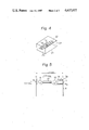
- FIGS. 6 and 7 show plan views of the constitutions of the laser diodes used as modifications in the embodiment of the present invention.
- FIG. 2 is a diagram explaining an operational principle of portions of the fundamental constitution.
- a laser 2 has an external resonator including reflection planes (reflection mirrors) 3 and 4, and a Faraday rotator 5 is provided at the laser 2 side front of one of the reflection planes (reflection plane 4 in the figure).
- the apparent distance between the reflection planes 3 and 4 for the respective polarizations becomes different. Namely, the oscillation frequencies in the clockwise and the counter-clockwise polarizations is different.
- the clockwise and the counter-clockwise circular polarizations are in a time reversal relationship with each other. Namely, at that frequency, they are in a degenerate state. At this time, the magnetic field is applied and the degenerate state is released, and one frequency becomes two frequencies.
- the lights each having different frequencies ⁇ + ⁇ and ⁇ - ⁇ are output through the reflection plane 4.
- the polarizations can be separated and be taken out by passing them through a quarter-wave plate and a polarization separating element not shown). By the same processing, the above two lights can be taken out from the reflection plane 3.
- any arbitrary laser including lights having a circular polarization mode as an oscillatory light can also be used.
- the TE-wave and the TM-wave In the usual semiconductor laser, two linear polarizations crossing each other perpendicularly are called the TE-wave and the TM-wave, and are an eigen-mode of the resonator.
- the polarization plane of the TE-wave In a semiconductor laser 21 as shown in FIG. 4, the polarization plane of the TE-wave is in parallel with and the TM-wave is perpendicular to an active layer 22 plane (hatched plane) which is the light emitting and waveguide domain.
- active layer 22 plane hatchched plane
- the TM-wave irradiated from the end plane 23 of the semiconductor laser 21 is given a circular polarization by the quarter-wave plate 6.
- This circular polarization is reflected by the reflection plane 3, and then is passed back through the quarter-wave plate 6, to again become a linear polarization.
- the wave was a TE-wave.
- the light is irradiated from the end plane 24 and passes through the quarter-wave plate 7, and is then again given a circular polarization.
- This circular polarization is reflected by the reflection plane 4, is passed back through the quarter-wave plate 7, and is then returned as the TM-wave by the rotation of the polarization plane by ⁇ /2.
- the TE-wave irradiated from the end plane 23 of the semiconductor laser 21 is given a circular polarization in a reverse direction to that of the above case through the quarter-wave plate 6, and after the TE-wave is reflected by the reflection plane 3, the TE-wave is converted to the TM-wave through the quarter-wave plate 6. Further, the wave is irradiated from the end plane 24, is given a circular polarization in the reverse direction through the quarter-wave plate 7, is reflected by the reflection plane 4, and is then passed through the quarter-wave plate 7 and returned as the TE-wave.
- the decision of whether the clockwise or the counter-clockwise circular polarization is given to the respective TE-wave and TM-wave is determined by the positive or negative sign of the angle of ⁇ 45 degree which is formed by the axis of the quarter-wave plate and the active layer plane.
- the oscillation light of the semiconductor laser 21 resonates in the degenerate state of the TE-wave and TM-wave between the reflection planes 3 and 4.
- the quarter-wave plates 6 and 7 are provided at both sides of the semiconductor laser 21, it is impossible to distinguish between the TE-mode and TM-mode.
- the semiconductor laser can be used as a light source in a manner equivalent to that of a gas laser.
- this semiconductor laser does not need a reflection coating at the end planes 23 and 24, as do the usual semiconductor lasers, it is better to apply the coating to prevent reflection.
- the Faraday rotator 5 for example, comprises a magnetic thin plate 5a made of yttrium-iron-garnet (YIG), performs with the characteristic Faraday effect, and is light transmissible, and a ring magnet 5b for magnetizing the magnetic thin plate 5a along the light transmitting direction ⁇ 1 or ⁇ 2 .
- the magnetic thin plate 5a is mounted in the ring of the ring magnet 5b.
- the construction of the light source device can be made smaller and the control for the frequency difference made easier.
- the advantage is gained of obtaining two lights having a constant intensity.
- a permanent magnet can be used to supply the magnetic field. If an alternating magnetic field is applied, the frequency difference ⁇ can be modulated.
- FIG. 5 shows an example of a practical constitution of a laser light source device according to the embodiment of the present invention.
- a semiconductor laser is used as a light source.
- the semiconductor laser 21 is put on a heat sink 8, and, for example, spherical condenser lenses 9 and 10 are provided at both the light output ends of the semiconductor laser 21.
- Quarter-wave plates 61 and 71 are provided at both sides of the spherical lenses 9 and 10, respectively.
- One side of the quarter-wave plate 61 is coated with a reflection coating 31 having, for example, a reflectivity of 99 percent
- the Faraday rotator 5 is provided adjacent to one side of the quarter-wave plate 71.
- One side of the Faraday rotator 5 is coated with a reflection coating 41 having, for example, a reflectivity of 90 percent.
- the distance between the reflection coatings 31 and 41 is approximately 1 mm, the length between the end planes of the semiconductor laser 21 is approximately 0.3 mm, and the diameter of the spherical lenses 9 and 10 is approximately 0.2 mm.
- the quarter-wave plate is usually made of a quartz plate having double refraction characteristics.
- Each element (2, 3, 4, 5, 6, 7) shown in FIGS. 2 and 3, is practically arranged on stems (not shown) made of non-magnetic metal, e.g., a stainless steel, using a holder for fixing, and a cap (not shown) made of non-magnetic metal is attached to the stems to cover the elements, thus completing the casing of the elements.
- stems not shown
- non-magnetic metal e.g., a stainless steel
- FIGS. 6 and 7 show modifications of the present embodiment.
- the sectional area of the waveguide layer provided adjacent to the active layer of the semiconductor laser 21 is enlarged near the end planes 23 and 24 of the semiconductor laser 21 for receiving and sending the light. These areas are shown as reference numerals 13 and 14 in the plan views of FIG. 6 and FIG. 7, respectively.
- These modifications prevent the reflection of the laser light at the end planes, and thus an external resonator type semiconductor laser light source device, wherein the complex mode rarely occurs and stable oscillation is performed, is obtained.
- the quarter-wave plates 6 and 7 used as the elements in the device of FIG. 3 can be replaced by a 45 degree Faraday rotator made of yttrium-iron-garnet (YIG), through which the polarization plane is rotated by 90 degrees for each light emission and return. Since the quarter-wave plate has double refraction characteristics, integration of the device is difficult. However, if the Faraday rotator is used instead of the quarter-wave plate, integration of the device can be accomplished.
- YIG yttrium-iron-garnet
- the sectional form of the waveguide layer of the semiconductor laser may have anisotropic characteristics. Namely, if the refractive index of the TE-wave is made to be different from that of the TM-wave, the interaction of the two waves becomes weaker, and thus a stable oscillation can be obtained.
- the Faraday rotator 5 having a polarization angle regarding the frequency ⁇ in the present embodiment can be made of a paramagnetic glass.
- the method of heterodyne measurement on light can be applied over a wide field. For example, if a magnetic field to be measured is applied to the Faraday rotator 5, the device operates as a light frequency modulator, and by utilizing the modulated data, a heterodyne type magnetic field measuring device is obtained.
Landscapes
- Physics & Mathematics (AREA)
- Electromagnetism (AREA)
- Engineering & Computer Science (AREA)
- Optics & Photonics (AREA)
- Condensed Matter Physics & Semiconductors (AREA)
- General Physics & Mathematics (AREA)
- Power Engineering (AREA)
- Plasma & Fusion (AREA)
- Semiconductor Lasers (AREA)
- Lasers (AREA)
Applications Claiming Priority (4)
| Application Number | Priority Date | Filing Date | Title |
|---|---|---|---|
| JP17722783A JPH0249667B2 (ja) | 1983-09-26 | 1983-09-26 | Jikikogakusochi |
| JP58-177227 | 1983-09-26 | ||
| JP17723383A JPS6068684A (ja) | 1983-09-26 | 1983-09-26 | レ−ザ光源装置 |
| JP58-177233 | 1983-09-26 |
Publications (1)
| Publication Number | Publication Date |
|---|---|
| US4637027A true US4637027A (en) | 1987-01-13 |
Family
ID=26497847
Family Applications (1)
| Application Number | Title | Priority Date | Filing Date |
|---|---|---|---|
| US06/654,628 Expired - Fee Related US4637027A (en) | 1983-09-26 | 1984-09-26 | Laser light source device |
Country Status (5)
| Country | Link |
|---|---|
| US (1) | US4637027A (fr) |
| EP (1) | EP0138452B1 (fr) |
| KR (1) | KR890003390B1 (fr) |
| CA (1) | CA1251846A (fr) |
| DE (1) | DE3483766D1 (fr) |
Cited By (22)
| Publication number | Priority date | Publication date | Assignee | Title |
|---|---|---|---|---|
| US4794605A (en) * | 1986-03-13 | 1988-12-27 | Trw Inc. | Method and apparatus for control of phase conjugation cells |
| US4941738A (en) * | 1988-07-29 | 1990-07-17 | American Telephone And Telegraph Company | Polarization independent optical amplifier apparatus |
| US4955006A (en) * | 1988-01-13 | 1990-09-04 | Fujitsu Limited | Floating type magneto-optic disk reading head system having external semiconductor laser resonator operating at orthogonal two mode oscillations |
| US4975918A (en) * | 1989-06-07 | 1990-12-04 | Maxwell Laboratories, Inc. | Tunable laser |
| US5007060A (en) * | 1989-08-01 | 1991-04-09 | Litton Systems, Inc. | Linear laser with two-swept frequencies of controlled splitting |
| US5015070A (en) * | 1989-03-14 | 1991-05-14 | Mouse Systems Corporation | Reference grid for optical scanner |
| US5022034A (en) * | 1989-06-27 | 1991-06-04 | May A D | Laser device, including control of polarization mode |
| US5091912A (en) * | 1990-02-13 | 1992-02-25 | Societe D'applications Generales D'electricite Et De Mecanique Sagem | Laser having two modes at different frequencies |
| US5132978A (en) * | 1988-03-02 | 1992-07-21 | British Telecommunications Public Limited Company | Laser amplifier |
| WO1993026066A1 (fr) * | 1992-06-15 | 1993-12-23 | Cygnus Laser Corporation | Convertisseur de frequence optique non lineaire |
| US5355381A (en) * | 1992-12-03 | 1994-10-11 | Amoco Corporation | Self-heterodyne optical fiber communications system |
| US5465154A (en) * | 1989-05-05 | 1995-11-07 | Levy; Karl B. | Optical monitoring of growth and etch rate of materials |
| US5812304A (en) * | 1995-08-29 | 1998-09-22 | Fujitsu Limited | Faraday rotator which generates a uniform magnetic field in a magnetic optical element |
| US5844710A (en) * | 1996-09-18 | 1998-12-01 | Fujitsu Limited | Faraday rotator and optical device employing the same |
| US5867300A (en) * | 1996-03-01 | 1999-02-02 | Fujitsu Limited | Variable optical attenuator which applies a magnetic field to a faraday element to rotate the polarization of a light signal |
| US5889609A (en) * | 1992-07-31 | 1999-03-30 | Fujitsu Limited | Optical attenuator |
| US6018411A (en) * | 1996-11-29 | 2000-01-25 | Fujitsu Limited | Optical device utilizing magneto-optical effect |
| US6212209B1 (en) * | 1998-03-16 | 2001-04-03 | Lucent Technologies, Inc. | Switchable laser using a faraday rotator |
| US6441955B1 (en) | 1998-02-27 | 2002-08-27 | Fujitsu Limited | Light wavelength-multiplexing systems |
| US20020154672A1 (en) * | 1999-09-15 | 2002-10-24 | Yeda Research And Development Co. Ltd. | Optical resonators with orthogonally polarized modes |
| US6496300B2 (en) | 1998-02-27 | 2002-12-17 | Fujitsu Limited | Optical amplifier |
| US6813286B1 (en) | 1997-05-01 | 2004-11-02 | Yeda Research And Development Co. Ltd. | Optical resonators with discontinuous phase elements |
Families Citing this family (6)
| Publication number | Priority date | Publication date | Assignee | Title |
|---|---|---|---|---|
| EP0312296A3 (fr) * | 1987-10-16 | 1990-04-11 | Board Of Regents, The University Of Texas System | Dispositif et procédé pour les mesurages "quanta-non-destruction" au moyen d'oscillation paramétrique |
| US4944592A (en) * | 1987-10-16 | 1990-07-31 | The University Of Texas System | Device and method for quantum nondemolition measurements using parametric oscillation |
| FR2682769B1 (fr) * | 1991-10-17 | 1995-08-11 | Sagem | Magnetometre laser. |
| JP3167189B2 (ja) * | 1992-08-31 | 2001-05-21 | 浜松ホトニクス株式会社 | 電圧測定装置 |
| FR2915631B1 (fr) * | 2007-04-27 | 2009-07-10 | Thales Sa | Source laser compacte a faible largeur spectrale. |
| KR100815483B1 (ko) * | 2007-05-09 | 2008-03-20 | 한국전기연구원 | 비등방성 레이저 결정을 이용한 다이오드 펌핑된 레이저장치 |
Citations (5)
| Publication number | Priority date | Publication date | Assignee | Title |
|---|---|---|---|---|
| US3356438A (en) * | 1963-06-12 | 1967-12-05 | Sperry Rand Corp | Light modulator employing multiplereflective light path |
| US3436677A (en) * | 1964-06-29 | 1969-04-01 | Ibm | Magneto-optic radiation control and modulator |
| US3639855A (en) * | 1969-12-19 | 1972-02-01 | Bell Telephone Labor Inc | Laser devices |
| US4305046A (en) * | 1978-07-12 | 1981-12-08 | Agence Nationale De La Valorisation De La Recherche (Anvar) | Selective optical resonator |
| US4496518A (en) * | 1980-02-27 | 1985-01-29 | Marie G R P | TMO and TEO cavity resonator for projecting plasma confining TEO mode components |
Family Cites Families (1)
| Publication number | Priority date | Publication date | Assignee | Title |
|---|---|---|---|---|
| US4222668A (en) * | 1978-02-23 | 1980-09-16 | Rockwell International Corporation | Ferrimagnetic Faraday elements for ring lasers |
-
1984
- 1984-09-17 CA CA000463409A patent/CA1251846A/fr not_active Expired
- 1984-09-26 DE DE8484306546T patent/DE3483766D1/de not_active Expired - Lifetime
- 1984-09-26 EP EP84306546A patent/EP0138452B1/fr not_active Expired
- 1984-09-26 US US06/654,628 patent/US4637027A/en not_active Expired - Fee Related
- 1984-09-26 KR KR8405900A patent/KR890003390B1/ko not_active Expired
Patent Citations (5)
| Publication number | Priority date | Publication date | Assignee | Title |
|---|---|---|---|---|
| US3356438A (en) * | 1963-06-12 | 1967-12-05 | Sperry Rand Corp | Light modulator employing multiplereflective light path |
| US3436677A (en) * | 1964-06-29 | 1969-04-01 | Ibm | Magneto-optic radiation control and modulator |
| US3639855A (en) * | 1969-12-19 | 1972-02-01 | Bell Telephone Labor Inc | Laser devices |
| US4305046A (en) * | 1978-07-12 | 1981-12-08 | Agence Nationale De La Valorisation De La Recherche (Anvar) | Selective optical resonator |
| US4496518A (en) * | 1980-02-27 | 1985-01-29 | Marie G R P | TMO and TEO cavity resonator for projecting plasma confining TEO mode components |
Cited By (32)
| Publication number | Priority date | Publication date | Assignee | Title |
|---|---|---|---|---|
| US4794605A (en) * | 1986-03-13 | 1988-12-27 | Trw Inc. | Method and apparatus for control of phase conjugation cells |
| US4955006A (en) * | 1988-01-13 | 1990-09-04 | Fujitsu Limited | Floating type magneto-optic disk reading head system having external semiconductor laser resonator operating at orthogonal two mode oscillations |
| US5132978A (en) * | 1988-03-02 | 1992-07-21 | British Telecommunications Public Limited Company | Laser amplifier |
| US4941738A (en) * | 1988-07-29 | 1990-07-17 | American Telephone And Telegraph Company | Polarization independent optical amplifier apparatus |
| US5015070A (en) * | 1989-03-14 | 1991-05-14 | Mouse Systems Corporation | Reference grid for optical scanner |
| US5465154A (en) * | 1989-05-05 | 1995-11-07 | Levy; Karl B. | Optical monitoring of growth and etch rate of materials |
| US4975918A (en) * | 1989-06-07 | 1990-12-04 | Maxwell Laboratories, Inc. | Tunable laser |
| US5022034A (en) * | 1989-06-27 | 1991-06-04 | May A D | Laser device, including control of polarization mode |
| US5007060A (en) * | 1989-08-01 | 1991-04-09 | Litton Systems, Inc. | Linear laser with two-swept frequencies of controlled splitting |
| US5091912A (en) * | 1990-02-13 | 1992-02-25 | Societe D'applications Generales D'electricite Et De Mecanique Sagem | Laser having two modes at different frequencies |
| WO1993026066A1 (fr) * | 1992-06-15 | 1993-12-23 | Cygnus Laser Corporation | Convertisseur de frequence optique non lineaire |
| US6275323B1 (en) | 1992-07-31 | 2001-08-14 | Fujitsu Limited | Optical attenuator |
| US6018412A (en) * | 1992-07-31 | 2000-01-25 | Fujitsu Limited | Optical attenuator |
| US5889609A (en) * | 1992-07-31 | 1999-03-30 | Fujitsu Limited | Optical attenuator |
| US5355381A (en) * | 1992-12-03 | 1994-10-11 | Amoco Corporation | Self-heterodyne optical fiber communications system |
| US5812304A (en) * | 1995-08-29 | 1998-09-22 | Fujitsu Limited | Faraday rotator which generates a uniform magnetic field in a magnetic optical element |
| US5973821A (en) * | 1996-03-01 | 1999-10-26 | Fujitsu Limited | Variable optical attenuator which applies a magnetic field to a faraday element to rotate the polarization of light signal |
| US6570699B2 (en) | 1996-03-01 | 2003-05-27 | Fujitsu Limited | Variable optical attenuator which applies a magnetic field to a Faraday element to rotate the polarization of a light signal |
| US5867300A (en) * | 1996-03-01 | 1999-02-02 | Fujitsu Limited | Variable optical attenuator which applies a magnetic field to a faraday element to rotate the polarization of a light signal |
| US6717713B2 (en) | 1996-03-01 | 2004-04-06 | Fujitsu Limited | Variable optical attenuator which applies a magnetic field to a faraday element to rotate the polarization of a light signal |
| US20030210451A1 (en) * | 1996-03-01 | 2003-11-13 | Fujitsu Limited | Variable optical attenuator which applies a magnetic field to a faraday element to rotate the polarization of a light signal |
| US6333806B1 (en) | 1996-03-01 | 2001-12-25 | Fujitsu Limited | Variable optical attenuator which applies a magnetic field to a Faraday element to rotate the polarization of a light signal |
| US5844710A (en) * | 1996-09-18 | 1998-12-01 | Fujitsu Limited | Faraday rotator and optical device employing the same |
| US6018411A (en) * | 1996-11-29 | 2000-01-25 | Fujitsu Limited | Optical device utilizing magneto-optical effect |
| US6813286B1 (en) | 1997-05-01 | 2004-11-02 | Yeda Research And Development Co. Ltd. | Optical resonators with discontinuous phase elements |
| US6496300B2 (en) | 1998-02-27 | 2002-12-17 | Fujitsu Limited | Optical amplifier |
| US20030025965A1 (en) * | 1998-02-27 | 2003-02-06 | Fujitsu Limited | Light wavelength-multiplexing systems |
| US6441955B1 (en) | 1998-02-27 | 2002-08-27 | Fujitsu Limited | Light wavelength-multiplexing systems |
| US6919987B2 (en) | 1998-02-27 | 2005-07-19 | Fujitsu Limited | Light wavelength-multiplexing systems |
| US6212209B1 (en) * | 1998-03-16 | 2001-04-03 | Lucent Technologies, Inc. | Switchable laser using a faraday rotator |
| US20020154672A1 (en) * | 1999-09-15 | 2002-10-24 | Yeda Research And Development Co. Ltd. | Optical resonators with orthogonally polarized modes |
| US6850544B2 (en) * | 1999-09-15 | 2005-02-01 | Yeda Research And Development Co., Ltd. | Optical resonators with orthogonally polarized modes |
Also Published As
| Publication number | Publication date |
|---|---|
| KR890003390B1 (en) | 1989-09-19 |
| KR850002611A (ko) | 1985-05-15 |
| EP0138452A3 (en) | 1987-04-29 |
| CA1251846A (fr) | 1989-03-28 |
| EP0138452A2 (fr) | 1985-04-24 |
| EP0138452B1 (fr) | 1990-12-19 |
| DE3483766D1 (de) | 1991-01-31 |
Similar Documents
| Publication | Publication Date | Title |
|---|---|---|
| US4637027A (en) | Laser light source device | |
| CA1304970C (fr) | Interferometre a fibre conservant la polarisation et methode de stabilisation des sources | |
| US4890922A (en) | Thermally compensated reference interferometer and method | |
| US4274742A (en) | Passive ring laser rate of turn devices | |
| JPH05129700A (ja) | レーザシステム及び周波数変換方法 | |
| US5617435A (en) | Lasing system with wavelength-conversion waveguide | |
| JPH02119280A (ja) | レーザ共振器 | |
| JP2501302B2 (ja) | レ―ザ―装置および方法 | |
| US7551342B2 (en) | Optical frequency comb generator and optical modulator | |
| KR910006660B1 (ko) | 직교하는 2개의 발진 모우드에서 동작하는 외부 반도체 레이저 공진기를 갖는 부동형 광자기 디스크 리딩헤드 시스템 | |
| JPS63279115A (ja) | レーザおよび環状共振器を有する測定装置 | |
| KR0174775B1 (ko) | 파장변환 도파로형 레이저 장치 | |
| US3418476A (en) | Device for internal modulation of laser radiation | |
| JP3756959B2 (ja) | 光周波数コム発生器 | |
| GB2201256A (en) | Thermally compensated reference interferometer and method | |
| US3752586A (en) | Minimizing frequency locking in ring laser gyroscopes | |
| CN114370928B (zh) | 一种直线型萨格纳克干涉式光纤振动传感器 | |
| JP3428067B2 (ja) | 変位測定方法及びそれに用いる変位測定装置 | |
| US4765740A (en) | Optical apparatus based on measurement of phase or frequency shift of an oscillating beam, particularly useful as an optical gyro | |
| Kravtsov et al. | Nonlinear dynamics of solid-state ring lasers | |
| US3486130A (en) | Ring laser having a quarter wave plate for rotating the plane of polarization of light which is reflected back into the ring from the combining optics | |
| US3500233A (en) | Frequency modulated laser device | |
| Boon-Engering et al. | Stabilization of an optical cavity containing a birefringent element | |
| US3941481A (en) | Ring laser having elastic wave bias | |
| JPH0136986B2 (fr) |
Legal Events
| Date | Code | Title | Description |
|---|---|---|---|
| AS | Assignment |
Owner name: FUJITSU LIMITED, 1015, KAMIKODANAKA, NAKAHARA-KU, Free format text: ASSIGNMENT OF ASSIGNORS INTEREST.;ASSIGNORS:SHIRASAKI, MASATAKA;NAKAJIMA, HIROCHIKA;FURUKAWA, YASUO;AND OTHERS;REEL/FRAME:004318/0958 Effective date: 19840905 |
|
| FEPP | Fee payment procedure |
Free format text: PAYOR NUMBER ASSIGNED (ORIGINAL EVENT CODE: ASPN); ENTITY STATUS OF PATENT OWNER: LARGE ENTITY |
|
| FPAY | Fee payment |
Year of fee payment: 4 |
|
| REMI | Maintenance fee reminder mailed | ||
| LAPS | Lapse for failure to pay maintenance fees | ||
| FP | Lapsed due to failure to pay maintenance fee |
Effective date: 19990113 |
|
| STCH | Information on status: patent discontinuation |
Free format text: PATENT EXPIRED DUE TO NONPAYMENT OF MAINTENANCE FEES UNDER 37 CFR 1.362 |