US4641589A - Process for the rapid assembly of elements composing a structure - Google Patents
Process for the rapid assembly of elements composing a structure Download PDFInfo
- Publication number
- US4641589A US4641589A US06/704,916 US70491685A US4641589A US 4641589 A US4641589 A US 4641589A US 70491685 A US70491685 A US 70491685A US 4641589 A US4641589 A US 4641589A
- Authority
- US
- United States
- Prior art keywords
- elements
- jaw members
- post
- process according
- keystones
- Prior art date
- Legal status (The legal status is an assumption and is not a legal conclusion. Google has not performed a legal analysis and makes no representation as to the accuracy of the status listed.)
- Expired - Fee Related
Links
- 238000000034 method Methods 0.000 title claims abstract description 24
- 239000007787 solid Substances 0.000 description 5
- 238000010276 construction Methods 0.000 description 4
- 239000011521 glass Substances 0.000 description 3
- 239000011819 refractory material Substances 0.000 description 3
- 239000002184 metal Substances 0.000 description 2
- 229910018404 Al2 O3 Inorganic materials 0.000 description 1
- MCMNRKCIXSYSNV-UHFFFAOYSA-N ZrO2 Inorganic materials O=[Zr]=O MCMNRKCIXSYSNV-UHFFFAOYSA-N 0.000 description 1
- 229910052681 coesite Inorganic materials 0.000 description 1
- 229910052906 cristobalite Inorganic materials 0.000 description 1
- 239000003292 glue Substances 0.000 description 1
- 238000012986 modification Methods 0.000 description 1
- 230000004048 modification Effects 0.000 description 1
- 230000000284 resting effect Effects 0.000 description 1
- 230000000717 retained effect Effects 0.000 description 1
- 239000000377 silicon dioxide Substances 0.000 description 1
- VYPSYNLAJGMNEJ-UHFFFAOYSA-N silicon dioxide Inorganic materials O=[Si]=O VYPSYNLAJGMNEJ-UHFFFAOYSA-N 0.000 description 1
- 229910052682 stishovite Inorganic materials 0.000 description 1
- 238000006467 substitution reaction Methods 0.000 description 1
- 229910052905 tridymite Inorganic materials 0.000 description 1
Images


Classifications
-
- E—FIXED CONSTRUCTIONS
- E04—BUILDING
- E04G—SCAFFOLDING; FORMS; SHUTTERING; BUILDING IMPLEMENTS OR AIDS, OR THEIR USE; HANDLING BUILDING MATERIALS ON THE SITE; REPAIRING, BREAKING-UP OR OTHER WORK ON EXISTING BUILDINGS
- E04G21/00—Preparing, conveying, or working-up building materials or building elements in situ; Other devices or measures for constructional work
- E04G21/14—Conveying or assembling building elements
- E04G21/16—Tools or apparatus
-
- E—FIXED CONSTRUCTIONS
- E04—BUILDING
- E04G—SCAFFOLDING; FORMS; SHUTTERING; BUILDING IMPLEMENTS OR AIDS, OR THEIR USE; HANDLING BUILDING MATERIALS ON THE SITE; REPAIRING, BREAKING-UP OR OTHER WORK ON EXISTING BUILDINGS
- E04G21/00—Preparing, conveying, or working-up building materials or building elements in situ; Other devices or measures for constructional work
- E04G21/14—Conveying or assembling building elements
- E04G21/16—Tools or apparatus
- E04G21/18—Adjusting tools; Templates
- E04G21/1841—Means for positioning building parts or elements
-
- E—FIXED CONSTRUCTIONS
- E04—BUILDING
- E04G—SCAFFOLDING; FORMS; SHUTTERING; BUILDING IMPLEMENTS OR AIDS, OR THEIR USE; HANDLING BUILDING MATERIALS ON THE SITE; REPAIRING, BREAKING-UP OR OTHER WORK ON EXISTING BUILDINGS
- E04G21/00—Preparing, conveying, or working-up building materials or building elements in situ; Other devices or measures for constructional work
- E04G21/14—Conveying or assembling building elements
- E04G21/16—Tools or apparatus
- E04G21/18—Adjusting tools; Templates
- E04G21/1841—Means for positioning building parts or elements
- E04G21/1858—Templates for window or door openings, e.g. in a masonry wall
- E04G21/1866—Templates for window or door openings, e.g. in a masonry wall for making arches
-
- F—MECHANICAL ENGINEERING; LIGHTING; HEATING; WEAPONS; BLASTING
- F27—FURNACES; KILNS; OVENS; RETORTS
- F27D—DETAILS OR ACCESSORIES OF FURNACES, KILNS, OVENS OR RETORTS, IN SO FAR AS THEY ARE OF KINDS OCCURRING IN MORE THAN ONE KIND OF FURNACE
- F27D1/00—Casings; Linings; Walls; Roofs
- F27D1/16—Making or repairing linings ; Increasing the durability of linings; Breaking away linings
- F27D1/1621—Making linings by using shaped elements, e.g. bricks
-
- Y—GENERAL TAGGING OF NEW TECHNOLOGICAL DEVELOPMENTS; GENERAL TAGGING OF CROSS-SECTIONAL TECHNOLOGIES SPANNING OVER SEVERAL SECTIONS OF THE IPC; TECHNICAL SUBJECTS COVERED BY FORMER USPC CROSS-REFERENCE ART COLLECTIONS [XRACs] AND DIGESTS
- Y10—TECHNICAL SUBJECTS COVERED BY FORMER USPC
- Y10S—TECHNICAL SUBJECTS COVERED BY FORMER USPC CROSS-REFERENCE ART COLLECTIONS [XRACs] AND DIGESTS
- Y10S52/00—Static structures, e.g. buildings
- Y10S52/01—Hand tools for assembling building components
Definitions
- the invention relates to a process for the rapid assembly of elements composing a structure and to a device for temporarily maintaining such elements in the assembled position, useful in carrying out the said process.
- the process of the invention has been developed for the construction of refractory vaults of regenerator chambers and basins of glass furnaces, but it can also be used for assembling the walls of regenerator chambers or furnaces when the height of the structure presents a problem.
- the process of the invention could also be useful in the sector of civil-engineering construction in general.
- the vaults consist of several arches placed side by side, each arch consisting of keyed refractory elements or blocks (also called keystones) which bear on the vertical walls by means of cushions.
- these vault arches are assembled with the use of a truss which serves as a template and a support for the keystones, the said truss itself resting on a previously erected scaffolding.
- the keystones of a particular arch are installed one after the other, with the use of wedges for adjustment purposes. Only when a vault arch is completely formed and holds firm because of the keying of the keystones is it possible to displace the truss and begin assembling the following arch. This method of construction obviously takes a long time and is consequently costly.
- the subject of the invention is a process for the rapid assembly of at least two elements composing a structure, making it possible to do without the use of a scaffolding.
- the subject of the invention is a process for the rapid assembly of all the elements composing a vault arch, in particular for regenerator chambers or basins of glass furnaces.
- the subject of the invention is a device useful for carrying out the process of the invention, this device making it possible to maintain two adjacent component elements to be fitted, temporarily in their assembled position during the transport of these from the ground up to their final position.
- the invention relates to a process for the rapid assembly of at least two elements composing a structure, this process being defined in that it involves:
- the structure to be built is a vault arch
- stage (a) involves arranging flat and on the ground all the keystones composing the vault arch in the desired vault-arch configuration.
- the elements composing the structure can be solid or hollow elements.
- this device comprises a post, two spaced jaws located opposite one another and carried by said post, at least one of these jaws being moveable, means of clamping the jaws on the elements to be held assembled and, integral with one of the said jaws, members projecting in the direction of the other jaw and designed to engage a recess provided in each element of a pair of adjacent elements to be held assembled.
- the device consists of a fixed part in the general form of a right-angle bracket, one of the branches of the right-angle bracket forming a first jaw and the other branch forming a post, a second moveable jaw located opposite the first jaw and mounted to slide on said other branch of the right-angle bracket, means of clamping the jaws on the elements to be held assembled, and members which are integral with one of the jaws and projecting in the direction of the other jaw and which are designed to engage a recess provided in each of two adjacent elements to be held assembled.
- the invention makes it possible not only to gain a considerably amount of time, but also to achieve a saving in terms of the costly scaffolding and template. Also, the component elements can be assembled on the ground with a precision which is generally higher than in the traditional method of construction.
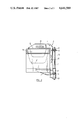
- FIG. 1 is a plan view illustrating the use of the process and device according to the invention for assembling a refractory vault made of hollow keystones;
- FIG. 2 is a side view of the unit in FIG. 1 along the line II--II;
- FIG. 3 is a plan view, similar to that of FIG. 1, illustrating and alternative embodiment suitable for assembling a refractory vault made of solid keystones.
- FIGS. 1 and 2 illustrate how the process and device according to the invention are used to assemble a refractory vault arch.
- FIGS. 1 and 2 show only part of a vault arch which actually consists of n keystones 1 made of refractory material.
- the keystones 1 are hollow at 2 in their upper part over some of their height, in order to make them lighter.
- Such keystones are intended to be filled with an insulating refractory material.
- These keystones can consist, for example, of an electro-fused refractory material of the system Al 2 O 3 -ZrO 2 -SiO 2 and, as an indication, can have the following dimensions (length: 300 mm, height 200 to 250 mm and width 300 mm).
- the recess 2 can extend over more than half the height of the keystone (for example, 140 mm for a height of 250 mm).
- the keystones 1 are arranged flat, side by side, in the relative position which they will occupy in the vault arch to be produced (FIG. 1). Once this has been done, the keystones are joined to one another in pairs by means of assembly devices designated by the reference numeral 3.
- Each device 3 is composed of a fixed part 4 in the general form of a right-angle bracket and consisting of a metal sectional piece with a T-shaped cross-section.
- One of the branches of the right-angle bracket forms a first jaw 5 whilst the other forms a post 6, on which is mounted a second jaw 7 located opposite the first jaw 5.
- the jaw 7 has a forked configuration grooved on the inside at its end located on the same side as the sectional post 6, so that it can be threaded onto the post and slide on it.
- the jaws 5 and 7 are clamped against the elements or keystones to be held together in a very easy way by means of a screw-and-nut system.
- the jaw 7 is fixed, via a yoke 8 articulated about an axle 9, to a threaded rod 10 which passes through a lug 11 which is welded to the post 6 and on the end of which is screwed a nut 12 bearing on the lug 11.
- the screwing of the nut 12 makes it possible to clamp the jaws, as is obvious.
- the axle 9 passes throught a slot 13 provided in the lower part of the post in order to limit the stroke of the jaw 7.
- the device also possesses two inclined wings 14 integral with the jaw 5.
- n-1 devices 3 (only two devices are shown in FIG. 1 for the sake of a simple representation). Each device is put in place, with the nut 12 removed, so that the jaws can be moved apart sufficiently to allow the wings 14 to be introduced into recesses 2 in each pair of adjacent keystones. When this has been done, the screw 10 is, if necessary, rethreaded into the lug 11 and the nut 12 screwed, until the jaws clamp the keystones sufficiently to keep them assembled.
- a hook or a cable connected to a suitable lifting appliance is passed through the notch 15 in the central device 3 (or in two devices 3), so that the assembled vault arch can be brought into its position in the structure being built.
- the lifting operation is preferably carried out in two stages, that is to say the vault arch lying horizontally is first raised into an upright position, and then it is actually lifted.
- the castellated form of the notches makes it possible to select the point of engagement of the hook or cable on the vault arch, so as to present it in the appropriate assembly position on the cushions.
- the assembly devices 3 are dismantled. It is sufficient for this purpose, to unscrew the nuts 12 until the threaded rod 10 is released. The devices 3 can then be removed easily.
- the same devices 3 can serve for maintaining in the assembled position a plurality of hollow refractory blocks of parallelepipedic, rather than keyed form. Such blocks are used to form the upper part of the walls of regenerator chambers. It is often difficult to instal these blocks in the conventional way because of the height at which they are located. The invention can achieve real progress in this respect.
- the lifting means are secured via the notch 16 instead of the notch 15, so that the elements can be put in place without the assembly devices 3 impeding the laying operation.
- the various assembly devices 3 which are used can be fixed to one another by means of a metal bar or the like connecting them to one another, for example in the region of a notch, in order to increase the strenght of the assembly.
- FIG. 3 illustrates an alternative embodiment of the devices 3 which is designed for assembling solid refractory elements, such as keystones 21 composing a vault arch.
- the inclined wings 14 are replaced by two wings 22, each of which is substantially parallel to the upper surface of the keystone over which it extends. These wings are provided with studs 23 which are directed downwards and which engage recesses or impressions 24 of matching shape formed in the upper part of the keystones.
- the assembly devices and their use are as described in relation to FIGS. 1 and 2.
- This alternative embodiment could also serve for assembling solid parallelepipedic refractory blocks, in a way similar to that described with reference to FIGS. 1 and 2.
Landscapes
- Engineering & Computer Science (AREA)
- Architecture (AREA)
- Mechanical Engineering (AREA)
- Civil Engineering (AREA)
- Structural Engineering (AREA)
- General Engineering & Computer Science (AREA)
- Furnace Housings, Linings, Walls, And Ceilings (AREA)
- Conveying And Assembling Of Building Elements In Situ (AREA)
- Joining Of Building Structures In Genera (AREA)
- Furnace Details (AREA)
- Electrical Discharge Machining, Electrochemical Machining, And Combined Machining (AREA)
- Portable Nailing Machines And Staplers (AREA)
- Forging (AREA)
Applications Claiming Priority (2)
| Application Number | Priority Date | Filing Date | Title |
|---|---|---|---|
| FR8402935 | 1984-02-27 | ||
| FR8402935A FR2560249B1 (fr) | 1984-02-27 | 1984-02-27 | Procede de montage rapide d'elements constitutifs d'une construction et dispositif mis en oeuvre dans ce procede |
Publications (1)
| Publication Number | Publication Date |
|---|---|
| US4641589A true US4641589A (en) | 1987-02-10 |
Family
ID=9301422
Family Applications (1)
| Application Number | Title | Priority Date | Filing Date |
|---|---|---|---|
| US06/704,916 Expired - Fee Related US4641589A (en) | 1984-02-27 | 1985-02-25 | Process for the rapid assembly of elements composing a structure |
Country Status (6)
| Country | Link |
|---|---|
| US (1) | US4641589A (de) |
| EP (1) | EP0154569B1 (de) |
| JP (2) | JPS60212543A (de) |
| AT (1) | ATE29778T1 (de) |
| DE (1) | DE3560653D1 (de) |
| FR (1) | FR2560249B1 (de) |
Cited By (2)
| Publication number | Priority date | Publication date | Assignee | Title |
|---|---|---|---|---|
| GB2400625A (en) * | 2003-04-14 | 2004-10-20 | W T Lamb & Sons Ltd | A support cradle for an arch for co-installation in a wall |
| WO2007102010A1 (en) * | 2006-03-08 | 2007-09-13 | Patrick Sweeney | Architrave support and architrave relating thereto |
Families Citing this family (2)
| Publication number | Priority date | Publication date | Assignee | Title |
|---|---|---|---|---|
| CN103264977A (zh) * | 2013-04-16 | 2013-08-28 | 中天建设集团有限公司 | 大跨度预应力双拱架吊装结构 |
| KR102210695B1 (ko) * | 2018-11-30 | 2021-02-01 | 가톨릭관동대학교 산학협력단 | 아치 구조물 축조용 프리캐스트 콘크리트 블록과 그 블록을 이용한 아치 구조물 및 그 시공방법 |
Citations (7)
| Publication number | Priority date | Publication date | Assignee | Title |
|---|---|---|---|---|
| US1076240A (en) * | 1913-03-28 | 1913-10-21 | Arthur E Schuffenhauer | Apparatus for constructing arches. |
| US1848737A (en) * | 1932-03-08 | matthews | ||
| US2547322A (en) * | 1946-01-23 | 1951-04-03 | Gen Refraetories Company | Suspended refractory brick and interposed oxidizable metallic plate furnace roof andprocess of constructing the same |
| US2930601A (en) * | 1956-11-06 | 1960-03-29 | Gen Refractories Co | Open-hearth furnace construction |
| US3340832A (en) * | 1966-04-22 | 1967-09-12 | Gen Refractories Co | Refractory roof and method |
| US3572002A (en) * | 1969-08-04 | 1971-03-23 | Walter B Nichols | Method of erecting prefabricated building |
| US4463689A (en) * | 1982-01-07 | 1984-08-07 | Merkle Engineers, Inc. | High temperature furnace nose construction |
Family Cites Families (5)
| Publication number | Priority date | Publication date | Assignee | Title |
|---|---|---|---|---|
| DE556823C (de) * | 1932-08-15 | Fritz Rauchfuss | Handgeraet zum Vermauern von grossformatigen Mauersteinen | |
| FR1200086A (fr) * | 1956-08-14 | 1959-12-17 | Porte-briques | |
| DE2119205A1 (de) * | 1971-04-21 | 1972-10-26 | Rinas, Erich, 5884 Halver | Greifgerät für Lochsteine |
| FR2453253A1 (en) * | 1979-04-02 | 1980-10-31 | Auburtin Sa | Curved carrier for building brick arches or vaults - can be readily adapted to different diameters and has sections with tongue and groove connections |
| FR2539170A1 (fr) * | 1983-01-12 | 1984-07-13 | Granado Tomas | Appareil pour la manipulation et la pose des briques et parpaings dans le batiment |
-
1984
- 1984-02-27 FR FR8402935A patent/FR2560249B1/fr not_active Expired
-
1985
- 1985-01-21 EP EP85400095A patent/EP0154569B1/de not_active Expired
- 1985-01-21 AT AT85400095T patent/ATE29778T1/de active
- 1985-01-21 DE DE8585400095T patent/DE3560653D1/de not_active Expired
- 1985-02-25 US US06/704,916 patent/US4641589A/en not_active Expired - Fee Related
- 1985-02-26 JP JP60035443A patent/JPS60212543A/ja active Pending
-
1993
- 1993-12-17 JP JP1993067406U patent/JP2504826Y2/ja not_active Expired - Lifetime
Patent Citations (7)
| Publication number | Priority date | Publication date | Assignee | Title |
|---|---|---|---|---|
| US1848737A (en) * | 1932-03-08 | matthews | ||
| US1076240A (en) * | 1913-03-28 | 1913-10-21 | Arthur E Schuffenhauer | Apparatus for constructing arches. |
| US2547322A (en) * | 1946-01-23 | 1951-04-03 | Gen Refraetories Company | Suspended refractory brick and interposed oxidizable metallic plate furnace roof andprocess of constructing the same |
| US2930601A (en) * | 1956-11-06 | 1960-03-29 | Gen Refractories Co | Open-hearth furnace construction |
| US3340832A (en) * | 1966-04-22 | 1967-09-12 | Gen Refractories Co | Refractory roof and method |
| US3572002A (en) * | 1969-08-04 | 1971-03-23 | Walter B Nichols | Method of erecting prefabricated building |
| US4463689A (en) * | 1982-01-07 | 1984-08-07 | Merkle Engineers, Inc. | High temperature furnace nose construction |
Cited By (4)
| Publication number | Priority date | Publication date | Assignee | Title |
|---|---|---|---|---|
| GB2400625A (en) * | 2003-04-14 | 2004-10-20 | W T Lamb & Sons Ltd | A support cradle for an arch for co-installation in a wall |
| GB2400625B (en) * | 2003-04-14 | 2006-05-03 | W T Lamb & Sons Ltd | Arches |
| WO2007102010A1 (en) * | 2006-03-08 | 2007-09-13 | Patrick Sweeney | Architrave support and architrave relating thereto |
| US20090100770A1 (en) * | 2006-03-08 | 2009-04-23 | Patrick Sweeney | Architrave Support and Architrave Relating Thereto |
Also Published As
| Publication number | Publication date |
|---|---|
| FR2560249A1 (fr) | 1985-08-30 |
| JPS60212543A (ja) | 1985-10-24 |
| JP2504826Y2 (ja) | 1996-07-24 |
| EP0154569A1 (de) | 1985-09-11 |
| DE3560653D1 (en) | 1987-10-22 |
| FR2560249B1 (fr) | 1987-01-02 |
| ATE29778T1 (de) | 1987-10-15 |
| JPH0659539U (ja) | 1994-08-19 |
| EP0154569B1 (de) | 1987-09-16 |
Similar Documents
| Publication | Publication Date | Title |
|---|---|---|
| US4349491A (en) | Method for forming a concrete deck | |
| US4342440A (en) | Concrete deck forming apparatus | |
| US8763333B1 (en) | Method of making a dual panel composite truss | |
| US4348002A (en) | Hanger for concrete deck forming apparatus | |
| US3066448A (en) | Concrete slab and supporting base | |
| US4641589A (en) | Process for the rapid assembly of elements composing a structure | |
| US3600863A (en) | Concrete slab with improved fastening means | |
| US3559361A (en) | Method for construction | |
| US3960357A (en) | Form support means for use with performed girders | |
| US4450120A (en) | Concrete form and method of assembling and dismantling the same | |
| US2255270A (en) | Pole splice clamp | |
| JPS62501786A (ja) | 円形建物用型枠要素 | |
| US2753711A (en) | Method of constructing furnace arches | |
| US2299071A (en) | Building construction | |
| US3152198A (en) | Method for continuous pouring of concrete | |
| US3877825A (en) | Tubular construction elements assembled by interlocking parts | |
| US3679168A (en) | Clamping device | |
| US1518149A (en) | Apparatus for building structures | |
| CH369803A (de) | Kabelpritsche | |
| JP2905613B2 (ja) | 基礎ボルト固定装置 | |
| US3035322A (en) | Clamp as for clamping beam forms and the like in end to end relation | |
| JPS631723Y2 (de) | ||
| US6978530B2 (en) | Basket assembly fixture and method of use | |
| US1662859A (en) | Clamp | |
| KR930005572Y1 (ko) | 조립식 비계 |
Legal Events
| Date | Code | Title | Description |
|---|---|---|---|
| AS | Assignment |
Owner name: SOCIETE EUROPEENNE DES PRODUITS REFRACTAIRES, LES Free format text: ASSIGNMENT OF ASSIGNORS INTEREST.;ASSIGNOR:RECASENS, JOSEPH;REEL/FRAME:004592/0019 Effective date: 19850115 |
|
| FEPP | Fee payment procedure |
Free format text: PAYOR NUMBER ASSIGNED (ORIGINAL EVENT CODE: ASPN); ENTITY STATUS OF PATENT OWNER: LARGE ENTITY |
|
| FPAY | Fee payment |
Year of fee payment: 4 |
|
| FPAY | Fee payment |
Year of fee payment: 8 |
|
| REMI | Maintenance fee reminder mailed | ||
| LAPS | Lapse for failure to pay maintenance fees | ||
| FP | Lapsed due to failure to pay maintenance fee |
Effective date: 19990210 |
|
| STCH | Information on status: patent discontinuation |
Free format text: PATENT EXPIRED DUE TO NONPAYMENT OF MAINTENANCE FEES UNDER 37 CFR 1.362 |