US4642462A - Method of correcting radiation image read-out error - Google Patents
Method of correcting radiation image read-out error Download PDFInfo
- Publication number
- US4642462A US4642462A US06/631,844 US63184484A US4642462A US 4642462 A US4642462 A US 4642462A US 63184484 A US63184484 A US 63184484A US 4642462 A US4642462 A US 4642462A
- Authority
- US
- United States
- Prior art keywords
- scan line
- image signal
- correction coefficient
- stimulable phosphor
- electric image
- Prior art date
- Legal status (The legal status is an assumption and is not a legal conclusion. Google has not performed a legal analysis and makes no representation as to the accuracy of the status listed.)
- Expired - Lifetime
Links
Images

Classifications
-
- G—PHYSICS
- G01—MEASURING; TESTING
- G01T—MEASUREMENT OF NUCLEAR OR X-RADIATION
- G01T1/00—Measuring X-radiation, gamma radiation, corpuscular radiation, or cosmic radiation
- G01T1/16—Measuring radiation intensity
- G01T1/20—Measuring radiation intensity with scintillation detectors
- G01T1/2012—Measuring radiation intensity with scintillation detectors using stimulable phosphors, e.g. stimulable phosphor sheets
- G01T1/2014—Reading out of stimulable sheets, e.g. latent image
-
- H—ELECTRICITY
- H04—ELECTRIC COMMUNICATION TECHNIQUE
- H04N—PICTORIAL COMMUNICATION, e.g. TELEVISION
- H04N1/00—Scanning, transmission or reproduction of documents or the like, e.g. facsimile transmission; Details thereof
- H04N1/40—Picture signal circuits
- H04N1/401—Compensating positionally unequal response of the pick-up or reproducing head
Definitions
- This invention relates to a method of correcting a read-out error of image signals read out by scanning a stimulable phosphor sheet carrying a radiation image stored therein, and more particularly to a method of correcting an image signal read-out error caused, when a stimulable phosphor sheet carrying a radiation transmission image stored therein is scanned by stimulating rays by use of a multifaceted deflector such as a multifaceted mirror or a hologram scanner and light emitted by the stimulable phosphor sheet in proportion to the stored radiation energy upon exposure to the stimulating rays is photoelectrically read out and converted into image signals, by distortion and/or shift in scan lines due to unevenness in the surfaces of the multifaceted deflector and/or incorrect orientation of the surfaces of the same.
- a multifaceted deflector such as a multifaceted mirror or a hologram scanner
- a radiation such as X-rays, ⁇ -rays, ⁇ -rays, ⁇ -rays or ultraviolet rays
- they store a part of the energy of the radiation.
- stimulating rays such as visible light
- light is emitted by the phosphor in proportion to the stored energy of the radiation.
- a phosphor exhibiting such properties is referred to as "a stimulable phosphor”.
- a stimulable phosphor sheet provided with a layer of the stimulable phosphor (hereinafter referred to as "a stimulable phosphor sheet” or simply as “a sheet”) is first exposed to a radiation passing through an object such as a human body to have a radiation image stored therein, and is then scanned with stimulating rays such as a laser beam which cause it to emit light in the pattern of the stored image.
- the light emitted by the stimulable phosphor sheet upon stimulation thereof is photoelectrically detected and converted into an electric image signal, which is processed as desired to reproduce a visible image on a recording medium such as a photographic light-sensitive material or on a display device such as a cathode ray tube (CRT).
- a recording medium such as a photographic light-sensitive material
- a display device such as a cathode ray tube (CRT).
- the stimulating laser beam is deflected to scan the stimulable phosphor sheet by a multifaceted deflector or a galvanometer mirror.
- a multifaceted deflector In case that a multifaceted deflector is employed, there arises a problem that if the orientation of the deflecting surfaces is not correct or if there is unevenness in the deflecting surfaces, the positional relationship between adjacent scan lines becomes incorrect and an image signal read-out error is caused. That is, if the orientation of the deflecting surfaces of the multifaceted deflector is not proper, the center to center distances between adjacent scan lines fluctuate, which leads to an image signal read-out error as will be described in more detail hereinbelow. Further, unevenness in the surfaces of the multifaceted deflector causes distortion of the scan lines, which also leads to an image signal read-out error.
- each scan line is very small, e.g., about 100 ⁇ m
- the orientation of each surface of the multifaceted deflector and the surface evenness thereof must be controlled very precisely.
- the surface evenness of each surface of the multifaceted deflector can be controlled to such an extent to permit obtaining substantially straight scan lines having a width of approximately 100 ⁇ m, it is very difficult to manufacture a multifaceted deflector having properly oriented deflecting surfaces in which the angle of inclination of each surface from its predetermined position with respect to the rotational axis thereof (This angle will be simply referred to as "the inclining angle", hereinbelow.) is smaller than about 5 seconds.
- the scan line drawn on the stimulable phosphor sheet by the deflecting surface is shifted by some dozen ⁇ m from the position in which it would be drawn if the inclining angle of the deflecting surface were zero.
- the shift of some dozen ⁇ m of the scan line substantially influences the value of the obtained image signal as can be readily understood from the fact that the width of each scan line is as small as 100 ⁇ m.
- an optical means such as a light deflector or a cylindrical lens has been used for adjusting the incident angle or the reflecting angle of the stimulating laser beam with respect to the multifaceted deflector, thereby compensating for the incorrect orientation of the deflecting surfaces of the multifaceted deflector.
- the light deflector when used for such a purpose, the light deflector must be controlled in synchronization with each deflecting surface of the multifaceted deflector, and when other optical means is used, the structure of the system becomes complicated. Therefore, it has been difficult to minimize the size of the system and to reduce the manufacturing cost thereof.
- the primary object of the present invention is to provide an improved method of correcting a read-out error of image signals read-out by scanning a stimulable phosphor sheet carrying a radiation image stored therein which can compensate for incorrect orientation of the deflecting surfaces of the multifaceted deflector without complicating the structure of the radiation image recording reproducing system, whereby the system can be minimized in size and can be manufactured at low cost.
- the electric image signal is corrected by use of a correction coefficient which is predetermined for each deflecting surface of the multifaceted deflector. That is, the electric image signal obtained from a scan line drawn by a certain deflecting surface is multiplied by a correction coefficient predetermined for the deflecting surface.
- the correction coefficient for each deflecting surface can be determined either experimentally or mathematically.
- FIG. 1 is a schematic perspective view of an example of a radiation image read-out apparatus
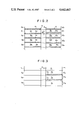
- FIG. 2 is a schematic view for illustrating the manner of determining the correction coefficient for each of the deflecting surfaces of the multifaceted mirror when the scan lines are intended to be arranged so that adjacent scan lines overlap each other, and
- FIG. 3 is a schematic view similar to FIG. 2 but when the scan lines are intended to arranged so that adjacent scan lines adjoin side by side with each other.
- FIG. 1 is a schematic view showing an example of a radiation image read-out apparatus adapted to be employed in the radiation image recording and reproducing system.
- a laser beam 1a having a predetermined intensity is emitted by a laser beam source 1 to impinge upon a multifaceted mirror 2 which is rotated at a predetermined speed by an electric motor 2a.
- the laser beam 1a is deflected by the multifaceted mirror 2 to form a scanning laser beam 1b which scans a stimulable phosphor sheet 3 in the main scanning direction or the direction of the width thereof as shown by the arrow A.
- the sheet 3 While the scanning laser beam 1b impinges upon the stimulable phosphor sheet 3, the sheet 3 is conveyed at a predetermined speed in a sub-scanning direction perpendicular to the main-scanning direction as indicated by the arrow B, for example, by an endless belt device 9, whereby the sheet 3 is two-dimensionally scanned with the scanning laser beam 1b.
- the portion of the sheet 3 exposed to the scanning laser beam 1b emits light having an intensity proportional to the radiation energy stored.
- the light emitted by the sheet 3 enters a transparent light guide member 4 from its front end face 4a positioned close to the sheet 3 in parallel to the main-scanning line.
- the light guide member 4 has a flat-shaped front end portion 4b positioned close to the sheet 3 and is shaped gradually into a cylindrical shape toward its rear end to form a substantially cylindrical rear end portion 4c which is closely contacted with a photomultiplier 5.
- the light emitted by the stimulable phosphor sheet 3 upon stimulation thereof and entering the light guide member 4 from its front end face 4a is guided inside of the light guide member 4 up to the rear end portion 4c, and received by the photomultiplier 5.
- the electric image signal thus obtained is sent to an image processing circuit 6 to be processed therein.
- the processed image signal may be reproduced into a visible image on a CRT 7 or may be stored in a magnetic recording tape 8. If desired, a hard copy can be obtained on a photographic light-sensitive material from the processed image signal.
- one scan line is drawn on the sheet 3 by each deflecting surface of the multifaceted mirror 2.
- the scan lines are intended to be positioned so that adjacent scan lines overlap each other by a predetermined width as shown in the left side part of FIG. 2 or adjoin side by side with each other as shown in the left side part of FIG. 3. That is, the left side parts of FIGS. 2 and 3 show arrangements of scan lines when the orientation of all the deflecting surfaces of the multifaceted mirror 2 is proper, respectively for the case that the scan lines are intended to be arranged to overlap each other and for the case that the scan lines are intended to be arranged to adjoin side by side with each other.
- the former case will be first described with reference to FIG. 2.
- the right side part of FIG. 2 shows an example of the arrangement of the scan lines when some of the deflecting surfaces of the multifaceted mirror 2 are improperly oriented.
- the scan lines are regularly formed as indicated at S0 to S4 with the center to center distances between adjacent scan lines being uniform and the overlapping portions a1 to a5 between adjacent scan lines being uniform in width. Accordingly, the "non-overlapping portions" b1 to b4 of the respective scan lines S0 to S4 are uniform in width.
- the electric image signal obtained from a certain scan line corresponds to the amount of light emitted by the part of the stimulable phosphor sheet 3 corresponding to the non-overlapping portion and the rear overlapping portion (the overlapping portion between the scan line and the next scan line).
- the image signal obtained from the scan line S2 corresponds to the amount of light emitted by the part of the stimulable phosphor sheet 3 corresponding to the non-overlapping portion b2 and the rear overlapping portion a3 since the radiation energy stored in the front overlapping portion a2 has been exhausted through scanning of the stimulating laser beam b1 along the preceding scan line S1.
- the amount of light emitted by the part of the stimulable phosphor sheet 3 along each scan line is proportional to the amount of radiation energy stored therein and to the total width or the total area of the non-overlapping portion, e.g., b2 and the rear overlapping portion, e.g., a3 provided that the power distribution of the stimulating laser beam 1b is uniform. Therefore, if the total width of the non-overlapping portion and the rear overlapping portion (determined by the width of the front overlapping portion, after all) fluctuates, the obtained electric image signal becomes incorrect.
- the scan lines drawn by the improperly oriented deflecting surfaces are shifted in the sub-scanning direction and the center to center distances between adjacent scan lines fluctuate, whereby the widths of the overlapping portions between adjacent scan lines fluctuate and sometimes a space is formed between adjacent scan lines as shown in the right side part of FIG. 2.
- the scan lines are indicated at S'0 to S'4 and the overlapping portions are indicated at a'1 to a'5 with the exception that a'3 denotes a space, or a portion which is not covered with the scan lines.
- the width of each scan line is equal to that of the scan lines shown in the left side part of FIG.
- the width of the front overlapping portion a'1 is equal to that of the regular scan line, e.g., the width of the overlapping portion a1, and accordingly the total width or area of the non-overlapping portion b'1 and the rear overlapping portion a'2 which is equal to the value obtained by subtracting the width of the front overlapping portion a'1 from the entire width of the scan line S'1, is equal to that of the regular scan line, e.g., the total width of the non-overlapping portion b1 and the rear overlapping portion a2.
- the correction coefficient k1 for the deflecting surface drawing the scan line S'1 is determined to be unity.
- the area obtained by subtracting the area of the front overlapping portion from the entire area of each scan line, i.e., the area of the scan line which actually contributes to emission of light by the sheet, will be referred to as "the effective area”, hereinafter.
- the scan line S'2 is shifted toward the scan line S'1 by distance d1, and accordingly the front overlapping portion a'2 is wider than the regular width by d1. Further, the scan line S'3 is shifted away from the scan line S'2, and the overlapping portion a'3 therebetween has negative width, that is, the scan lines S'2 and S'3 are spaced away from each other.
- the amount of light emitted by the stimulable phosphor sheet 3 upon scanning along the scan line S'2 becomes smaller than that of light emitted by the sheet 3 upon scanning along the scan line S'1 even if the amount of radiation energy stored in the parts of the sheet 3 corresponding to the scan lines S'1 and S'2 are equal.
- the electric image signal obtained from the scan line S'2 must be corrected taking into account the reduction in effective area of the scan line S'2.
- correction coefficient k2 for the deflecting surface drawing the scan line S'2 is selected as a value which produces the effective area of the regular scan line when multiplied by the effective area of the scan line S'2.
- the scan line S'3 is shifted away from the scan line S'2 and has no front overlapping portion. Therefore, the effective area of the scan line S'3 is the entire area thereof and larger than the effective area of the regular scan line. Accordingly, correction coefficient k3 for the deflecting surface drawing the scan line S'3 is selected so that the product of the correction coefficient and the entire area of the scan line S'3 is equal to the effective area of the regular scan line. Therefore, the value of the correction coefficient k3 is smaller than unity.
- image signal read-out errors due to incorrect orientation of the deflecting surfaces of the multifaceted mirror can be corrected by simply multiplying the electric image signal read out from each scan line by the correction coefficient which is thus determined and is specific to the deflecting surface drawing the scan line. All the electric image signals for the picture elements on one scan line are corrected by the same correction coefficient.
- each correction coefficient may be mathematically determined by measuring the inclining angle of each deflecting surface, or may be determined by reading out electric image signals upon scanning a stimulable phosphor sheet which has been uniformly exposed to a radiation and determining the correction coefficients so that the electric image signals read out from all the scan lines become equal to each other in level.
- the left side part of FIG. 3 shows the arrangement of scan lines when the scan lines are intended to be arranged to adjoin side by side with each other without space or overlapping portion therebetween and it is assumed that all the deflecting surfaces are properly oriented. That is, the scan lines T1, T2, T3, T4 . . . are regularly formed adjoining side by side with each other.
- the right side part of FIG. 3 shows an example of the arrangement of scan lines when some of the deflecting surfaces of the multifaceted mirror are improperly oriented. It is assumed that scan lines T'1, T'2, T'3 and T'4 in the right side part of FIG. 3 are drawn by first to fourth deflecting surfaces of the multifaceted mirror 2, respectively.
- the correction coefficient Fk for the k-th deflecting surface may be of a value which satisfies the following formula.
- the scan lines T'1 and T'2 adjoin side by side with each other without any overlapping portion or a space therebetween. Accordingly, the effective area of the scan line T'2 is the entire area thereof and is equal to the effective area of the regular scan line, e.g., T1. Therefore, the electric image signal R2 obtained from the scan line T'2 need not be corrected.
- the scan line T'3 overlaps with the scan line T'2 at its front part as indicated at c3. Therefore, the effective area of the scan line T'3 indicated at f3 is smaller than the effective area of the regular scan line by the area of the overlapping portion c3.
- the value of the signal C3 corresponding to the overlapping portion c3 is approximately calculated from the corrected value S2 of the signal obtained from the previous scan line T'2 and is added to the value R3 of the signal obtained from the effective area of the scan line T'3, thereby obtaining corrected value S3. That is,
- S3 R3+C3.
- the value of the c3/(f2+c3) is determined by the inclining angle of the third deflecting surface of the multifaceted mirror.
- F3 the following formula is satisfied.
- the scan line T'4 is spaced away from the previous scan line T'3, accordingly the image information stored in the part of the sheet 3 corresponding to the space c4 between the scan lines T'3 and T'4 is not read out.
- the image signal read-out error due to improper orientation of the deflecting surfaces of the multifaceted deflector can be corrected through calculation and no optical means is required for correction of such read-out errors. Therefore, the size and manufacturing cost of the system can be substantially reduced.
Landscapes
- Engineering & Computer Science (AREA)
- Multimedia (AREA)
- Signal Processing (AREA)
- Physics & Mathematics (AREA)
- Health & Medical Sciences (AREA)
- Life Sciences & Earth Sciences (AREA)
- General Physics & Mathematics (AREA)
- High Energy & Nuclear Physics (AREA)
- Molecular Biology (AREA)
- Spectroscopy & Molecular Physics (AREA)
- Facsimile Scanning Arrangements (AREA)
- Radiography Using Non-Light Waves (AREA)
- Mechanical Optical Scanning Systems (AREA)
Applications Claiming Priority (2)
| Application Number | Priority Date | Filing Date | Title |
|---|---|---|---|
| JP58-131566 | 1983-07-19 | ||
| JP58131566A JPS6023820A (ja) | 1983-07-19 | 1983-07-19 | 放射線画像情報読取誤差補正方法 |
Publications (1)
| Publication Number | Publication Date |
|---|---|
| US4642462A true US4642462A (en) | 1987-02-10 |
Family
ID=15061053
Family Applications (1)
| Application Number | Title | Priority Date | Filing Date |
|---|---|---|---|
| US06/631,844 Expired - Lifetime US4642462A (en) | 1983-07-19 | 1984-07-18 | Method of correcting radiation image read-out error |
Country Status (2)
| Country | Link |
|---|---|
| US (1) | US4642462A (de) |
| JP (1) | JPS6023820A (de) |
Cited By (3)
| Publication number | Priority date | Publication date | Assignee | Title |
|---|---|---|---|---|
| US4985629A (en) * | 1988-08-24 | 1991-01-15 | Fuji Photo Film Co., Ltd. | Shading elmination method for an image read-out apparatus |
| US5760416A (en) * | 1995-10-11 | 1998-06-02 | Konica Corporation | Radiographic image information reading apparatus |
| US20020060286A1 (en) * | 2000-11-22 | 2002-05-23 | Fuji Photo Film Co., Ltd. | Image processing apparatus |
Citations (5)
| Publication number | Priority date | Publication date | Assignee | Title |
|---|---|---|---|---|
| US4195316A (en) * | 1978-12-22 | 1980-03-25 | Pitney Bowes Inc. | Apparatus and method for correcting imperfection in a polygon used for laser scanning |
| US4258264A (en) * | 1978-07-12 | 1981-03-24 | Fuji Photo Film Co., Ltd. | Method of and apparatus for reading out a radiation image recorded in a stimulable phosphor |
| US4318582A (en) * | 1979-01-17 | 1982-03-09 | Canon Kabushiki Kaisha | Two-dimensional scanning apparatus |
| US4404596A (en) * | 1980-12-11 | 1983-09-13 | Dr. Ing. Rudolf Hell Gmbh | Method and apparatus for the correction of the position error of a multifaceted rotating mirror |
| US4484073A (en) * | 1980-10-30 | 1984-11-20 | Fuji Photo Film Co., Ltd. | Method of and apparatus for reading out radiation image information |
Family Cites Families (4)
| Publication number | Priority date | Publication date | Assignee | Title |
|---|---|---|---|---|
| US4046091A (en) * | 1976-10-12 | 1977-09-06 | Coast Catamaran Corporation | Method and apparatus for securing pylon and deck to the hull of a sailing vessel |
| JPS5611347A (en) * | 1979-07-11 | 1981-02-04 | Fuji Photo Film Co Ltd | Radiation picture information read gain set device |
| JPS5827466A (ja) * | 1981-08-11 | 1983-02-18 | Konishiroku Photo Ind Co Ltd | シエ−デイング補正装置 |
| JPH084297B2 (ja) * | 1983-06-09 | 1996-01-17 | 富士写真フイルム株式会社 | 放射線画像情報読取り誤差補正方法 |
-
1983
- 1983-07-19 JP JP58131566A patent/JPS6023820A/ja active Granted
-
1984
- 1984-07-18 US US06/631,844 patent/US4642462A/en not_active Expired - Lifetime
Patent Citations (5)
| Publication number | Priority date | Publication date | Assignee | Title |
|---|---|---|---|---|
| US4258264A (en) * | 1978-07-12 | 1981-03-24 | Fuji Photo Film Co., Ltd. | Method of and apparatus for reading out a radiation image recorded in a stimulable phosphor |
| US4195316A (en) * | 1978-12-22 | 1980-03-25 | Pitney Bowes Inc. | Apparatus and method for correcting imperfection in a polygon used for laser scanning |
| US4318582A (en) * | 1979-01-17 | 1982-03-09 | Canon Kabushiki Kaisha | Two-dimensional scanning apparatus |
| US4484073A (en) * | 1980-10-30 | 1984-11-20 | Fuji Photo Film Co., Ltd. | Method of and apparatus for reading out radiation image information |
| US4404596A (en) * | 1980-12-11 | 1983-09-13 | Dr. Ing. Rudolf Hell Gmbh | Method and apparatus for the correction of the position error of a multifaceted rotating mirror |
Cited By (4)
| Publication number | Priority date | Publication date | Assignee | Title |
|---|---|---|---|---|
| US4985629A (en) * | 1988-08-24 | 1991-01-15 | Fuji Photo Film Co., Ltd. | Shading elmination method for an image read-out apparatus |
| US5760416A (en) * | 1995-10-11 | 1998-06-02 | Konica Corporation | Radiographic image information reading apparatus |
| US20020060286A1 (en) * | 2000-11-22 | 2002-05-23 | Fuji Photo Film Co., Ltd. | Image processing apparatus |
| US6878928B2 (en) * | 2000-11-22 | 2005-04-12 | Fuji Photo Film Co., Ltd. | Image recording and read-out apparatus |
Also Published As
| Publication number | Publication date |
|---|---|
| JPS6023820A (ja) | 1985-02-06 |
| JPH0473567B2 (de) | 1992-11-24 |
Similar Documents
| Publication | Publication Date | Title |
|---|---|---|
| US4551626A (en) | Method of correcting radiation image read-out error | |
| US4616129A (en) | Light detecting apparatus | |
| JPH01131516A (ja) | 光ビーム走査装置 | |
| US4985629A (en) | Shading elmination method for an image read-out apparatus | |
| US5086228A (en) | Method for eliminating nonuniformity in sensitivity in image read-out apparatuses | |
| US4712009A (en) | Apparatus for scanning sheet-shaped recording medium | |
| US4749861A (en) | Method and apparatus for radiation image read-out | |
| US6495849B2 (en) | Radiation image read-out apparatus | |
| US4642462A (en) | Method of correcting radiation image read-out error | |
| US4755672A (en) | Radiation image reproducing method and apparatus | |
| US4816688A (en) | Radiation image read-out apparatus for stimulable phosphor sheet | |
| US5550385A (en) | Method and apparatus for detecting abnormal image patterns | |
| US5122659A (en) | Radiation image read-out apparatus having a beam number reducing device | |
| US5229618A (en) | Radiation image read-out apparatus compensating for image distortion | |
| JPS61189763A (ja) | 放射線画像情報読取方法 | |
| US5051588A (en) | Radiation image read-out apparatus | |
| US5337076A (en) | Method and apparatus for reproducing images including a multiple scanning operation | |
| US5266804A (en) | Shading elimination method for image read-out apparatuses | |
| JPH03198039A (ja) | 画像読取装置 | |
| US5352903A (en) | Radiation image read-out apparatus | |
| US5081356A (en) | Image read-out apparatus | |
| US4873440A (en) | Electron microscope image output method and apparatus | |
| US4629900A (en) | Radiation image read-out method | |
| JPH02237267A (ja) | 画像記録装置における濃度ムラ補正方法 | |
| US4916310A (en) | Image read-out apparatus with image signal adding |
Legal Events
| Date | Code | Title | Description |
|---|---|---|---|
| AS | Assignment |
Owner name: FUJI PHOTO FILM CO., LTD 210 NAKANUMA, MINAMIASHIG Free format text: ASSIGNMENT OF ASSIGNORS INTEREST.;ASSIGNORS:AAGANO, TOSHITAKA;TAKASAKI, YOSHIMI;REEL/FRAME:004290/0929 Effective date: 19840710 |
|
| STCF | Information on status: patent grant |
Free format text: PATENTED CASE |
|
| FEPP | Fee payment procedure |
Free format text: PAYOR NUMBER ASSIGNED (ORIGINAL EVENT CODE: ASPN); ENTITY STATUS OF PATENT OWNER: LARGE ENTITY |
|
| FPAY | Fee payment |
Year of fee payment: 4 |
|
| FPAY | Fee payment |
Year of fee payment: 8 |
|
| AS | Assignment |
Owner name: PROFUTURES BRIDGE CAPTIAL FUND, L.P., COLORADO Free format text: SECURITY AGREEMENT & INTER-CREDITOR AGREEMENT;ASSIGNOR:POSITRON CORPORATION;REEL/FRAME:008261/0246 Effective date: 19961114 |
|
| FPAY | Fee payment |
Year of fee payment: 12 |