US4654657A - Circuit arrangement containing wire matrix for signal transmission in elevator installations - Google Patents
Circuit arrangement containing wire matrix for signal transmission in elevator installations Download PDFInfo
- Publication number
- US4654657A US4654657A US06/516,585 US51658583A US4654657A US 4654657 A US4654657 A US 4654657A US 51658583 A US51658583 A US 51658583A US 4654657 A US4654657 A US 4654657A
- Authority
- US
- United States
- Prior art keywords
- conductors
- column
- circuit arrangement
- wire matrix
- opto
- Prior art date
- Legal status (The legal status is an assumption and is not a legal conclusion. Google has not performed a legal analysis and makes no representation as to the accuracy of the status listed.)
- Expired - Lifetime
Links
- 239000011159 matrix material Substances 0.000 title claims abstract description 49
- 230000008054 signal transmission Effects 0.000 title claims abstract description 20
- 238000009434 installation Methods 0.000 title claims description 19
- 239000004020 conductor Substances 0.000 claims abstract description 130
- 230000005693 optoelectronics Effects 0.000 claims abstract description 14
- 230000002457 bidirectional effect Effects 0.000 claims abstract description 7
- 230000005855 radiation Effects 0.000 claims abstract description 4
- 230000002093 peripheral effect Effects 0.000 claims description 38
- 210000000352 storage cell Anatomy 0.000 claims description 12
- 230000004913 activation Effects 0.000 claims description 3
- 125000004122 cyclic group Chemical group 0.000 claims description 3
- 238000001514 detection method Methods 0.000 claims 1
- 230000000007 visual effect Effects 0.000 claims 1
- 230000011664 signaling Effects 0.000 abstract description 11
- 230000005540 biological transmission Effects 0.000 abstract description 6
- 230000009977 dual effect Effects 0.000 abstract description 2
- 108010066114 cabin-2 Proteins 0.000 description 13
- 230000000903 blocking effect Effects 0.000 description 5
- 239000000725 suspension Substances 0.000 description 5
- 230000003213 activating effect Effects 0.000 description 3
- 238000010586 diagram Methods 0.000 description 3
- 238000010276 construction Methods 0.000 description 1
- 230000000694 effects Effects 0.000 description 1
- 230000005284 excitation Effects 0.000 description 1
- 230000007257 malfunction Effects 0.000 description 1
- 230000003287 optical effect Effects 0.000 description 1
- 238000005070 sampling Methods 0.000 description 1
Images

Classifications
-
- B—PERFORMING OPERATIONS; TRANSPORTING
- B66—HOISTING; LIFTING; HAULING
- B66B—ELEVATORS; ESCALATORS OR MOVING WALKWAYS
- B66B1/00—Control systems of elevators in general
- B66B1/34—Details, e.g. call counting devices, data transmission from car to control system, devices giving information to the control system
- B66B1/3415—Control system configuration and the data transmission or communication within the control system
-
- B—PERFORMING OPERATIONS; TRANSPORTING
- B66—HOISTING; LIFTING; HAULING
- B66B—ELEVATORS; ESCALATORS OR MOVING WALKWAYS
- B66B1/00—Control systems of elevators in general
- B66B1/34—Details, e.g. call counting devices, data transmission from car to control system, devices giving information to the control system
-
- B—PERFORMING OPERATIONS; TRANSPORTING
- B66—HOISTING; LIFTING; HAULING
- B66B—ELEVATORS; ESCALATORS OR MOVING WALKWAYS
- B66B1/00—Control systems of elevators in general
- B66B1/34—Details, e.g. call counting devices, data transmission from car to control system, devices giving information to the control system
- B66B1/3415—Control system configuration and the data transmission or communication within the control system
- B66B1/3446—Data transmission or communication within the control system
-
- B—PERFORMING OPERATIONS; TRANSPORTING
- B66—HOISTING; LIFTING; HAULING
- B66B—ELEVATORS; ESCALATORS OR MOVING WALKWAYS
- B66B1/00—Control systems of elevators in general
- B66B1/34—Details, e.g. call counting devices, data transmission from car to control system, devices giving information to the control system
- B66B1/46—Adaptations of switches or switchgear
- B66B1/468—Call registering systems
Definitions
- the present invention relates to a new and improved circuit arrangement containing a wire matrix for signal transmission in elevator installations or the like.
- the invention relates to a new and improved circuit arrangement containing a wire matrix for signal transmission in elevator installations in which a matrix-shaped arrangement of conductors or lines can be controlled by means of line and column driving circuits or drivers via opto-couplers connected to a control unit, whereby peripheral signal transmitters and peripheral signal receivers can be connected to a central signal processing system or station.
- elevator installations such arrangements serve as a transmitter apparatus for the acquisition of data by means of the elevator control serving, for example, for cabin and storey calls as well as call acknowledgement or receipting and signalling in the elevator cabin and at the storeys of the building.
- the invention is based on the recognition that by using a matrix-shaped conductor or line arrangement the electronic and installational expense for connecting signal sources and signal receiving locations can be strongly reduced.
- a matrix-shaped conductor or line arrangement the electronic and installational expense for connecting signal sources and signal receiving locations can be strongly reduced.
- the electronic and installational expense for connecting signal sources and signal receiving locations can be strongly reduced.
- an 8 by 8-matrix including just sixteen driving channels for each of the eight column and line conductors sixty-four intersection or crossing points can be selectively controlled.
- matrix-shaped, partially mutually orthogonally aligned conductor or line arrangements can achieve cost savings with respect to electronics and connecting lines. It was therefore obvious, particularly in elevator installations in which the expense for the electronics, the installation and the required space are substantially determined by the logic inputs as well as by the signalling system, to utilize the matrix concept.
- Matrix-shaped conductor arrangements as known, for example, from German Patent Publication No. 2,422,246 and its cognate U.S. Pat. No. 3,898,611, granted Aug. 5, 1975 and German Pat. No. 2,422,248 and its cognate U.S. Pat. No. 3,882,447, granted May 6, 1975, serve in elevator installations to activate the position indicators in elevator cabins as well as the signalling lamps positioned at the storeys.
- the indicator or display lamps for the individual storeys are arranged at the intersection or crossing points of a matrix, the lines and columns of which are each connected to a driving circuit or driver to which there is selectively applied the corresponding position or indicator signal.
- a distinct group of storeys of a building is associated with each line conductor and a distinct storey in a group is associated with each column conductor.
- Another and more specific object of the present invention is directed to the provision of a new and improved circuit arrangement containing a wire matrix for signal transmission in elevator installations which enables connecting peripheral signal transmitters and peripheral signal receivers to a central signal processing system.
- Still a further significant object of the present invention aims at providing a new and improved circuit arrangement containing a wire matrix for signal transmission in elevator installations in which peripheral signal transmitters and peripheral signal receivers are connected to a central signal processing system and in which the expense required therefor in terms of electronical and installational measures, is markedly and decisively reduced as compared with heretofore known circuit arrangements.
- Another noteworthy object of the present invention is directed to a new and improved circuit arrangement containing a wire matrix for signal transmission in elevator installations or the like which is fully compatible with standardized circuits as used in modern information or data systems.
- a bidirectional signal transmission by means of a wire matrix comprising a first group of column conductors for transmitting a signal from the periphery to a central signal processing system or station, a second group of column conductors for transmitting signals in the reverse direction as well as line conductors common to all column conductors.
- Peripheral signal transmitters are connected to first crossing points or intersections of the line conductors with the first group of column conductors and, peripheral signal receivers are connected to second crossing points or intersections of the line conductors with the second group of column conductors.
- the signal transmitters and signal receivers can be connected by cyclically scanning the line conductors by means of a control unit which forms a component or part of a microprocessor, linewise and in a time-division multiplex operation via the column conductors to an information or data concentrator which also forms a component or part of the microprocessor.
- a first advantage achieved by the invention is based upon the functionally two-fold or dual utilization of the wire matrix. Since line conductors are used which are common to both functions of detecting the peripheral signal transmitter and activating the peripheral signal receiver, one group of line conductors can be saved in comparison to conventional arrangements having the same function. Thus, also the activating electronic installations required therefore and the connecting lines thereof leading to the command unit and to the signal processing system can be saved. The expense, which is already reduced due to the use of only one matrix arrangement, is thus additionally reduced by the functional two-fold utilization of the line conductors.
- FIG. 1 is a block diagram schematically illustrating an elevator installation or system equipped with the inventive circuit arrangement for bidirectional signal transmission;
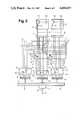
- FIG. 2 is a detailed circuit diagram of the circuit arrangement according to the invention as shown in FIG. 1.
- FIG. 1 there has been schematically illustrated therein an elevator installation, of which a lift or elevator shaft is only partially illustrated and has been generally designated by reference character 1.
- An elevator or lift cabin 2 is movably guided in the elevator shaft 1.
- a standard conveying or drive machine 3 which is controlled by a suitable drive control (not shown) drives the elevator cabin 2 via a conveying cable or rope 4.
- the elevator system services thirty-two storeys St 1 to St 32 .
- Elevator shaft doors arranged at the different storeys of the building have been designated by reference characters T 1 to T 32 .
- a circuit arrangement 6 constructed according to the invention and serving for the bidirectional signal transmission between peripheral signalling devices 12, 13 in the elevator cabin 2 or at the storeys St 1 to St 32 and a central signal processing system 5 in the elevator control 7 is placed in the elevator cabin 2 and at a central storey like, for example, the building storey St 16 .
- Both connection systems are analogously constructed. Therefore in the following description only the connection system from the elevator cabin 2 to the elevator control 7 will be explained in detail, wherein the signalling devices 12, 13 present in the elevator cabin 2 can be connected to the central signal processing system or station 5 via a twin-wire line or cable 38 which is present in the suspension cable 11.
- a wire matrix 8 which is controlled via an interface 9 by a microprocessor 10 which also belongs to the signal transmission apparatus.
- the wire matrix 8 will be explained in greater detail with reference to FIG. 2 in the description to follow hereinafter.
- Peripheral signal transmitters 12 and peripheral signal receivers 13 are each connected via a twin-wire conductor or line 31, in the direction of the periphery of the arrangement, to the wire matrix 8 for the inputting and reception, respectively, on the side of the elevator cabin 2 of signals transmitted between the elevator cabin 2 and the central signal processing system 5.
- signal transmitters 12 there are provided, for instance, push-button switches 12.1 for cabin calls as well as limit or terminal switches 12.2 for the door drive and the elevator cabin floor load.
- the peripheral signal transmitters 12 equally may be constituted by relay contacts, sensors and so forth.
- the signal receivers 13 are designed as opto-electronic indicator or display elements 13.1 for signalling purposes or as electro-acoustic signalling devices, such as gongs or chimes 13.2.
- the wire matrix 8 is connected in the direction of the central signal processing system 5 via the interface 9 to the microprocessor 10 and via a serial interface 14 and the twin-wire conductor or line 38 in the suspension cable 11 to the central signal processing system 5.
- FIG. 2 which is partially illustrated as a circuit diagram or scheme, the circuit arrangement 6 of FIG. 1 is shown in a more detailed representation.
- the wire matrix 8 contains a first group of eight column conductors or lines S 0 to S 7 for the transmission of signals from the peripheral signal transmitters 12 to the microprocessor 10, a second group of eight column conductors or lines S 8 to S 15 for transmitting signals in the reverse direction from the microprocessor 10 to the signal receivers 13 and eight line conductors or lines Z 0 to Z 7 for providing the connection scheme via the first and second group of column conductors S 0 to S 7 and S 8 to S 15 .
- the line conductors Z 0 to Z 7 are associated with both groups of column conductors S 0 to S 7 and S 8 to S 15 , and thus, are also common to both signal transmission directions. They are thus utilized in a two-fold functional manner.
- the wire matrix 8 is illustrated in the form of orthogonally crossing or intersecting line conductors Z and column conductors S 0 to S 15 .
- a respective line conductor driving circuit or drive 16 is operatively associated with each one of the line conductors Z 0 to Z 7 , while each of the groups of column conductors S 0 to S 7 and S 8 to S 15 comprises a respective column conductor driving circuit or driver 17 and 18, respectively.
- the sign "+” appearing at the top of the collector of the uppermost transistor 28 depicted in the column driver 18 and the symbol “ ⁇ " appearing at the end of the emitter of the uppermost transistor 19 depicted in the line driver 16 represent potentials and terminals of not further illustrated voltage sources.
- the line conductor driving circuit 16 contains, for each line conductor Z, a transistor 19 which is connected to act as an active-0-driver with respect to the null or zero-signals.
- the collector and the emitter of the transistor 19 are connected in known manner to the respectively associated line conductor Z and ground.
- the base of the transistor 19 is connected to an opto-coupler 20 which provides the connection to the microprocessor 10 and which comprises, for instance, an infrared emitting or luminescent diode 20.1 and a phototransistor 20.2.
- each column conductor in the first group of column conductors S 0 to S 7 is electrically connected, with respect to signals, via a respective opto-coupler 21 composed of an infrared emitting or luminescent diode 21.1 connected to a positive terminal pole and a phototransistor 21.2 to a first group of storage cells 25 which are combined to form a first buffer.
- a respective opto-coupler 21 composed of an infrared emitting or luminescent diode 21.1 connected to a positive terminal pole and a phototransistor 21.2 to a first group of storage cells 25 which are combined to form a first buffer.
- the second column conductor driving circuit 18 contains, for each one of the column conductors in the second group of column conductors S 8 to S 15 , a transistor 28 which is connected to act as an active-1-driver for one-signals and the collector and emitter of which are connected to a positive terminal or pole and to a related column conductor.
- the opto-couplers 22 in the second column conductor driving circuit 18 are designed in the same way as the opto-couplers 20 in the line conductor driving circuit 16.
- the opto-couplers 22 lead the outputs of second storage cells 29 to the inputs of the related transistors 28.
- Each of the peripheral signal transmitters 12 is connected via a twin-wire conductor 31 and a blocking diode 32 to a related first crossing point or intersection 36 formed by the corresponding line conductors Z 0 to Z 7 and the first group of column conductors S 0 to S 7 , while the peripheral signal receivers 13 are connected in analogous manner with second crossing points or intersections 37 formed by the corresponding line conductors Z 0 to Z 7 and the second group of column conductors S 8 to S 15 .
- blocking diodes 32 are required to prevent feedback and malfunctions of other devices caused thereby.
- the blocking diodes 32 are poled in such a manner that current may flow from the column conductors via the signal transmitters 12 or, respectively via the signal receivers 13 to the line conductors Z 0 to Z 7 .
- peripheral signal transmitters 12 In the elevator cabin 2 there are connected push-button switches 12.1 for passenger call input as well as limit or terminal switches 12.2 for the door drive and the cabin load so as to form peripheral signal transmitters 12.
- push-button switches 12.1 for passenger call input As well as limit or terminal switches 12.2 for the door drive and the cabin load so as to form peripheral signal transmitters 12.
- the peripheral signal receivers 13 in the elevator cabin 2 comprise predominantly opto-electronic indicator or display elements 13.1 for position indication and call acknowledgement or receipting of passenger storey calls. Also in this respect a maximum of sixty-four peripheral signal receivers 13 can be activated at the second crossing points or intersections 37 in the provided 8 by 8-matrix.
- the line conductors Z 0 to Z 7 and the column conductors S 0 to S 15 are connected via the interface 9 to a control unit 34 for controlling the wire matrix 8 and to an information or data concentrator 35 provided for the signals.
- the control unit 34 as well as the information or data concentrator 35 are designed to form components or sections of the microprocessor 10 which is arranged in the elevator cabin 2 and which is connected in known manner to the elevator control 7 for bidirectional signal transmission via the serial interface 14 and the suspension cable 11.
- the control unit 34 sequentially and in a pulsed operation grounds or earths the collectors of the transistors 19 which are connected to act as active-0-drivers for the logic or null zero-signal at a scanning ratio T 1 and at a scanning frequency f 1 .
- a current will flow during scanning of the line conductors Z 2 and Z 4 from the column conductors S 2 and S 4 via the blocking diodes 32, the push-button switch 12.1 and the limit switch 12.2, respectively, to the line conductors Z 2 and Z 4 , respectively, and from there to ground.
- the two currents are read into the corresponding first storage cells 25 via the related opto-couplers 21.
- the currents are transmitted as signals from the microprocessor 10 via the serial interface 14 and the twin-wire conductor 38 in the suspension cable 11 to the central signal processing system 5 in the elevator control 7.
- the scanning or sampling frequency f 1 for this operation is selected such that the shortest period of contact to be expected at the call transmitters and which amounts to about 20 milliseconds is still reliably detected. Contact periods of longer duration are therefore multiply scanned, and thus, also detected with increased reliability. It will be self-evident that not only two, but all sixty-four of the signal transmitters in the 8 by 8-matrix will be detected even when the signal transmission therefrom occurs at the same time.
- the column conductor S 15 is connected to the positive terminal or pole via the transistor 28 which is connected to act as an active-1-driver for the one-signal for the scanning period of the line conductor Z 4 . Consequently, current will flow from the column conductor S 15 via the blocking diode 32 and the opto-electronic indicator element 13.1, which may, for example,, be designed as a light-emitting diode, to the line conductor Z 4 and further to ground.
- the signal for activating the transistor 28 originates from the central signal processing system 5 from where it has been read into the associated second storage cell 29 via the suspension cable 11, the serial interface 14 and the microprocessor 10 to modulate or control the transistor 28 which is connected to act as an active-1-driver for one-signals via the opto-coupler 22.
- peripheral signalling devices 12, 13 are line-wise activated in a fixed-cycle or clock operation from the wire matrix 8, a pulse-shaped excitation current will result at the crossing point or intersection Z 4 , S 15 for the opto-electronic indicator element 13.1.
- the scanning frequency f 1 as well as the scanning ratio T 1 in the cyclic scanning operation are therefore selected such that a continuously emitted radiation of sufficient intensity will be visually discernible.
- S 15 it also will be possible to operate all of the crossing points or intersections 37 in the 8 by 8-matrix in this manner.
- the sixty-four opto-electronic indicator elements 13.1 will then simultaneously emit continuous radiation or light.
- the wire matrix 8 also may be selectively equipped with a different number of line conductors and column conductors. Consequently, it will be possible to optimumly adapt the inventive circuit arrangement to the requirements of a specific elevator installation or system and to provide as many transmission channels in the two transmission directions as actually required.
Landscapes
- Engineering & Computer Science (AREA)
- Automation & Control Theory (AREA)
- Computer Networks & Wireless Communication (AREA)
- Elevator Control (AREA)
- Indicating And Signalling Devices For Elevators (AREA)
- Selective Calling Equipment (AREA)
- Adornments (AREA)
- Table Equipment (AREA)
- Luminescent Compositions (AREA)
- Measurement Of Velocity Or Position Using Acoustic Or Ultrasonic Waves (AREA)
- Measuring Pulse, Heart Rate, Blood Pressure Or Blood Flow (AREA)
- Arrangements For Transmission Of Measured Signals (AREA)
Applications Claiming Priority (2)
| Application Number | Priority Date | Filing Date | Title |
|---|---|---|---|
| CH4932/82 | 1982-08-18 | ||
| CH4932/82A CH656598A5 (de) | 1982-08-18 | 1982-08-18 | Schaltungseinrichtung mit leitungsmatrix zur signaluebertragung in aufzugsanlagen. |
Publications (1)
| Publication Number | Publication Date |
|---|---|
| US4654657A true US4654657A (en) | 1987-03-31 |
Family
ID=4285042
Family Applications (1)
| Application Number | Title | Priority Date | Filing Date |
|---|---|---|---|
| US06/516,585 Expired - Lifetime US4654657A (en) | 1982-08-18 | 1983-07-25 | Circuit arrangement containing wire matrix for signal transmission in elevator installations |
Country Status (7)
| Country | Link |
|---|---|
| US (1) | US4654657A (de) |
| EP (1) | EP0100866B1 (de) |
| AT (1) | ATE19768T1 (de) |
| CA (1) | CA1197329A (de) |
| CH (1) | CH656598A5 (de) |
| DE (1) | DE3363506D1 (de) |
| FI (1) | FI73947C (de) |
Cited By (1)
| Publication number | Priority date | Publication date | Assignee | Title |
|---|---|---|---|---|
| US5726399A (en) * | 1996-02-06 | 1998-03-10 | Inventio Ag | Apparatus for scanning elevator call buttons |
Families Citing this family (3)
| Publication number | Priority date | Publication date | Assignee | Title |
|---|---|---|---|---|
| ATE35667T1 (de) * | 1985-01-12 | 1988-07-15 | Thyssen Man Aufzuege | Installationssystem fuer eine aufzugsanlage. |
| JP2007290868A (ja) | 2006-04-20 | 2007-11-08 | Inventio Ag | エレベータ設備の複数の操作ユニットの階関連付けを設定する方法 |
| EP1847499B1 (de) * | 2006-04-20 | 2015-06-10 | Inventio AG | Verfahren zur Einstellung der Stockwerkszuordnungen einer Vielzahl von Bedieneinheiten einer Aufzugsanlage |
Citations (9)
| Publication number | Priority date | Publication date | Assignee | Title |
|---|---|---|---|---|
| DE2422248A1 (de) * | 1973-05-08 | 1974-11-21 | Westinghouse Electric Corp | Anzeigevorrichtung fuer das eintreffen eines aufzugs in den einzelnen stockwerken eines gebaeudes |
| US3898611A (en) * | 1973-05-08 | 1975-08-05 | Westinghouse Electric Corp | Elevator system having a car position indicator which includes a matrix |
| US3974478A (en) * | 1973-08-09 | 1976-08-10 | Nippon Gakki Seizo Kabushiki Kaisha | Key switch scanning and encoding system |
| US4060795A (en) * | 1973-02-23 | 1977-11-29 | Hitachi, Ltd. | Scanning system |
| US4106593A (en) * | 1977-03-17 | 1978-08-15 | Westinghouse Electric Corp. | Methods and tools for servicing an elevator system |
| US4111284A (en) * | 1974-09-04 | 1978-09-05 | Westinghouse Electric Corp. | Elevator system |
| US4121197A (en) * | 1977-03-04 | 1978-10-17 | Nippon Electric Co., Ltd. | Matrix circuit for an electrostatic recording device comprising cross-point elements for driving each pair of control electrodes on a common matrix conductor |
| US4190836A (en) * | 1976-11-15 | 1980-02-26 | Hitachi, Ltd. | Dynamic drive circuit for light-emitting diodes |
| US4231016A (en) * | 1977-12-02 | 1980-10-28 | Matsushita Electric Industrial Co., Ltd. | Input signal recognition circuit |
Family Cites Families (3)
| Publication number | Priority date | Publication date | Assignee | Title |
|---|---|---|---|---|
| US3967700A (en) * | 1974-08-05 | 1976-07-06 | Armor Elevator Company, Inc. | Signaling system |
| US4019607A (en) * | 1975-05-16 | 1977-04-26 | Westinghouse Electric Corporation | Signal input devices and systems |
| CH622226A5 (de) * | 1977-07-29 | 1981-03-31 | Inventio Ag |
-
1982
- 1982-08-18 CH CH4932/82A patent/CH656598A5/de not_active IP Right Cessation
-
1983
- 1983-07-06 DE DE8383106592T patent/DE3363506D1/de not_active Expired
- 1983-07-06 AT AT83106592T patent/ATE19768T1/de not_active IP Right Cessation
- 1983-07-06 EP EP83106592A patent/EP0100866B1/de not_active Expired
- 1983-07-15 FI FI832583A patent/FI73947C/fi not_active IP Right Cessation
- 1983-07-21 CA CA000432895A patent/CA1197329A/en not_active Expired
- 1983-07-25 US US06/516,585 patent/US4654657A/en not_active Expired - Lifetime
Patent Citations (10)
| Publication number | Priority date | Publication date | Assignee | Title |
|---|---|---|---|---|
| US4060795A (en) * | 1973-02-23 | 1977-11-29 | Hitachi, Ltd. | Scanning system |
| DE2422248A1 (de) * | 1973-05-08 | 1974-11-21 | Westinghouse Electric Corp | Anzeigevorrichtung fuer das eintreffen eines aufzugs in den einzelnen stockwerken eines gebaeudes |
| US3882447A (en) * | 1973-05-08 | 1975-05-06 | Westinghouse Electric Corp | Hall lantern apparatus for elevator system |
| US3898611A (en) * | 1973-05-08 | 1975-08-05 | Westinghouse Electric Corp | Elevator system having a car position indicator which includes a matrix |
| US3974478A (en) * | 1973-08-09 | 1976-08-10 | Nippon Gakki Seizo Kabushiki Kaisha | Key switch scanning and encoding system |
| US4111284A (en) * | 1974-09-04 | 1978-09-05 | Westinghouse Electric Corp. | Elevator system |
| US4190836A (en) * | 1976-11-15 | 1980-02-26 | Hitachi, Ltd. | Dynamic drive circuit for light-emitting diodes |
| US4121197A (en) * | 1977-03-04 | 1978-10-17 | Nippon Electric Co., Ltd. | Matrix circuit for an electrostatic recording device comprising cross-point elements for driving each pair of control electrodes on a common matrix conductor |
| US4106593A (en) * | 1977-03-17 | 1978-08-15 | Westinghouse Electric Corp. | Methods and tools for servicing an elevator system |
| US4231016A (en) * | 1977-12-02 | 1980-10-28 | Matsushita Electric Industrial Co., Ltd. | Input signal recognition circuit |
Cited By (1)
| Publication number | Priority date | Publication date | Assignee | Title |
|---|---|---|---|---|
| US5726399A (en) * | 1996-02-06 | 1998-03-10 | Inventio Ag | Apparatus for scanning elevator call buttons |
Also Published As
| Publication number | Publication date |
|---|---|
| CH656598A5 (de) | 1986-07-15 |
| FI73947B (fi) | 1987-08-31 |
| FI832583A0 (fi) | 1983-07-15 |
| FI832583A7 (fi) | 1984-02-19 |
| CA1197329A (en) | 1985-11-26 |
| ATE19768T1 (de) | 1986-05-15 |
| EP0100866B1 (de) | 1986-05-14 |
| DE3363506D1 (en) | 1986-06-19 |
| FI73947C (fi) | 1987-12-10 |
| EP0100866A1 (de) | 1984-02-22 |
Similar Documents
| Publication | Publication Date | Title |
|---|---|---|
| AU614442B2 (en) | Remote supervisory and controlling system | |
| US4085403A (en) | Combined on-board remote control energy supply distribution and signaling system, particularly for automotive vehicles | |
| US4618932A (en) | Control device for at least two circulating shelving systems | |
| KR890003614A (ko) | 엘리베이터의 신호전송 방법 및 그의 장치 | |
| US3892372A (en) | Pneumatic carrier system with station control | |
| US5307058A (en) | Remote supervisory and controlling system | |
| US4013993A (en) | Elevator system | |
| US4655324A (en) | Method for privately controlling an elevator | |
| US4022296A (en) | Signal input devices and systems | |
| US4042067A (en) | Elevator system | |
| CA1197329A (en) | Circuit arrangement containing wire matrix for signal transmission in elevator installations | |
| US4191277A (en) | Apparatus for transmitting control signals to elevators or the like | |
| US4019607A (en) | Signal input devices and systems | |
| US5975248A (en) | Communications system | |
| US4803411A (en) | Industrial sewing machine | |
| GB2302602A (en) | Elevator monitoring apparatus | |
| US5502513A (en) | Three wire television remote control operable with key closures or data pulses | |
| US3882447A (en) | Hall lantern apparatus for elevator system | |
| KR860001441B1 (ko) | 엘리베이터의 호출신호 변환장치 | |
| JPH06206673A (ja) | 視覚障害者が使用するためのエレベータカー位置指示器 | |
| JPH0567554B2 (de) | ||
| US4788541A (en) | Signal communication system | |
| KR890001005B1 (ko) | 승강기용 인터폰 호출신호검출 및 호출호기신호 엔코드장치 | |
| CN86203494U (zh) | 电脑型电梯控制装置 | |
| KR100246659B1 (ko) | 승강기의 정차층 표시 및 이에 따른 승강기 운행 제어 장치 및 방법 |
Legal Events
| Date | Code | Title | Description |
|---|---|---|---|
| AS | Assignment |
Owner name: INVENTIO AG., 6052 HERGISWIL, SWITZERLAND A CORP. Free format text: ASSIGNMENT OF ASSIGNORS INTEREST.;ASSIGNOR:MEYER, FRITZ;REEL/FRAME:004157/0872 Effective date: 19830719 Owner name: INVENTIO AG., SWITZERLAND Free format text: ASSIGNMENT OF ASSIGNORS INTEREST;ASSIGNOR:MEYER, FRITZ;REEL/FRAME:004157/0872 Effective date: 19830719 |
|
| STCF | Information on status: patent grant |
Free format text: PATENTED CASE |
|
| FEPP | Fee payment procedure |
Free format text: PAYOR NUMBER ASSIGNED (ORIGINAL EVENT CODE: ASPN); ENTITY STATUS OF PATENT OWNER: LARGE ENTITY |
|
| FPAY | Fee payment |
Year of fee payment: 4 |
|
| FEPP | Fee payment procedure |
Free format text: PAYER NUMBER DE-ASSIGNED (ORIGINAL EVENT CODE: RMPN); ENTITY STATUS OF PATENT OWNER: LARGE ENTITY |
|
| FPAY | Fee payment |
Year of fee payment: 8 |
|
| FEPP | Fee payment procedure |
Free format text: PAYOR NUMBER ASSIGNED (ORIGINAL EVENT CODE: ASPN); ENTITY STATUS OF PATENT OWNER: LARGE ENTITY |
|
| FPAY | Fee payment |
Year of fee payment: 12 |